

Page 1
An OMEGA Techno lo g ie s Com pa ny
30/98
BS Series Model : 1
BCD parallel to serie RS-232 or RS-422
Interface coversion of 6 digits plus
minus polarity
SPECIFICATIONS
INPUTS
Date, Holds and decimal points
(positive logic) . . . . . . . Level logic 1 : >4.3 Vdc.
max. : 40 Vdc.
Level logic 0 : <1.1 Vdc.
Consumption. . . . . . . . . 4 mA at 24 Vdc.
(per channel) 1.5 mA at 12 Vdc.
150 µA at 5 Vdc.
CONTROLS
Hold. . . . . . . . One control pin for every digit and polarity.
Test. . . . . . . . One control pin for all digits. (LT).
Blanking . . . . One control pin for all digits. (BI).
OUTPUTS
Interface . . . . . . . . . . . . . . RS-232 / RS-422 internal.
jumper selectable.
Transmission rate . . . . . . 1200 Bauds.
Protocol . . . . . . . . . . . . . . STX, ETX.
Date . . . . . . . . . . . . . . . . . ASCII, 8 bit no parity.
ELECTRICAL
Standard power supply . . 230 Vac. ±10% 50/60 Hz.
Consumption. . . . . . . . . . . 2.8 VA max.
DATE OUTPUT.- Serie format, type RS-232 or RS-422, selectable
by internal jumper. Transmission rate is 1200 Bauds.
INPUT.- The input accepts six digits in BCD parallel code (1, 2,
4, 8) minus sign and six decimal points.
HOLD.- One pin is available to achieve function HOLD, in each
one of the digits, plus other pin for sign. This function allows the
user to multiplex the data inputs. If this function is not activated,
the interface unit transmits in a continuous way the BCD codes
which are presents in data input.
The logic level by default is 0 and this function is activated when
a logic level 1 is reached.
TEST (LT).- This function is activated when pin LT is linked to
level logic 0 (GND). Numerical characters sent are -8.8.8.8.8.8.
BLANKING (BI).- This function is activated when pin BI is
connected to level logic 0 (GND), in the output appears a string
of blank characters. If the output is connected to a display it will
switch off.
DECIMAL POINTS.- Until six decimal points can be controlled by
the data inputs or by the wiring in the input connectors.
MULTIPLEX.- A multiplexed system can be achieved, using only
one BCD parallel code, connecting all the parallel inputs and
operating with function HOLD, to select the digit corresponding
to the one sent it, by the BCD parallel code.
POLARITY.- With logic level 0, the sign is activated and it is
switched off when a logic level 1 is applied.
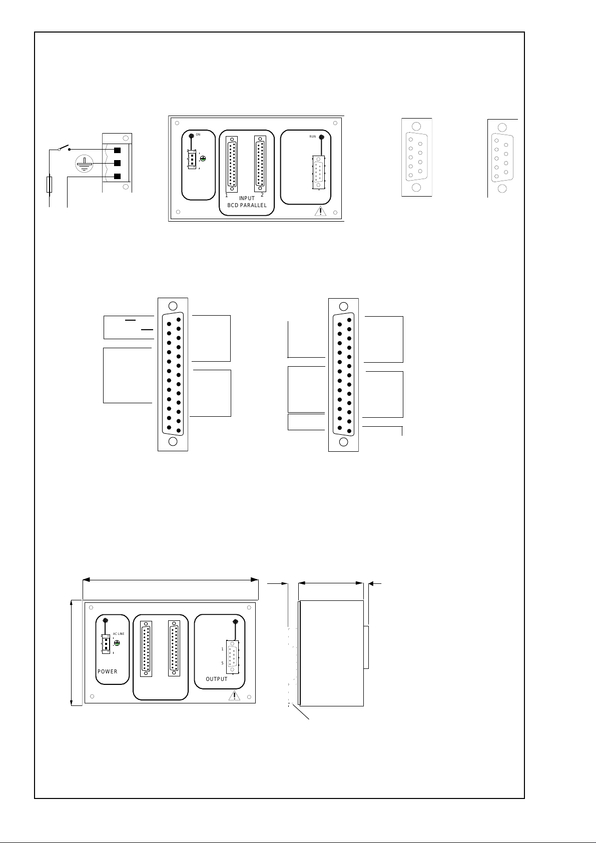
CONNECTORS.- Two 25 pins Sub-D male connectors, for BCD
data inputs.
One 9 pins Sub-D female connector, for the Serial data outputs.
One push-in cable connector, for Power Supply.
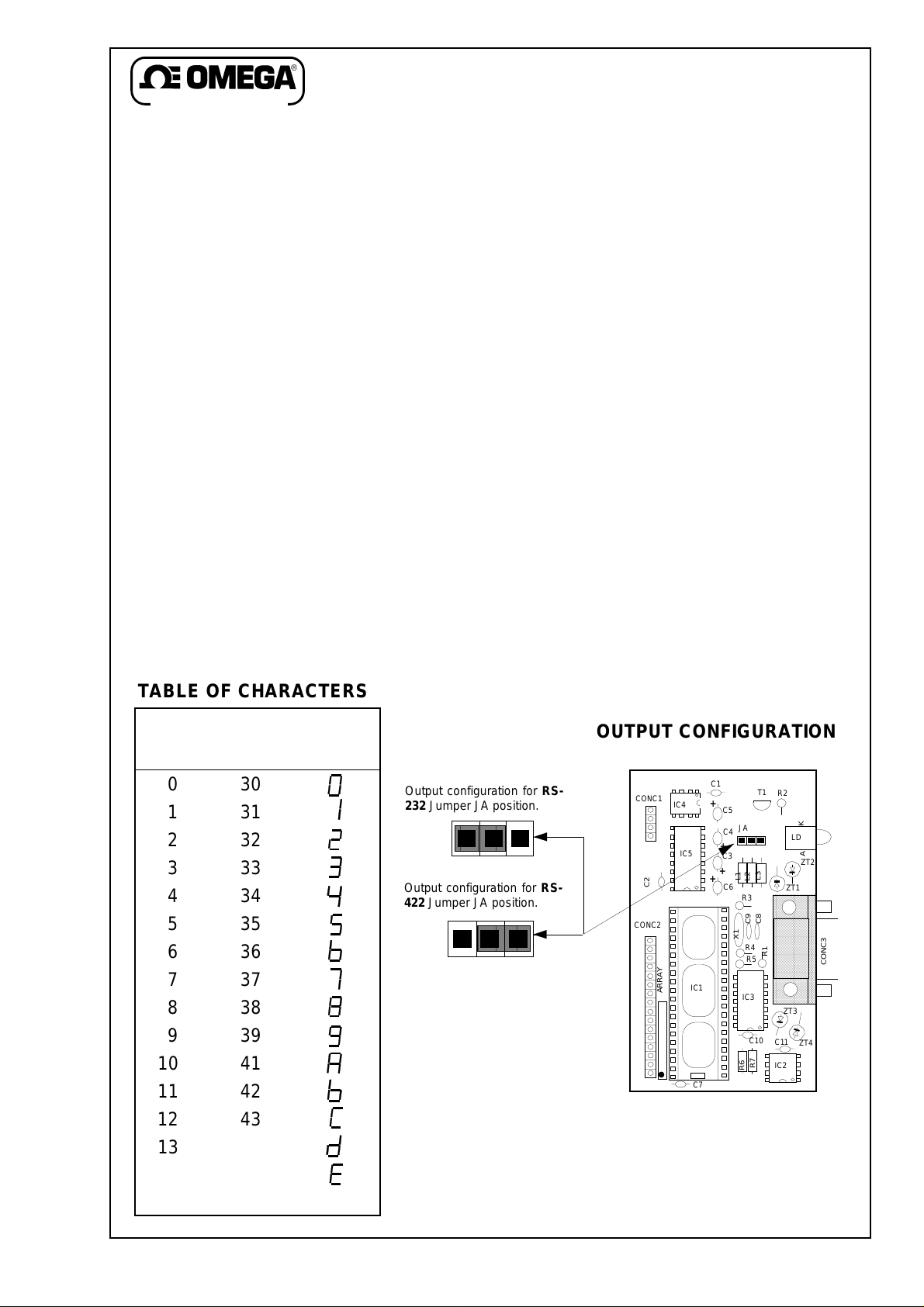
TABLE OF CHARACTERS
BCD ASCII Character
Code Hex Code
030
131
232
333
434
535
636
737
838
939
10 41
11 42
12 43
13 44
14 45
15 40 Blanking
Output configuration for RS-
232 Jumper JA position.
Output configuration for RS-
422 Jumper JA position.
1.- Remove the 4 screws on the frontal face.
2.- Remove the frontal face.
3.- Place the jumper JA on the position corresponding
to the desired type of output.
4.- Install the frontal face using the 4 screws removed
before.
OUTPUT CONFIGURATION
CONC1
CONC2
C1
+
IC4
IC5
C2
ARRAY
+
IC1
C7
T1
R2
C5
JA
C4
+
C3
+
L1
L2
C6
R3
C9
X1
R4
R5
K
LD
A
ZT2
L3
ZT1
C8
R1
IC3
ZT3
C10
C11
ZT4
IC2
R7
R6
CONC3
Output connector
Page 2
WIRING
OUTPUT CONFIGURATED
AS :
Recommended power supply.
+ +
POWER
Power supply.
+
(See characteristics label).
Recommended fuse : 63 mA time-lag type.
1
Polarity
14 = POL
15 = Hold POL
16 = GND
17 = Dp 6
18 = Dp 5
19 = Dp 4
20 = Dp 3
21 = Dp 2
22 = Dp 1
Decimal Point
23 = +5 Vdc
24 = +5 Vdc
25 = NC
BS-1
INTERFACE BCD PARALLEL / RS232-422
ON
AC LINE
AC LINE
1
1
INPUT
BCD PARALL E L
1= A5
2= B5
3= C5
4= D5
Tens of
5 = Hold 5
6 = GND
7= A6
8= B6
9= C6
10 = D6
11 = Hold 6
Hundreds of
12 = NC
13 = GND
1
2
thousand
thousand
Control
RUN
RS232
2 = TX
5 = COMMON
1
RS422
1 = A
2 = B
5
5 = GND
OUTPUT
14 = B3
15 = C3
16 = D3
Hundreds
17 = Hold 3
18 = GND
19 = A4
20 = B4
21 = C4
22 = D4
Thousands
23 = Hold 4
24 = LT
25 = BI
6
9
+
1
2 = TX
5 = Common
1= A1
2= B1
3 = C1
4 = D1
5 = Hold 1
6 = GND
7= A2
8= B2
9 = C2
10 = D2
11 = Hold 2
12 = GND
= A3
13
RS-232 RS-422
1
Units
Tens
1 = A
2 = B
5 = GND
1
CONNECTOR 1 CONNECTOR 2
MECHANICAL DIMENSIONS mm. (Inch.)
( 6 . 3 )
160
BS-1
INTERFA CE BCD PARALLEL / RS232-422
+ +
( 3 . 8 )
97
+
POWER
ON
AC LINE
AC LINE
1
1
INPUT
BCD PARALLEL
1
2
RS232
2 = TX
5 = COMMON
RS422
1 = A
2 = B
5 = GND
OUTPUT
RUN
1
6
9
5
+
10 ( 0 . 4 )
61
( 2 . 4 )
( 0 . 2 )
5
Option for DIN rail
Phoenix EM-MP 45.
Optional.
 Loading...