

Page 1
TM
User’s Guide
Shop online at
omega.com
e-mail: [email protected]
For latest product manuals:
www.omegamanual.info
BB705
Very High Temperature
Laboratory Blackbody
Calibration Source
Page 2

omega.com [email protected]
Servicing North America:
U.S.A. Omega Engineering, Inc.
Headquarters: Toll-Free: 1-800-826-6342 (USA & Canada only)
Customer Service: 1-800-622-2378 (USA & Canada only)
Engineering Service: 1-800-872-9436 (USA & Canada only)
Tel: (203) 359-1660 Fax: (203) 359-7700
e-mail: [email protected]
For Other Locations Visit omega.com/worldwide
The information contained in this document is believed to be correct, but OMEGA accepts no liability for any errors it contains, and reserves
the right to alter specifications without notice.
Page 3

Table of Contents
Section ...................................................................................... Page
BB705 Very High Temperature
Table of
Contents
Laboratory Blackbody Calibration Source
Section 1 Introduction ................................................................................ 1-1
1.1 Precautions ............................................................................. 1-1
1.2 Safety Warnings and IEC Symbols ..................................... 1-1
1.3 General Description .............................................................. 1-2
Section 2 Installation .................................................................................. 2-1
2.1 Unpacking and Inspection ................................................... 2-1
2.2 Mounting ................................................................................ 2-1
2.3 Ambient Temperature .......................................................... 2-1
2.4 Power Connection ................................................................. 2-2
Section 3 Operation ..................................................................................... 3-1
3.1 Front Panel Controls and Indicators .................................. 3-1
3.2 Heater Cavity and Aperture Plate ...................................... 3-2
3.3 Rear Panel .............................................................................. 3-4
3.4 Controller Settings ................................................................ 3-5
3.4.1 Changing the Temperature Setpoint .......................... 3-5
3.4.2 Changing the Controller Parameter Settings ............ 3-6
3.5 Temperature Reference Meter Settings .............................. 3-7
3.6 Target Cavity Temperature Transition Table .................... 3-8
Section 4 RS232 Communications ............................................................ 4-1
Section 5 Maintenance ................................................................................ 5-1
5.1 Calibration ............................................................................. 5-1
5.2 Cleaning ................................................................................. 5-1
5.2.1 Main Body ..................................................................... 5-1
5.2.2 Heater Cavity ................................................................ 5-1
5.2.3 Fan .................................................................................. 5-1
5.3 Fuse Replacement ................................................................. 5-1
Section 6 Specifications .............................................................................. 6-1
Section 7 Troubleshooting Guide ............................................................ 7-1
Section 8 Glossary of Terms Used in This Manual ............................. 8-1
i
Page 4

Table of
Figures
BB705 Very High Temperature
Laboratory Blackbody Calibration Source
Table of Figures
Figure Description Page
1 IEC Symbols ................................................................................. 1-2
2 Front Panel ................................................................................... 3-1
3 Heater Cavity Dimensions ........................................................ 3-3
4 Aperture Plate ............................................................................. 3-3
5 Rear Panel .................................................................................... 3-4
6 Controller Default Parameters .................................................. 3-6
7 Controller Programming Procedures ...................................... 3-7
8 Approximate Target Plate
Temperature Transition Times ................................................. 3-8
9 Connecting a PC to the BB705’s Controller/Reference
Meter Serial Port .......................................................................... 4-1
ii
Page 5

Section 1 - Introduction
Your BB700 Series Blackbody Calibration Source has been designed for ease of
use and reliability whenever you have the need to test or calibrate non-contact
infrared temperature instruments. It is important that you read this manual
completely and follow all safety precautions before operating this instrument.
1.1 Precautions
• Follow all safety precautions and operating instructions outlined in this
manual.
• Never leave your calibrator unattended when in use.
• Keep out of reach of children.
• Never touch the aperture plate or header cavity when hot.
• Never place any flammable or explosive material near the cavity opening.
• Do not operate in flammable or explosive environments.
• Never operate with a power cord other than the one provided with your unit.
Introduction
1
• Remove or disconnect main power cord before attempting any maintenance or
fuse replacement.
• Do not connect this unit to a non-grounded, non-polarized outlet or power
source.
• This unit is intended for indoor use only. Avoid exposure to any moisture or
rain.
• Do not connect the serial ports to equipment with exposed, hazardous, live
voltages.
• The operator of this instrument is advised that if the equipment is used in
a manner not specified in this manual, the protection provided by the
equipment may be impaired.
There are no user serviceable parts inside your unit. Attempting to repair or service your unit may
void your warranty.
1.2 Safety Warnings and IEC Symbols
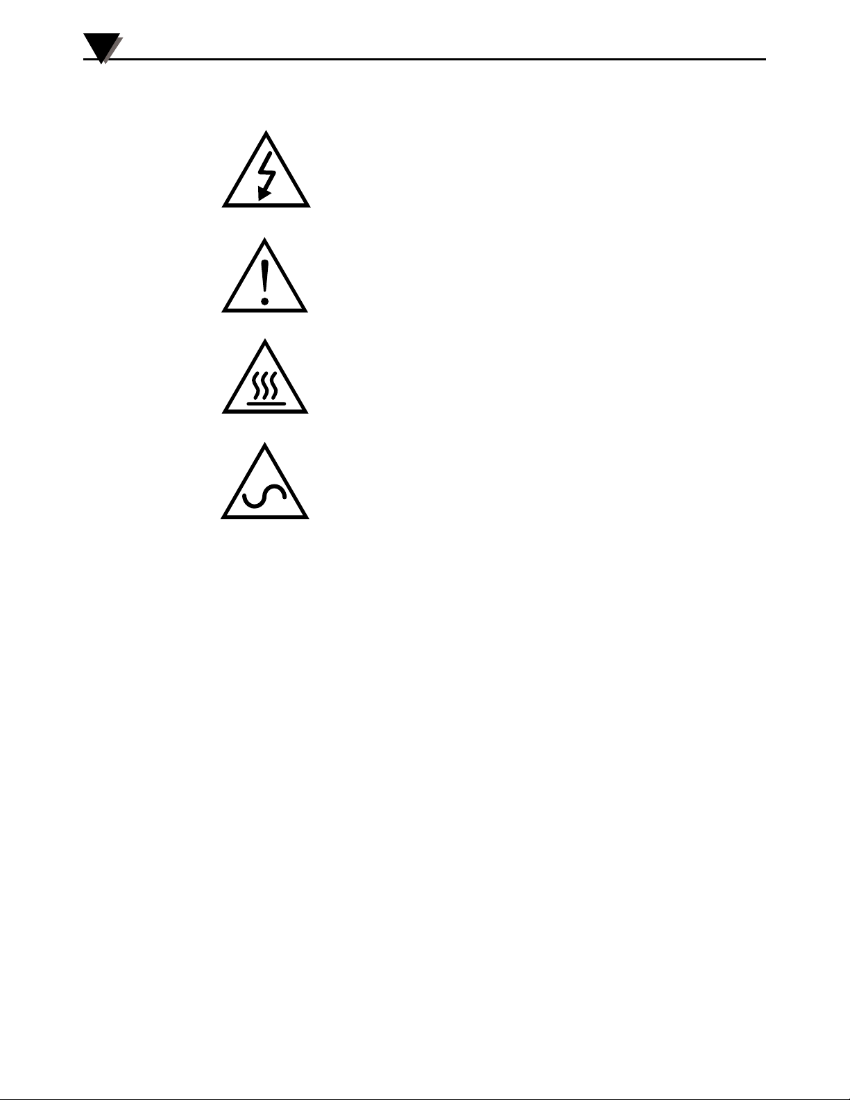
This device is marked with international safety and hazard symbols in
accordance with IEC 1010. It is important to read and follow all precautions and
instructions in this manual before operating or commissioning this device as it
contains important information relating to safety and EMC. Failure to follow all
safety precautions may result in injury and or damage to your calibrator. Use of
this device in a manner not specified by the manufacturer may impair protection
provided within the unit.
NOTE:
1-1
Page 6
1
Introduction
IEC symbols Description
Caution, risk of electric shock
Caution, refer to accompanying
documents
Caution, hot surface
1.3 General Description
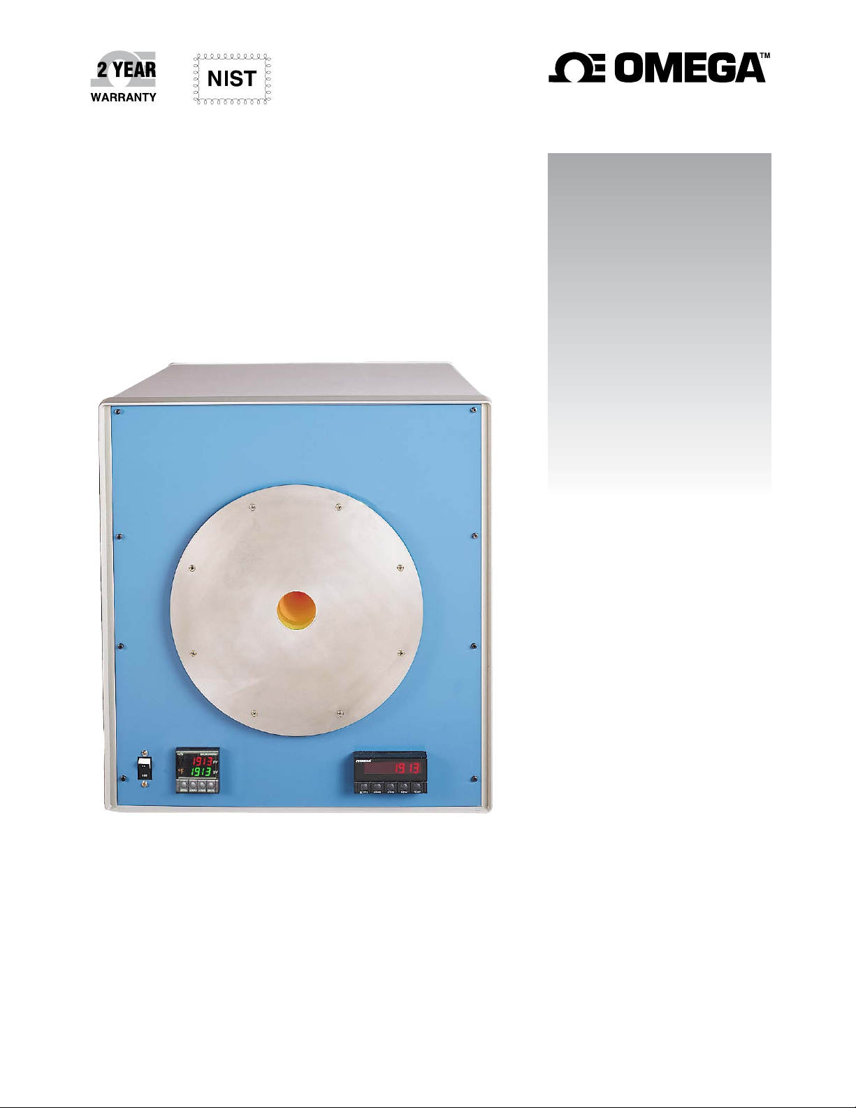
The Model BB705 is a very high temperature, laboratory grade, blackbody
calibration source. The calibrator is used to test and calibrate infrared
pyrometers. The calibration source, with built-in PID digital controller,
maintains an accuracy of 0.25% of reading ±1°C. The cavity has a 44.5 mm (1.75")
diameter aperture with an emissivity of 0.99 and can be set to any temperature
from 100 to 1046°C (212 to 1915°F).
230 VAC @50/60Hz (European Models)
115 VAC @50/60Hz (Domestic Models)
Figure 1. IEC symbols
1-2
Page 7

Section 2 - Installation
2.1 Unpacking and Inspection
Remove the packing list and verify that you have received all your equipment.
If you have any questions about the shipment, please call our Customer Service
Department at
1-800-622-2378 or 203-359-1660. We can also be reached on the Internet at
www.omega.com
e-mail: [email protected]
When you receive the shipment, inspect the container and equipment for any
signs of damage. Note any evidence of rough handling in transit. Immediately
report any damage to the shipping agent.
The carrier will not honor any damage claims unless all shipping material is saved for inspection.
After examining and removing contents, save packing material and carton in
the event reshipment is necessary.
NOTE:
Installation
2
The following items are supplied in the box:
Item: OMEGA Part Number:
BB705 Blackbody Calibration Source BB705 or BB705-230
User Manual M-3638
Calibration Certificate CAL-3 (3 DATA
POINTS)
Power Cord 200-0028 (Domestic),
200-0107 (International)
2.2 Mounting
Mount the unit on a bench, table top or shelf in a horizontal position and operate
at least ten inches from any air obstructions to the fan, front panel, rear panel,
sides and top of the unit, in an ambient environment between the specified 0 to
35°C (32 to 95°F).
2.3 Ambient Temperature
The target cavity of the BB705 can achieve any temperature within the
specified temperature range when being operated in normal specified ambient
temperature environments. The maximum specified target plate temperature of
1046°C (1915°F) can be achieved over the entire specified ambient temperature
range of 0 to 35°C (32 to 95°F).
2-1
Page 8

2
Installation
2.4 Power Connection
Standard (115 VAC~, 50/60 Hz Models)
The BB705 comes with a standard North American 3-prong AC power cord. Do
not use any other power cord other than the one provided. This cord provides
the proper grounding and has been safety tested by the proper safety agencies.
International (230 VAC~, 50/60 Hz Models)
On 230 VAC~, 50/60Hz models an International style power cord with the
proper color code and approvals is provided with stripped wire ends for
connection to the proper connector used in your country or local area, this
connector is not provided.
• Electrical connections and wiring should be performed only by suitably trained personnel.
• Be sure that the line voltage powering your unit does not go above or below 10% of the rated
voltages specified above.
CAUTION:
2-2
Page 9
Section 3 - Operation
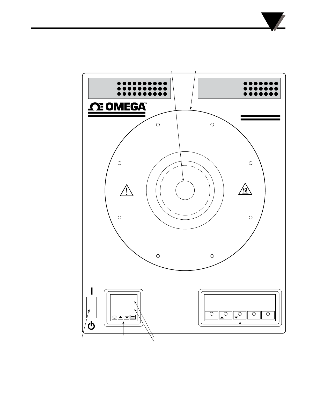
3.1 Front Panel Controls and Indicators
Operation
3
C
U
A
C
A
U
T
CAVITY
APERTURE
C
:
N
O
I
T
I
O
N
:
C
V
A
A
V
APERTURE
PLATE
T
Y
I
M
M
I
Y
T
BLACK POINT
Blackbody
Calibrator
A
Y
B
E
H
O
T
T
O
H
E
B
Y
A
TM
BB705
POWER
SWITCH
1000 C
1000 C
CONTROLLER
SET VARIABLE
PROCESS VARIABLE
Figure 2. Front Panel
1000.00 C
SETPTS /MAX /DEV MENU
TEMPERATURE REFERENCE METERTEMPERATURE
PRESET
3-1
Page 10

3
Operation
Power Switch
The power switch has two positions, “ON and “STANDBY.”
ON STANDBY
The fans are activated whenever the unit is plugged into a live power outlet.
Regardless of whether the power switch is on, the fans will run for a period of 2
hours or until the power is turned on. The fans will remain on as long as the unit
is turned on. Once the unit is switched from “ON” mode to “STANDBY”
mode
the fans will again run for 2 hours. Never disconnect the power cord
while the unit is still cooling down. A safety hazard may result and the unit
may get damaged.
Temperature Controller:
The controller is used for setting the desired temperature of the cavity. The
controller display provides process temperature and setpoint temperature. A
4 button keypad is used to set the setpoint temperature and change engineering
units.
Temperature Reference Meter:
The temperature reference meter displays the cavity temperature with high
precision. See Section 3.5 for parameter programming information.
3.2 Heater Cavity and Aperture Plate
The heater cavity is a near ideal blackbody source. The emissivity of the cavity
is 0.99. When calibrating an IR pyrometer, hold the pyrometer perpendicular
to the aperture for optimal performance. The proper distance between the IR
pyrometer and the target plate depends on the field of view of the pyrometer.
If the pyrometer is too far away, it will scan unwanted surfaces outside of the
perimeter of the target plate. Holding the pyrometer too close could introduce
undesirable heat to the IR detector of the pyrometer. Always aim the gun
toward the center of the cavity cone. Then search for the hottest spot. Use the
pyrometer’s peak detector feature.
3-2
Page 11
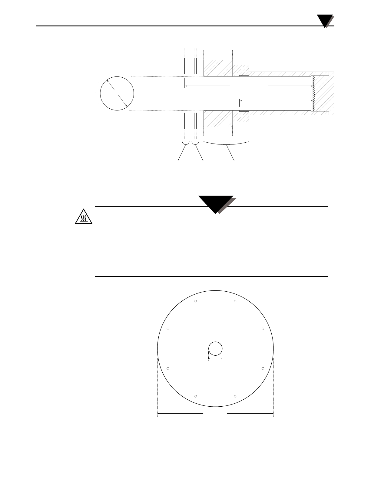
FACE VIEW CROSS-SECTION VIEW
ID=1-3/4
200 ± 3.18 (7-7/8 ± 1/8)
123.83 ± 0.79 (4-7/8 ±1/32)
Operation
HEATER CAVITY
DIMENSIONS mm (in)
3
APERTURE
PLATE
FRONT
PANEL
INSULATORS
Figure 3. Heater Cavity Dimensions
WARNING:
WARNING:
• The BB705’s heater cavity can be set to very high temperatures. Exercise extreme caution when
operating the unit. Keep hands and fingers away from the heater cavity aperture and aperture
plate area. Keep flammable products such as paper, plastics and clothing far from the BB705.
• The BB705 is a Class II instrument. It is intended to be operated in laboratory environment only.
Never operate the unit outside or around children.
• Nothing should come in contact with the heater cavity aperture or aperture plate. Even when the
unit is off.
• Never unplug the unit while it is on or during “Cool-Down.”
The 8 equally spaced mounting holes are 0.457 mm (0.180") in diameter and are
on an 293.6 mm (11.56") diameter bolt circle. The plate is anodized aluminum.
57.15
(2-1/4)
THRU
330.2 (13.0)
Figure 4. Aperture Plate
3-3
Page 12
3
METER RS232
Operation
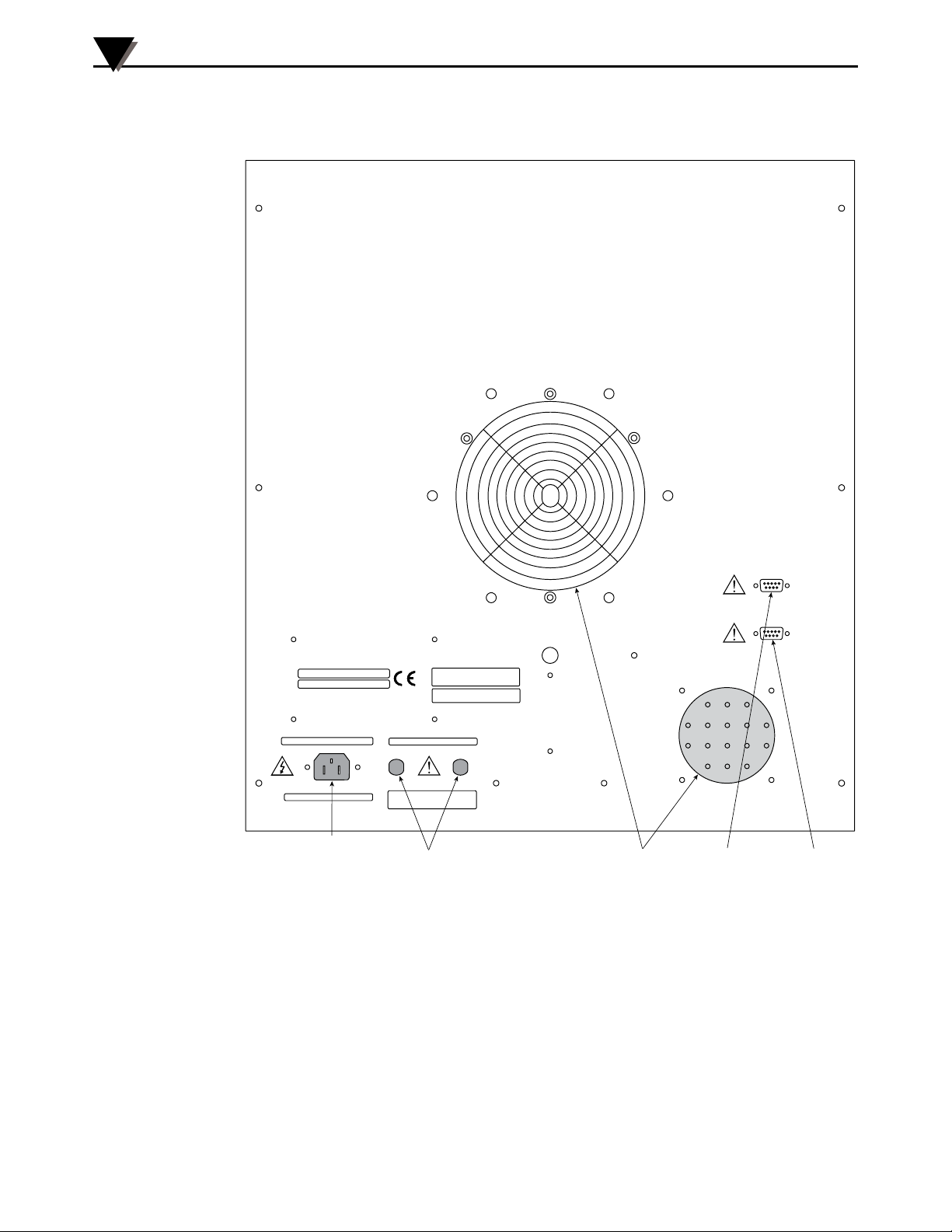
3.3 Rear Panel
MODEL NO. BB705-230VAC
SERIAL NO.
208-240 VAC~50/60 Hz, 1100W
INSTALLATION CATEGORY II
POWER
INLET
MADE IN U.S.A.
OMEGA ENGINEERING, INC.
STAMFORD, CT 06907-0047
203-359-1666
www.omega.com
e-mail: [email protected]
FUSE: (2 EA.) T6.3A 250V
CAUTION: FOR CONTINUED PROTECTION AGAINST
THE RISK OF FIRE REPLACE WITH ONLY THE SAME
TYPE, RATING AND SIZE OF FUSE. DISCONNECT
POWER FROM SOURCE BEFORE CHANGING FUSE.
FUSES
FANS
Figure 5. Rear Panel
COMMUNICATION PORT
CONTROLLER
COMMUNICATION PORT
REFERENCE METER
CONTROLLER
RS232
RS-232
RS-232
REFERENCE
3-4
Page 13

Operation
3
AC Power Inlet:
The customer connects the power cord to the AC Power Input. As a safety
precaution, the power cord cannot be connected if the fuse compartment is open.
Refer to Section 5.3 for information on fuse replacement.
Fuses:
The fuses are replaceable by removing the fuse cap with a screwdriver. Domestic
models (115V) have
1
⁄4 x 11⁄4” fuse, International models (230V) have two 5 x 20
mm fuses. Be sure to disconnect the power cord before checking or replacing
fuses. See Section 5.3 for fuse specification information.
RS-232 Communication Ports:
The female DP-9 ports allow the customer to make a 3-wire RS-232 interface
with the controller and the reference meter. A detailed description of this part is
described in Section 4.
3.4 Controller Settings
3.4.1 Changing the Temperature Setpoint
Definitions:
Process Variable:
This field displays the current temperature of the target plate.
Setpoint Temperature:
This field displays the desired target plate temperature. Once the target plate
reaches this desired temperature, both displays will read the same value.
Controller Keys:
Parameter/Access Key:
Press to scroll through menu parameters
Raise Key:
In the normal operating mode, press this key to increase the setpoint
temperature. In the programming mode, use this key to increase the menu level
or the value of a selected parameter.
Lower Key:
In the normal operating mode, press this key to decrease the setpoint
temperature. In the programming mode, use this key to decrease the menu level
or the value of a selected parameter.
Mode Key:
Press to save settings and exit a menu level.
The layout of the front panel is shown in Figure 2. The BB705 incorporates a
PID digital temperature controller. In the default mode, the digital displays the
process variable (PV) as well as the setpoint variable (SV). The process variable
in the BB705 is the current measured temperature of the heater cavity. The
3-5
Page 14

3
Operations
setpoint variable is the desired temperature the user has set. Setpoint
temperature can be changed by depressing the “
” and “ ” keys. Holding
either of these keys for an extended period will cause the setpoint temperature to
advance more quickly to a desired value. Three scanning speeds are provided:
slow, medium and fast. The minimum and maximum setpoints are locked at 0
and 1046°C (32 and 1915°F), respectively. While these max. and min. settings
are changeable (see “Changing Controller Parameter Settings,” Section 3.4.2),
it is strongly advised not to adjust these parameters.
NOTE:
P.I.D. Control:
Proportional, integral, derivative control ( P.I.D.) is a temperature control algorithm used in high-end
temperature controllers. The controller causes the process to attain the desired temperature by turning
the process on or off. The process may be a heater or refrigerator. As the process temperature
approaches the setpoint temperature the hot or cold process will be pulsed to reduce the corrective
measures and minimize overshooting. The controller provides a visual representation of the process
status through LED indicators. An indicator may be lit continuously, blink or shut off entirely to indicate
that the process is on, being pulsed, or off, respectively.
3.4.2 Changing the Controller Parameter Settings
The BB705’s controller operates at its optimum performance when left with the
factory parameter settings. The only internal parameter that the operator may
need to change is the engineering units (°C or °F) or serial communications
parameters. If the parameter settings are accidentally altered or become lost,
the parameters should be re-programmed in according to the factory default
settings. Below are two diagrams: a) menu hierarchy with factory default
settings b) programming procedure.
Menu 00 Menu 01 Menu 02 Menu 03 Menu 04 Menu 05
Key Lock SETPOINT Ac.Cd = 02 Ac.Cd = 03 Ac.Cd = 04 Ac.Cd = 05
Ac.Cd
Gn.o1 193Ŧ ALr1 1925 id.no 01 SnSr S
Gr.o2 ALr2 bAUd 12.o.7 Sn.00
rAtE 29
rSEt 146Ŧ Cy.t2 CAL.H FILt
H.Hys SP.tt OFF OUt.1 Ht.P
HyS.1 L.SP.L 212 OUt.2 Alr
C.HyS L.SCL CoL.t nor
HyS.2 U.SP.L 1915 A1.HL HI
C.SPr H.SCL A1.Pd Pr
SPr.2 A1.OP LAt
dPnG NI A2.HL Hl
A2.Pd Pr
Ŧ
A2.OP OFF
Unit F
Suggested starting values shown above.
Actual values will be determined and
automatically updated by Autotune function.
Ŧ
Cy.t1 01 CAL.L dEC.P
3-6
Figure 6. Controller Default Parameters
Page 15

Operation
3
1. Press the
2. Use the
once.
and keys to select menu level.
3. Once the the desired menu appears, scroll through the parameters of that
menu using the key.
4. Use the
5. Press
and keys to adjust a given parameter.
to save settings and exit programming mode.
6. Re-enter the programming mode (from step #1) to access other menus.
Figure 7. Controller Programming Procedures
3.5 Temperature Reference Meter Settings
The high accuracy temperature reference meter has been calibrated at the factory
and need not be adjusted by the user except for setting the engineering units (°F
or °C), enabling or disabling the units indicator (ON/OFF), or setting the display
resolution (XXXXXX, XXXXX.X or XXXX.XX).
To change the engineering units:
1. Press the MENU key until the display reads “RDG.CNF.”
2. Press the MIN key until the display reads “RDG.5.”
3. Set this parameter as desired using the MAX key (“0”=°C, “1”=°F, “2”=°K).
4. Press MENU to store the settings.
5. Press RESET twice to save settings and return to normal operation mode.
To turn the engineering units indicator on or off:
1. Press the MENU key until the display reads “RDG.CNF.”
2. Press the MIN key until the display reads “RDG.6.”
3. Set this parameter as desired using the MAX key (“0”=units not displayed,
“1”=units displayed).
4. Press MENU to store the settings.
5. Press RESET twice to save settings and return to normal operation mode.
To select the display resolution:
1. Press the MENU key until the display reads “DEC PT.”
2. Press the MAX key to choose the desired resolution (FFFFFF, FFFFF.F, or
FFFF.FF).
3. Press MENU to store the settings.
4. Press RESET twice to save settings and return to normal operation mode.
3-7
Page 16

3
TEMPERATURE C (F)
100 (212) 500 (932) 1000 (1832)
100 (212) 30 80
Operations
3.6 Target Cavity Temperature Transition Table
The BB705 heat-up and cool-down characteristics are illustrated in the following
table. The table illustrates the approximate time required to make a transition
from one heater cavity temperature to another. First, determine the current
heater cavity temperature and go to the corresponding row. Now, decide
the new heater cavity temperature and go to the appropriate column. Note
that there are X’s along the diagonal where original and target heater cavity
temperatures are the same.
TO:
FROM:
URE
Figure 8. Approximate Target Plate Temperature Transition Times
3-8
Page 17
Section 4 - RS232 Communications
The controller and reference meter provides for bi-directional data transfer via
a three conductor cable consisting of signal ground, receive input, and transmit
output. It is recommended that less than fifty feet of shielded cable be used
between the computer and this instrument. This will assure performance
of the BB705 to EN61326 standards, under the E.M.C. Note that multiple
instruments cannot be tied to the same port in this configuration. The RS232 port
is optically isolated to eliminate ground loop problems.
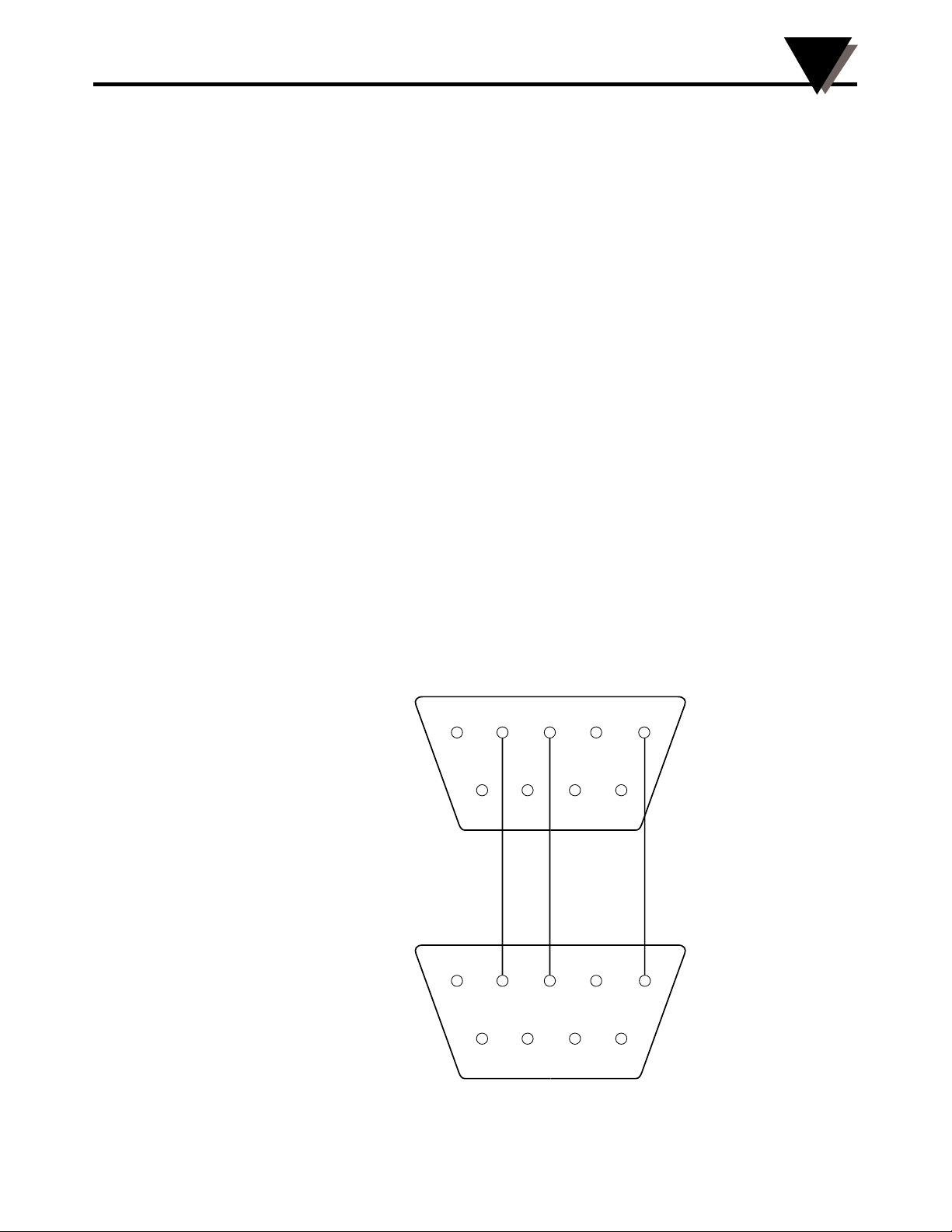
In Figure 9 is a pinout diagram for the serial port of the BB705 as well as the
pinout for a 9-pin PC serial port. Use a straight DB9 (female) to DB9 (male)
connector cable to connect your computer to the BB705. The cable should be
attached only when the computer and BB705 are off.
Only parameters in the parameter list should be modified or queried via the
serial port. Other parameters should be viewed or queried from the controller,
directly. It is highly recommended that baud rate for the controller be modified
on the controller, directly. Note that both the BB705 and the computer must be
communicating with the same serial communications parameters to establish a
working communication link.
RS232 Communications
4
The serial communications feature can be tested using terminal emulation
package. Note that this controller does not time out waiting for the next
character to be transmitted. Be sure not to use the XON/XOFF or hardware
handshaking. Lastly, it should be noted that following a complete transmission
to the BB705, a response it sent back. If the message was valid, the changed or
queried parameter is echoed back (following the same format). If the message
was not according to acceptable format or was attempting to force a parameter
out of range, an “ERROR” message is echoed.
1
BB705
BLACKBODY
CALIBRATOR
(CONTROLLER
OR REFERENCE
METER)
2345
6789
RX
TX
TX
RX
GND
GND
COMPUTER
SERIAL
PORT
(RS232)
Figure 9. Connecting a PC to the BB705’s Controller/Reference Meter Serial Port
12345
6789
4-1
Page 18

4
RS232 Communications
Parameter List (only relevant parameters shown):
PAR#: Parameter: Range/Units:
00 Process Temp. Input determined
01 Setpoint Input determined
19 Baud Selection bAUd
Baud Selections:
Code: Baud: Parity: Data Bits: Stop Bits:
3.o.7 300 odd 7 2
6.o.7 600 odd 7 2
12.o.7 1200 odd 7 2 (factory default settings)
24.o.7 1200 odd 7 2
3.n.8 300 no 8 1
6.n.8 600 no 8 1
12.n.8 1200 no 8 1
24.n.8 2400 no 8 1
General Message Format:
#[controller id][command][parameter number]<new value><units>[CR/LF]
Definitions:
# - This character initiates an “escape sequence” that the controller will
recognize.
[controller id] – Up to 2 numeric characters, “00” to “99” (factory default=”01”)
[command] – 1 character, upper case or lower case
“R” – To read a parameter from the controller
“M” – To temporarily modify a controller parameter (lost upon shutdown)
“E” – To modify a controller param. in non-volatile mem. (saved even after
shutdown)
[parameter #] – Up to 2 numeric characters, “00” to “99”
<new value> - This control word is used only when entering or modifying a
parameter. Up to 6 characters may be entered. The first character
can be a space, a “+”, or a “-”. The next 4 characters are for
entering the new value parameter value. Be sure to use the exact
same field format as is currently being used. (i.e. if the XXX.X
format is used to express temperature, be sure to enter a new
value that conforms to the same format).
4-2
<units> - This optional control word is used to specify units, F for °F, C for °C.
[CR/LF] – Every transmission must be terminated with a carriage return [CR]
character. The line feed [LF] character is optional.
Page 19

Section 5 - Maintenance
5.1 Calibration
This unit has been fine tuned at the factory and calibrated to give optimum
performance of its full temperature range. It is recommended that the unit be
returned annually for re-calibration.
5.2 Cleaning
Remove all electrical connections and power before attempting any maintenance or cleaning. Only
suitably trained trained service persons should perform maintenance or cleaning on the BB705.
5.2.1 Main Body
Only a damp, soft rag with a mild cleaning solution should be used when
cleaning the main body of this unit.
5.2.2 Heater Cavity
Do not attempt to clean the heater cavity through conventional means. The only
type of cleaning the cavity may need is the removal of some soot after burn in.
This fine grain soot can be vacuumed out of the cavity.
CAUTION:
CAUTION:
Maintenance
5
When removing soot from heater cavity, be sure to wear protective goggles. NEVER REMOVE
SOOT FROM A HOT OR WARM CAVITY! Be sure unit has cooled to room temperature and is
disconnected from power source before vacuuming out the soot. Never touch the cavity with your
hand, tools or brushes.
5.2.3 Fan
The fan guard should be cleaned as a minimum annually by using a compressed
air source.
5.3 Fuse replacement
Disconnect all power from source before attempting fuse replacement.
For continued protection against the risk of fire replace with only the same size, type and rating
fuse indicated here and on the rear panel of your unit.
For model: BB705 use 1 ea. 250 VAC~, T12A (Time-Lag, 12 A)
For model: BB705 -230VAC use 2 ea. 250 VAC~, T6.3A (Time-Lag, 6.3A)
WARNING:
CAUTION:
UL APPROVED (
1
⁄4” dia. x 1 1⁄4” long).
VDE APPROVED (5 mm dia. x 20 mm long).
Note that for the BB705-230VAC both fuses need to be checked if there is a
suspicion that a fuse has been blown. One or both fuses may have been damaged.
5-1
Page 20

6
Specifications
Section 6 - Specifications
Heater Cavity Temperature Range: 100°C to 1046°C
(212°F to 1915°F)
Ambient Environmental Conditions:
Temperature: 0°C to 35°C (32°F to 95°F)
Humidity: 0 to 90% RH, non-condensing
Power:
BB705 115 VAC~, 50/60 Hz, 1100W
BB705-230VAC 230 VAC~, 50/60 Hz, 1100W
Internal Control Sensor: Platinum Thermocouples
Accuracy: ±1°C, ±0.25% rdg
(±1.8°F, ±0.25% rdg)
Ref. Meter Display Accuracy: ±0.06°C (over entire range)
Resolution: 0.01° (on temperature reference meter)
Overall System Stability: ±0.4°C per 8-hr. period
Target Plate Emissivity: 0.99
Cavity Aperture Diameter: 44.4 mm (1.75")
Heat-Up Time: 80 minutes from 100°C to 1000°C
(from 212°F to 1832°F)
Dimensions: 566 W x 520 H x 600 D
(22.3 W x 20.5 H x 23.6" D)
Weight: 31 kg. (68 lb.)
Installation Category II
6-1
Page 21

Section 7 - Troubleshooting Guide
Problem Solution
1. Unit will not turn on. a. Check all electrical connections.
b. Check rear panel fuses.
c. Unit requires service, contact our
2. Unit turns on but the target a. Check that you have entered a
plate will not get hot. will setpoint above the ambient
temperature.
b. Verify that the controller is set to its
c. Unit requires service, contact our
d. Unit has been operated outside of
Troubleshooting Guide
customer service department.
factory default settings.
customer service department.
operating range. Safety cutoff switch
has disabled heater. Unit should be
sent back to factory for reset and safety
check.
7
3. Controller display shows “Error” a. Unit requires service, contact our
and the target plate will not get customer service department.
hot or cold.
4. Target plate temperature will a. Verify that the controller is set to its
not stabilize to within ±0.5°F of factory default settings.
the setpoint temperature.
b. Unit requires service, contact our
customer service department.
5. Controller has no output. a. Controller may be in STANDBY mode.
Pressing buttons has No effect. Hold down the
TUNE blinks on the display. until “TUNE”
stops blinking.
6. Controller has no output. a. Controller may be in LOCK mode.
Controller does not Respond Hold down the
to any keypresses. until “Ac.Cd”
is displayed. Change to a menu level
other than level 1 and exit the menu
selection mode by pressing the
once.
key continuously
key continuously
key
7-1
Page 22

8
Glossary of Terms Used in This Manual
Section 8 - Glossary of Terms Used in This Manual
Blackbody
A theoretical object that radiates the maximum amount of energy at a given
temperature, and absorbs all the energy incident upon it.
Calibration
The process of adjusting an instrument or compiling a deviation chart so that its
reading can be correlated to the actual value being measured.
Emissivity
The ratio of energy emitted by a surface to the energy emitted by a blackbody at
the same temperature.
IEC
International Electrotechnical Commission
Infrared (IR)
A range of the electromagnetic spectrum extending beyond red visible light from
760 nanometers to 1000 microns.
NIST
National Institute of Standards and Technology
PID
Proportional, Integral, Derivative. A three mode control action where the
controller has time proportioning, integral (auto reset) and derivative rate action.
RTD
Resistance temperature detector
8-1
Page 23

The OMEGA Family of Blackbody Calibrators
The OMEGA Family of Blackbody Calibrators
Listed below is a selection guide of OMEGA’s current line of blackbody calibration
sources in addition to the one you have selected. This family of rugged, portable and
accurate calibrators cover a wide range of temperatures, target plate sizes and features
making them perfect for infrared pyrometer field service testing and laboratory
calibrations.
BB701 Hot/Cold Blackbody Calibration Source
Calibration Range: -18 to 149°C (0 to 300°F) Accuracy: ±0.8°C (±1.4°F)
Emissivity: 0.95 Ambient Temp.: 4 to 43°C (40 to 110°F)
Cavity Size: 63.5 mm (2.5 in.) Power: 115/230V, 50/60 Hz, 175W
BB702 Blackbody Calibration Source
Calibration Range: 32 to 215°C (amb. 90 to 420°F) Accuracy: ± 0.5°C (±0.9°F), ±0.25% rdg.
Emissivity: 0.95 Ambient Temp.: 5 to 45°C (41 to 113°F)
Cavity Size: 63.5 mm (2.5 in.) Power: 115/230V, 50/60 Hz, 75W
BB703 Mini Blackbody Calibration Source
Calibration Range: 32 to 400°C (90 to 752°F) Accuracy: ±1.4°C (±2.5°F)
Emissivity: 0.95 Ambient Temp.: 0 to 40°C (32 to 104°F)
Cavity Size: 28.6 mm (1.125 in.) Power: 115/230V, 50/60 Hz, 175W
9
BB704 4” Target Plate Blackbody Calibration Source
Calibration Range: 100 to 400°C (212 to 752°F) Accuracy: ±0.8°C (±1.4°F)
Emissivity: 0.95 Ambient Temp.: 0 to 50°C (32 to 122°F)
Cavity Size: 101.6 mm (4 in.) Power: 115/230V, 50/60 Hz, 425W
BB705 Laboratory Grade Blackbody Calibration Source
Calibration Range: 100 to 1046°C (212 to 1915°F) Accuracy: ±1.0°C (±1.8°F), ±0.25% rgd
Emissivity: 0.99 Ambient Temp.: 0 to 35°C (32 to 95°F)
Cavity Size: 44 mm (1.75 in.) Power: 115/230V, 50/60 Hz, 1100W
BB-4A High Temperature Blackbody Calibration Source
Calibration Range: 100 to 982°C (212 to 1800°F) Accuracy: ±1.0°C (±1.8°F), ±0.25% rdg
Emissivity: 0.99 Ambient Temp.: 0 to 50°C (32 to 122°F)
Cavity Size: 22.2 mm (0.88 in.) Power: 115/230V, 50/60 Hz, 400W
For a complete, updated specification sheet and price on any of the calibrators listed here visit our
website at www.omega.com. Please call our sales or customer service department for information
and pricing on any new models available.
9-1
Page 24

NOTES:
BB705 Very High Temperature Laboratory Blackbody Calibration Source
9-2
Page 25

WARRANTY/DISCLAIMER
OMEGA ENGINEERING, INC. warrants this unit to be free of defects in materials and workmanship for a
period of 25 months from date of purchase. OMEGA’s WARRANTY adds an additional one (1) month grace
period to the normal two (2) year product warranty to cover handling and shipping time. This ensures
that OMEGA’s customers receive maximum coverage on each product.
If the unit malfunctions, it must be returned to the factory for evaluation. OMEGA’s Customer Service
Department will issue an Authorized Return (AR) number immediately upon phone or written request.
Upon examination by OMEGA, if the unit is found to be defective, it will be repaired or replaced at no
charge. OMEGA’s WARRANTY does not apply to defects resulting from any action of the purchaser,
including but not limited to mishandling, improper interfacing, operation outside of design limits,
improper repair, or unauthorized modification. This WARRANTY is VOID if the unit shows evidence of
having been tampered with or shows evidence of having been damaged as a result of excessive corrosion;
or current, heat, moisture or vibration; improper specification; misapplication; misuse or other operating
conditions outside of OMEGA’s control. Components in which wear is not warranted, include but are not
limited to contact points, fuses, and triacs.
OMEGA is pleased to offer suggestions on the use of its various products. However,
OMEGA neither assumes responsibility for any omissions or errors nor assumes liability for
any damages that result from the use of its products in accordance with information provided
by OMEGA, either verbal or written. OMEGA warrants only that the parts manufactured by the
company will be as specified and free of defects. OMEGA MAKES NO OTHER WARRANTIES OR
REPRESENTATIONS OF ANY KIND WHATSOEVER, EXPRESSED OR IMPLIED, EXCEPT THAT OF
TITLE, AND ALL IMPLIED WARRANTIES INCLUDING ANY WARRANTY OF MERCHANTABILITY
AND FITNESS FOR A PARTICULAR PURPOSE ARE HEREBY DISCLAIMED. LIMITATION OF
LIABILITY: The remedies of purchaser set forth herein are exclusive, and the total liability of
OMEGA with respect to this order, whether based on contract, warranty, negligence,
indemnification, strict liability or otherwise, shall not exceed the purchase price of the
component upon which liability is based. In no event shall OMEGA be liable for
consequential, incidental or special damages.
CONDITIONS: Equipment sold by OMEGA is not intended to be used, nor shall it be used: (1) as a “Basic
Component” under 10 CFR 21 (NRC), used in or with any nuclear installation or activity; or (2) in medical
applications or used on humans. Should any Product(s) be used in or with any nuclear installation or
activity, medical application, used on humans, or misused in any way, OMEGA assumes no responsibility
as set forth in our basic WARRANTY/DISCLAIMER language, and, additionally, purchaser will indemnify
OMEGA and hold OMEGA harmless from any liability or damage whatsoever arising out of the use of the
Product(s) in such a manner.
RETURN REQUESTS/INQUIRIES
Direct all warranty and repair requests/inquiries to the OMEGA Customer Service Department. BEFORE
RETURNING ANY PRODUCT(S) TO OMEGA, PURCHASER MUST OBTAIN AN AUTHORIZED RETURN (AR)
NUMBER FROM OMEGA’S CUSTOMER SERVICE DEPARTMENT (IN ORDER TO AVOID PROCESSING
DELAYS). The assigned AR number should then be marked on the outside of the return package and on any
correspondence.
The purchaser is responsible for shipping charges, freight, insurance and proper packaging to prevent
breakage in transit.
FOR WARRANTY RETURNS, please have the
following information available BEFORE contacting
OMEGA:
1. Purchase Order number under which the product
was PURCHASED,
2. Model and serial number of the product under
warranty, and
3. Repair instructions and/or specific problems
relative to the product.
OMEGA’s policy is to make running changes, not model changes, whenever an improvement is possible. This affords our
customers the latest in technology and engineering.
OMEGA is a trademark of OMEGA ENGINEERING, INC.
© Copyright 2017 OMEGA ENGINEERING, INC. All rights reserved. This document may not be copied, photocopied,
reproduced, translated, or reduced to any electronic medium or machine-readable form, in whole or in part, without the prior
written consent of OMEGA ENGINEERING, INC.
FOR NON-WARRANTY REPAIRS, consult
OMEGA for current repair charges. Have
the following information available BEFORE
contacting OMEGA:
1. Purchase Order number to cover the COST
of the repair,
2. Model and serial number of the product, and
3. Repair instructions and/or specific problems
relative to the product.
Page 26

Where Do I Find Everything I Need for
Process Measurement and Control?
OMEGA…Of Course!
Shop online at omega.com
TEMPERATURE
MU
Thermocouple, RTD & Thermistor Probes, Connectors,
Panels & Assemblies
MU
Wire: Thermocouple, RTD & Thermistor
MU
Calibrators & Ice Point References
MU
Recorders, Controllers & Process Monitors
MU
Infrared Pyrometers
PRESSURE, STRAIN AND FORCE
MU
Transducers & Strain Gages
MU
Load Cells & Pressure Gages
MU
Displacement Transducers
MU
Instrumentation & Accessories
FLOW/LEVEL
MU
Rotameters, Gas Mass Flowmeters & Flow Computers
MU
Air Velocity Indicators
MU
Turbine/Paddlewheel Systems
MU
Totalizers & Batch Controllers
pH/CONDUCTIVITY
MU
pH Electrodes, Testers & Accessories
MU
Benchtop/Laboratory Meters
MU
Controllers, Calibrators, Simulators & Pumps
MU
Industrial pH & Conductivity Equipment
DATA ACQUISITION
MU
Communications-Based Acquisition Systems
MU
Data Logging Systems
MU
Wireless Sensors, Transmitters, & Receivers
MU
Signal Conditioners
MU
Data Acquisition Software
HEATERS
MU
Heating Cable
MU
Cartridge & Strip Heaters
MU
Immersion & Band Heaters
MU
Flexible Heaters
MU
Laboratory Heaters
ENVIRONMENTAL
MONITORING AND CONTROL
MU
Metering & Control Instrumentation
MU
Refractometers
MU
Pumps & Tubing
MU
Air, Soil & Water Monitors
MU
Industrial Water & Wastewater Treatment
MU
pH, Conductivity & Dissolved Oxygen Instruments
M3638/1217
 Loading...