

Page 1
SERIES AVUL
3-3/16
]
[11.84]
E
®
AIR QUALITY
AIR VELOCITY TRANSMITTERS
3% and 5% of Reading Accuracy, Optional BACnet or Modbus® Communication Protocols
3-49/64
[95.71]
3-33/64
[89.13]
E
O
D
I
V
O
N
L
I
N
1/2 NPS
2-43/64
[67.92]
7-41/64
[194.07]
7-17/64
[184.60]
39/64
[15.32]
Ø15/32
[80.81]
1-19/32
[40.59]
YEAR LIMITED
WARRANTY
31/32 [24.58
2-5/32
[54.82]
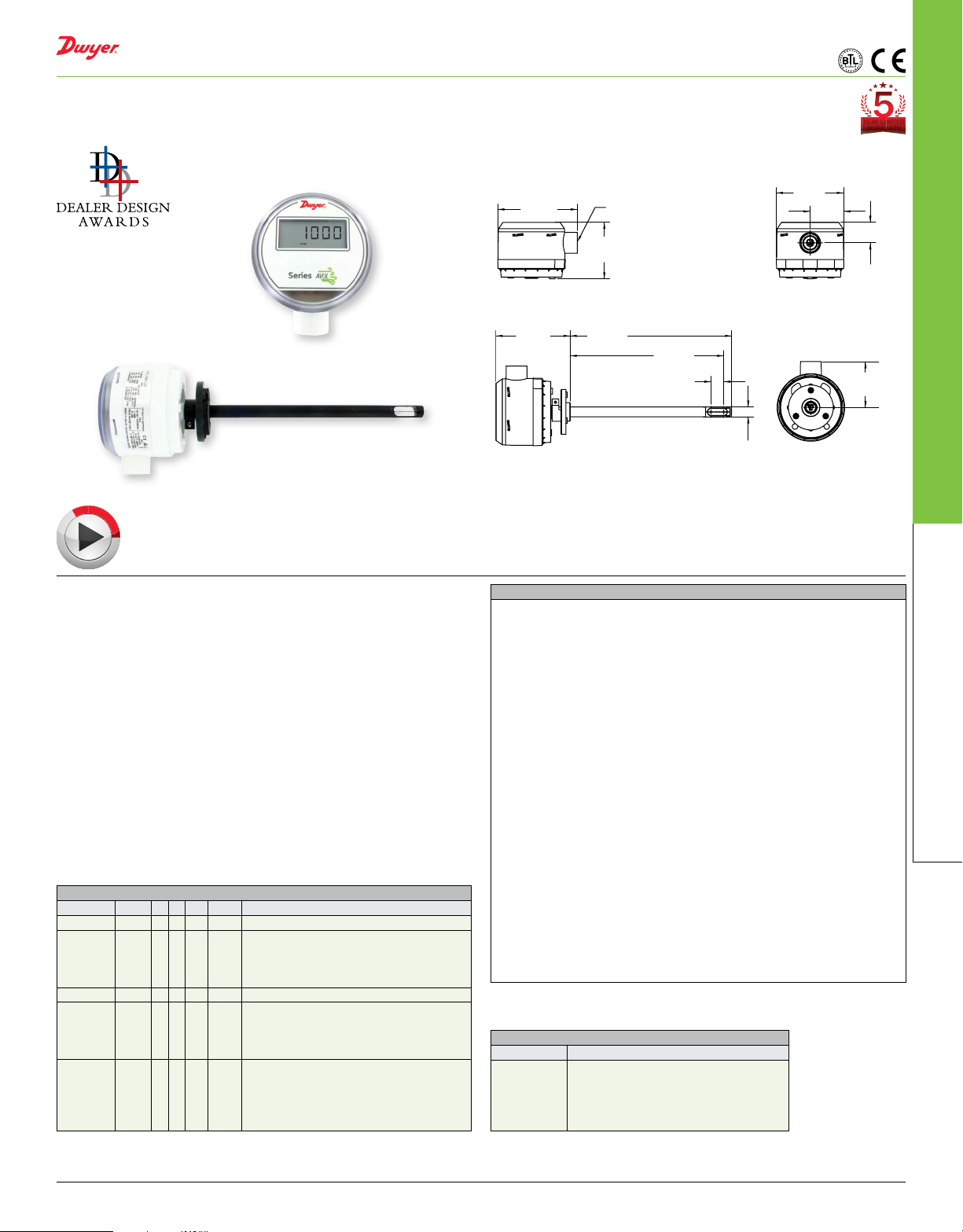
The Series AVUL Air Velocity Transmitters quickly and accurately measures
air velocity or volumetric ow in imperial or metric units. Simultaneous current and
voltage outputs on all models provide universal inputs to monitoring equipment while
the output range, units, and 0 to 5/10 VDC, 4-20 mA output can be congured via local
DIP switches. The optional integral display, or the portable remote display tool, provide
a convenient way to locally monitor process values and congure the unit.
Models are available in 3% and 5% of reading accuracy models to suit a variety
of needs, and the optional BACnet MS/TP or Modbus
®
RTU/ASCII communication
protocol allows units to be daisy-chained while providing access to all of the velocity
and ow data, as well as additional information such as air temperature.
BENEFITS/FEATURES
• Minimal preventative maintenance as sensing element is covered with an
engineered protective coating
• Easy eld setup via the on board dip switches for range and units
APPLICATIONS
• VAV systems
• Building ducts
• HVAC systems
MODEL CHART
Example AVUL -3 D A1 -LCD AVUL-3DA1-LCD
Model AVUL Air velocity transmitter
Accuracy 5
3
±(0.2 m/s + 5% of reading) @ standard
conditions
±(0.2 m/s + 3% of reading) @ standard
conditions
Mounting D Duct mount
Output A1
Analog universal (0-5 VDC, 0-10 VDC, 4-20
mA)
B1
M1
Options FC
Analog + BACnet MS/TP
Analog + Modbus
Factory calibration certicate
GLD
Electrical cable gland
LCD
LCD display
NIST
NIST certicate
SF
Silicone free
®
RTU/ASCII
SPECIFICATIONS
Service: Clean air and non-combustible, compatible gases.
Wetted Materials: Consult factory.
Range: 1000, 2000, 3000, 4000 FPM (5, 10, 15, 20 m/s); Field selectable.
Accuracy: ±(5% of reading + 0.2 m/s) or ±(3% of reading + 0.2 m/s) @ standard
conditions, depending on model.
Temperature Limits: 32 to 122°F (0 to 50°C).
Power Requirements: 24 VDC ±20% or 24 VAC ±20%.
Humidity Limits: 5 to 95% RH, non-condensing.
Output Signals: 4-20 mA, 0-5 VDC, 0-10 VDC.
Response Time (90%): 10 s, typical.
Zero and Span Adjustments: Digital push-buttons.
Output Load Resistance: Current output: 0 to 1100 Ω max.; Voltage output:
Minimum load resistance 1 k Ω.
Current Consumption: 60 mA max.
Display (optional): 5 digit LCD.
Electrical Connections (Analog): Power and output: 4-wire removable European
style terminal block for 16 to 26 AWG.
Communication (optional): Connections: BACnet MS/TP or Modbus
®
RTU/ASCII:
3-wire removable European style terminal block for 16 to 26 AWG; Supported baud
rates: 9600, 19200, 38400, 57600, 76800, 115200.
Device Load: 1/8th unit load.
Electrical Entry: 1/2˝ NPS thread. Accessory (A-151): Cable gland for 5 to 10 mm
diameter cable.
Enclosure Rating: NEMA 4X (IP66).
Mounting Orientation: Flow direction must be parallel to the sensor tip.
Weight: 6.0 oz (160 g).
Compliance: BTL, CE.
ACCESSORIES
Model Description
A-151
A-435-A
A-AVUL-LCD
A-AVUL-MTG
SCD-PS
Cable gland for 5 to 10 mm diameter cable
Remote display tool
Field upgradeable display
Replacement mounting ange
100-240 VAC/VDC to 24 VDC power supply
Air Velocity Transmitters
Modbus® is a registered trademark of Schneider Electric USA, Inc.
DWYER INSTRUMENTS, LLC | dwyer-inst.com
215
 Loading...