

Page 1
Tel +1 (717) 767-6511
Re-Order from
omegamation.com
Omegamation
TM
1-888-55-OMEGA
1-888-55-66342
1-888-55-66342
Fax +1 (717) 764-0839
www.redlion.net
ProducTVity Station™ – PLANT FLOOR COMMUNICATIONS SOLUTION
READY TO DEPLOY PLANT FLOOR VISUALIZATION SYSTEM
CREATES HI-DEFINITION KEY-PERFORMANCE INDICATOR AND
ANDON MESSAGE BOARDS
720p DVI OUTPUT SUPPORTS 720 OR 1080 TVs WITH DVI OR
HDMI INTERFACES
200+ COMMUNICATIONS DRIVERS FOR COMMUNICATING
DIRECTLY WITH PLCs, DRIVES, ETC.
SUPPORTS UP TO 16 CS-SERIES MODULES TO ACCEPT
DIGITAL AND ANALOG SIGNALS
BUILT-IN WEBSERVER ALLOWS REMOTE VIEW OR CONTROL
FROM ANY INTERNET CONNECTED PC
PROVIDES EMAIL AND SMS TEXT MESSAGE ALERTS
INCLUDES 2GB COMPACTFLASH
KPIs AND ANDON EVENTS
SYNCS DATA LOGS TO FTP SERVERS AND MICROSOFT SQL
SERVER
®
32-BIT FLOATING POINT MATH ALLOWS CREATION OF
VIRTUALLY ANY KEY PERFORMANCE INDICATOR
INCLUDES HDMI CABLE AND HDMI/DVI ADAPTER TO SUPPORT
ANY PC OR MONITOR
®
CARD FOR RECORDING
Bulletin No. PTV -X
Drawing No. LP0879
Effective 09/11
GENERAL DESCRIPTION
The ProducTVity Station is a ready to deploy solution for displaying
productivity information, andon messaging, and process status on any off-theshelf TV, PC monitor and even projectors. The PTV leverages over 200
communications drivers via three independent serial ports and an Ethernet port,
to connect and collect data from virtually any PLC, drive, bar code scanner, etc.
Its 720p (1280 x 780 resolution) DVI output is compatible with both 720p and
1080p/i TVs.
The ProducTVity Station’s built-in data-logger can record any keyperformance indicators, as well as andon events for later review. The PTV can
synchronize the log files with any FTP server and/or Microsoft’ s SQL Server for
further analysis.
The ProducTVity Station extends production monitoring to remote personnel
by providing email and text alerts, and its built-in webserver allows productivity
information to be monitored via any networked PC or smart-phone. If enabled,
remote personnel can take partial or full control of the system remotely, allowing
a maintenance person to effect changes without a site visit.
The ProducTVity Station ships complete with a 2GB CompactFlash card, as
well as a DVI to HDMI cable (15´), and HDMI/DVI adapter. The PTV is
programmed with Red Lion’s popular Crimson
®
software.
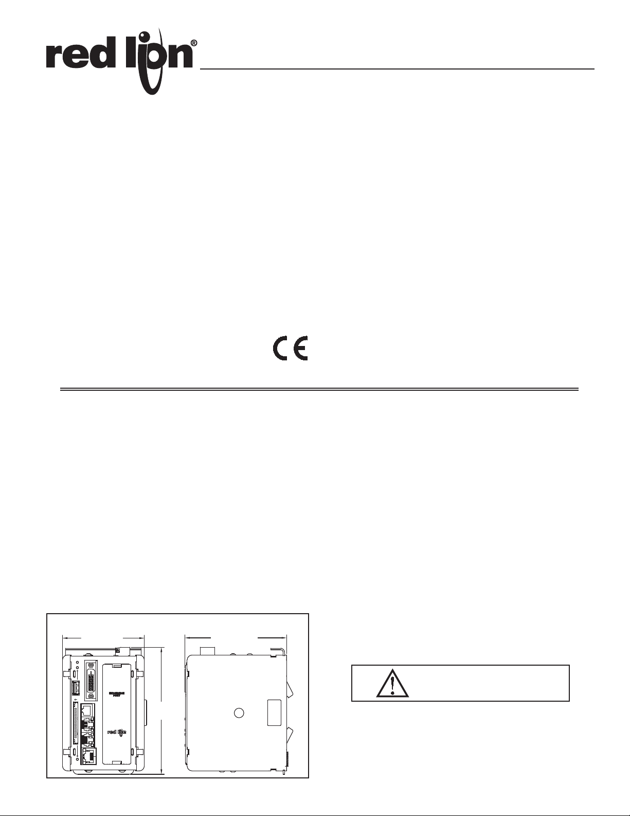
DIMENSIONS In inches (mm)
3.35 (85.2)
STS
USB HOST
DVI
RS232/PG
5.21
(132.4)
4.18 (106.1)
SOFTWARE
The PTV is programmed with Crimson 3.0 software for Windows® XP
Service Pack 2 or later platforms. The software is an easy to use, graphical
interface which allows the configuration of communications, logging, and
stunning visual displays through simple drag and drop steps.
CONTENTS OF PACKAGE
- ProducTVity Station
- Termination Plug
- Terminal Block for connecting power
- Rubber End Cap
- DVI to HDMI Cable (15´)
- HDMI/DVI adapter
- 2 GB CompactFlash card
SAFETY SUMMARY
All safety related regulations, local codes and instructions that appear in the
manual or on equipment must be observed to ensure personal safety and to
prevent damage to either the instrument or equipment connected to it. If
equipment is used in a manner not specified by the manufacturer, the protection
provided by the equipment may be impaired.
Do not use the controller to directly command motors, valves, or other
actuators not equipped with safeguards. To do so can be potentially harmful to
persons or equipment in the event of a fault to the controller. An independent
and redundant temperature limit indicator with alarm outputs is strongly
recommended.
Read complete instructions prior to installation
CAUTION: Risk of Danger.
and operation of the unit.
RS485RS232
ETHERNET
CF
CompactFlash is a registered trademark of CompactFlash Association.
1
Page 2

SPECIFICATIONS
1. POWER: 24 VDC ± 10%
450 mA min. (1 module)
3.4 Amps max. (16 modules + Expansion Card)
Must use NEC Class 2 or Limited Power Source (LPS) rated power supply.
2. COMMUNICATIONS:
USB/PG Port: Adheres to USB 2.0 specification full speed only via Type B
connection.
WARNING - DO NOT CONNECT OR DISCONNECT CABLES
WHILE POWER IS APPLIED UNLESS AREA IS KNOWN TO BE
NON-HAZARDOUS. USB PORT IS FOR SYSTEM SET-UP AND
DIAGNOSTICS AND IS NOT INTENDED FOR PERMANENT
CONNECTION.
USB Host Port: Complies with Universal Serial Bus Specification Rev 2.0.
Support data transfers at full-speed. Hardware over current protected
(0.5 A max).
DVI Port: Digital Visual Interface version 1.3, single link, provides a digital
video feed, with a resolution of 1280 horizontal x 720 vertical pixels,
progressive scan, adhering to CEA-861-E (720 p). DDC support, HDCP is
not supported. Color depth is 32 K.
Serial Ports: Format and Baud Rates for each port are individually software
programmable. Serial ports are individually isolated.
Communication port to port 1500 VAC
Communication ports to power 1000 VDC
Communication ports to earth 1000 VDC
Note: PTV dielectric withstand test per 1 minute. Communication ports:
RS232/PG, RS232 port, RS485 port, Ethernet port and option cards.
RS232/PG Port: RS232 port via RJ12
COMMS Ports: RS422/485 port via RJ45, and RS232 port via RJ12
DH485 TXEN: Transmit enable; open collector, V
V
= 0.5 V @ 25 mA max.
OL
Ethernet Port: 10 BASE-T / 100 BASE-TX
RJ45 jack is wired as a NIC (Network Interface Card). The jack shield is
electrically connected to Earth ground, but the port is isolated.
3. LEDs:
STS – Status LED indicates condition of master.
USB HOST – HOST LED indicates port status/activity.
TX/RX – Transmit/Receive LEDs show serial activity.
Ethernet – Link and activity LEDs.
CF – CompactFlash LED indicates card status and read/write activity
4. MEMORY:
On-board User Memory: 128 Mbytes of non-volatile Flash memory.
On-board RAM: 64 Mbytes
Memory Card: CompactFlash Type II slot for Type I and Type II cards.
5. REAL-TIME CLOCK: Typical accuracy is less than one minute per month
drift. Crimson’s SNTP facility allows synchronization with external servers.
Battery: Lithium Coin Cell. Typical lifetime of 10 years at 25 ºC.
A “Battery Low” system variable is available so that the programmer can
choose specific action(s) to occur when the battery voltage drops below
its nominal voltage.
This unit is NOT field serviceable. All work must be done by a qualified technician.
= 15 VDC,
OH
6. ENVIRONMENTAL CONDITIONS:
Operating Temperature Range: 0 to 45°C
Storage Temperature Range: -30 to +70°C
Operating and Storage Humidity: 80% max relative humidity,
non-condensing, from 0 to 50°C
Altitude: Up to 2000 meters
7. CONSTRUCTION: Case body is black high impact plastic and stainless
steel. For indoor use only. Installation Category II, Pollution Degree 2.
8. POWER CONNECTION: Removable wire clamp screw terminal block.
Wire Gage Capacity: 24 AWG to 12 AWG
Torque: 4.45 to 5.34 in/lb (0.5 to 0.6 N-m)
9. MOUNTING: Snaps onto standard DIN style top hat (T) profile mounting
rails according to EN50022 -35 x 7.5 and -35 x 15.
10. CERTIFICA TIONS AND COMPLIANCES:
SAFETY
Check each module’s specifications to determine system compliance.
IEC 61010-1, EN 61010-1: Safety requirements for electrical equipment
for measurement, control, and laboratory use, Part 1.
ELECTROMAGNETIC COMPATIBILITY
Emissions and Immunity to EN 61326: 2006: Electrical Equipment for
Measurement, Control and Laboratory use.
Immunity to Industrial Locations:
Electrostatic discharge EN 61000-4-2 Criterion B
4kV contact discharge
Electromagnetic RF fields EN 61000-4-3 Criterion A
8kV air discharge
3
10V/m (80 MHz to 1 GHz)
3 V/m (1.4 GHz to 2 GHz)
1 V/m (2 GHz to 2.7 GHz)
Fast transients (burst) EN 61000-4-4 Criterion B
power 2kV
I/O signal 1kV
I/O signal connected to power 2kV
Surge EN 61000-4-5 Criterion B
power 1 kV L to L, 2 kV L to G
signal 1 kV
RF conducted interference EN 61000-4-6 Criterion A
3 Vrms
Emissions:
Emissions EN55011 Class A
Notes:
1. Criterion A: Normal operation within specified limits.
2. Criterion B: T emporary loss of performance fr om which the unit self-r ecovers.
3. Certain modules with analog input and/or output signals may have their
signals deviate during disturbance but self-recover when disturbance is
removed (refer to individual modules for details).
11. WEIGHT: 1.313 lb (596 g)
2
Page 3
HARDWARE
DIN RAIL
5
STS
CF
ETHERNET
RS485RS232
USB HOST
RS232/PG
DVI
INSTALLATION
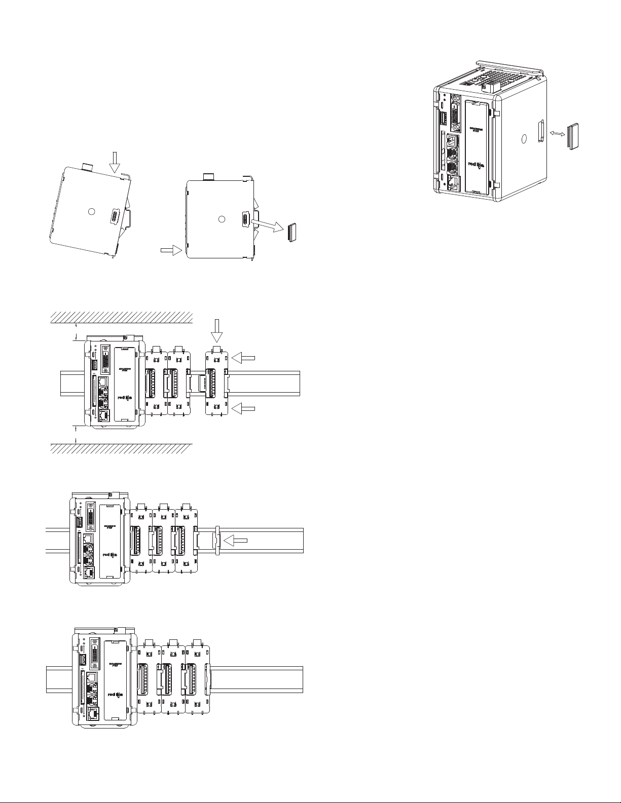
DIN rail should be mounted horizontally so that the unit’s ventilation holes
are vertical in relation to cabinet orientation. A minimum clearance of 1 inch
(25.4 mm) should be maintained above and below the unit in order to ensure
proper thermal regulation. A minimum top clearance of 3.00 inch is needed
when using the USB/PG port.
The unit shall be installed inside a UL Listed Industrial Control Panel or
similar type of enclosure. A minimum 3.2 mm distance shall be maintained
between the hazardous live parts of the equipment and accessible parts of the
fire/electrical enclosure.
1
2
Figure 1 - Attach PTV Station To DIN Rail and Remove
Rubber End Cap
TOP
1.00" min. clearance; 3.00" when using USB/PG port.
STS
DVI
USB HOST
RS232/PG
DEPRESS
3
4
DIN RAIL
RS485RS232
ETHERNET
CF
1.00" min. clearance
4
BOTTOM
Figure 2 - Attach Slave Bases To DIN Rail
REMOVE
PROTOCOL CONVERSION
Mount the PTV as shown under Hardware Installation Figure 1 above. Install
the rubber end cap. The end cap protects
the pins from damage. Configure
the PTV for zero modules.
POWER SUPPLY REQUIREMENTS
It is very important that the power supply is mounted correctly if the unit is
to operate reliably. Please take care to observe the following points:
– The power supply must be mounted close to the unit, with usually not more
than 6 feet (1.8 m) of cable between the supply and the master. Ideally, the
shortest length possible should be used.
– The wire used to connect the PTV’s power supply should be at least 22-gage
wire. If a longer cable run is used, a heavier gage wire should be used. The
routing of the cable should be kept away from large contactors, inverters,
and other devices which may generate significant electrical noise.
– A power supply with an NEC Class 2 or Limited Power Source (LPS) and
SELV rating is to be used. This type of power supply provides isolation to
accessible circuits from hazardous voltage levels generated by a mains
power supply due to single faults. SELV is an acronym for “safety extralow voltage.” Safety extra-low voltage circuits shall exhibit voltages safe
to touch both under normal operating conditions and after a single fault,
such as a breakdown of a layer of basic insulation or after the failure of a
single component has occurred.
Visit www.redlion.net for a complete list of our PSDR Series of NEC Class 2
power supplies.
EMC INSTALLATION GUIDELINES
Although Red Lion Controls Products are designed with a high degree of
immunity to Electromagnetic Interference (EMI), proper installation and wiring
methods must be followed to ensure compatibility in each application. The type
of the electrical noise, source or coupling method into a unit may be different
for various installations. Cable length, routing, and shield termination are very
important and can mean the difference between a successful or troublesome
installation. Listed are some EMI guidelines for a successful installation in an
industrial environment.
1. To reduce the chance of noise spikes entering the unit via the power lines,
connections should be made to a clean source. Connecting to circuits that also
power loads such as contactors, relays, motors, solenoids etc. should be avoided.
2. The unit should be mounted in a metal enclosure, which is properly connected
to protective earth.
3. Use shielded (screened) cables for all Signal and Control inputs. The shield
(screen) pigtail connection should be made as short as possible. The
Figure 3 - Attach Termination Plug*
* Supplied with PTV Station.
connection point for the shield depends somewhat upon the application.
Listed below are the recommended methods of connecting the shield, in order
of their effectiveness.
STS
DVI
USB HOST
RS232/PG
DIN RAIL
RS485RS232
ETHERNET
CF
Figure 4 - Installation Complete
a. Connect the shield to earth ground (protective earth) at one end where the
unit is mounted.
b. Connect the shield to earth ground at both ends of the cable, usually when
the noise source frequency is over 1 MHz.
c. Connect the shield to common of the master and leave the other end of the
shield unconnected and insulated from earth ground.
4. Never run Signal or Control cables in the same conduit or raceway with AC
power lines, conductors feeding motors, solenoids, SCR controls, and
heaters, etc. The cables should be run through metal conduit that is properly
grounded. This is especially useful in applications where cable runs are long
and portable two-way radios are used in close proximity or if the installation
is near a commercial radio transmitter. Also, Signal or Control cables within
an enclosure should be routed as far away as possible from contactors, control
relays, transformers, and other noisy components.
3
Page 4
CBLPROG0
CBLUSB00
OR
Ethernet (Crossover)
OR
STS
CF
ETHERNET
RS485RS232
USB HOST
RS232/PG
DVI
5. Long cable runs are more susceptible to EMI pickup than short cable runs.
Therefore, keep cable runs as short as possible.
6. In extremely high EMI environments, the use of external EMI suppression
devices is effective. The following EMI suppression devices (or equivalent)
are recommended:
Ferrite Suppression Cores for signal and control cables:
Fair-Rite part number 0443167251 (RLC part number FCOR0000)
TDK part number ZCAT3035-1330A
Steward part number 28B2029-0A0
Line Filters for input power cables:
Schaffner part number FN2010-1/07 (RLC part number LFIL0000)
Schaffner part number FN670-1.8/07
Corcom part number 1 VR3
Visit RLC’s web site at www.redlion.net for more information on EMI
guidelines, Safety and CE issues as they relate to Red Lion Controls products.
WIRING
POWER CONNECTION
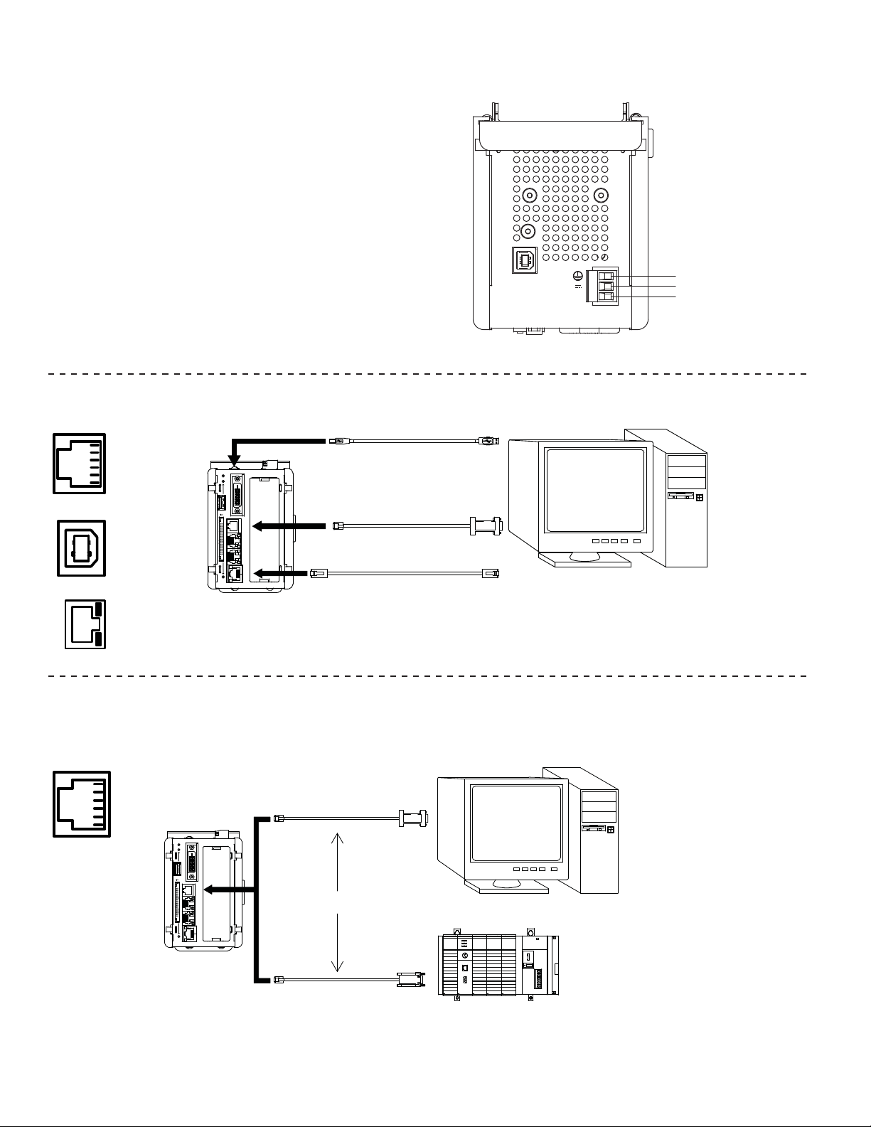
PROGRAMMING PORTS
RS232/PG
CTS
Rx
COMM
COMM
Tx
RS232
RTS
USB/PG
ETHERNET
GREEN/AMBER LED
YELLOW LED
USB/PG
+24V
COMM
CHASSIS GND
+24 V
COMMON
COMMUNICATION PORTS
RS232/PG
CTS
Rx
COMM
COMM
RS232
Tx
RTS
STS
USB HOST
CF
CBLPROG0
DVI
RS232/PG
RS485RS232
ETHERNET
OR
SLC 5/03 CPU
RUN
FORCE
FLT
DH485
BATT
RS232
REM
RUN
PROG
POWER
PWR OUT +24
VDC
USER
POWER
PWR OUT COM
120/240 VAC
VAC NEUT
CHASSIS GND
CBLxxxxx*
4
Page 5
RS232
RTS
Tx
COMM
COMM
Rx
CTS
RS485
TxA
TxB
COMM
TxEN
RxB
RxA
TxA
TxB
RS232
RS485
STS
DVI
USB HOST
RS232/PG
RS485RS232
ETHERNET
CF
CBLxxxxx*
SLC 5/03 CPU
RUN
FORCE
FLT
DH485
BATT
RS232
REM
RUN
PROG
POWER
PWR OUT +24
VDC
USER
POWER
PWR OUT COM
120/240 VAC
VAC NEUT
CHASSIS GND
* Use appropriate communications cable. See Ordering
Information for descriptions of the available cables.
WARNING: Do NOT use a standard DH-485
cable to connect this port to Allen Bradley
equipment.
STS
DVI
USB HOST
RS232/PG
RS485RS232
ETHERNET
CF
CBLxxxxx*
SLC 5/03 CPU
RUN
FORCE
FLT
DH485
BATT
RS232
PROG
REM
RUN
POWER
PWR OUT +24
VDC
USER
POWER
PWR OUT COM
120/240 VAC
VAC NEUT
CHASSIS GND
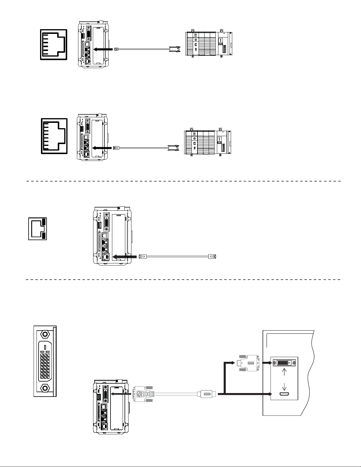
ETHERNET CONNECTION
STS
GREEN/AMBER LED
YELLOW LED
CF
DVI PORT CONNECTION
USB HOST
RS232/PG
RS485RS232
DVI
Standard Ethernet cable
ETHERNET
REMOTE TV, MONITOR
OR PROJECTOR
HDMI-TO-DVI ADAPTER
(INCLUDED)
DVI INPUT
STS
DVI
USB HOST
RS232/PG
RS485RS232
ETHERNET
CF
DVI-TO-HDMI CABLE
(INCLUDED)
OR
HDMI INPUT
5
Page 6
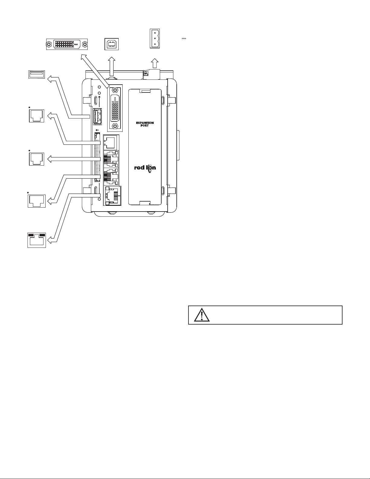
PTV PORT PIN OUTS
DVI VIDEO
2
1 34
USB HOST
Tx
RTS (PIN 6)
COMM
Rx
CTS (PIN 1)
COMM
RS232
RS232/PG PORT
COMMRxB
CTS (PIN 1)
Rx
RTS (PIN 6)
COMM
Tx
RS232
STS
USB/PG
USB HOST
DVI
RS232/PG
RS232
POWER
CONNECTOR
CHASSIS GND
3
24V ± 20%
2
COMMON
1
TROUBLESHOOTING
If for any reason you have trouble operating,
connecting, or simply have questions concerning your
new PTV, contact Red Lion’s technical support. For
contact information, refer to the back page of this bulletin
for phone and fax numbers.
EMAIL: [email protected]
Web Site: http://www.redlion.net
COMMS PORT
TxB (PIN 1)
RxA
TxA
TxEN
COMM
RS485
COMMS PORT
YELLOW
GREEN/
AMBER
LED
ETHERNET (NIC)
TxB
LED
TxA (PIN 8)
CF
RS485
ETHERNET
COMMUNICATING WITH THE PTV STATION
CONFIGURING A PTV
The PTV is configured using Crimson software. Crimson is available as a
free download from Red Lion’s website. Updates to Crimson for new features
and drivers are posted on the website as they become available. By configuring
the PTV using the latest version of Crimson, you are assured that your unit has
the most up to date feature set. Crimson software can configure the PTV through
the RS232/PG port, USB/PG port, Ethernet or CompactFlash. The USB/PG port
is connected using a standard USB cable with a Type B connector.
The driver needed to use the USB port will be installed with Crimson. The
RS232/PG port uses a programming cable made by Red Lion to connect to the
DB9 COM port of your computer. If making your own cable, refer to the “PTV
Port Pin Outs” for wiring information.
The CompactFlash can be used to program a PTV by placing a configuration
file and firmware on the CompactFlash card. The card is then inserted into the
target PTV and powered. Refer to the Crimson literature for more information
on the proper names and locations of the files.
CABLES AND DRIVERS
Red Lion has a wide range of cables and drivers for use with many different
communication types. A list of these drivers and cables along with pin outs is
available from Red Lion’s website. New cables and drivers are added on a
regular basis. If making your own cable, refer to the “PTV Port Pin Outs” for
wiring information.
USB, DATA TRANSFERS FROM THE
COMPACTFLASH CARD
driver must be installed on your computer. This driver is installed with Crimson
and is located in the folder C:\Program Files\Red Lion Controls\Crimson x.x\
Device\ after Crimson is installed. This may have already been accomplished if
your PTV was configured using the USB port.
follow “Mounting the CompactFlash” instructions in the Crimson user manual.
For frequent data transfers it is recommended that the Ethernet connection be
used. Through the Ethernet connection a web page can be set up to view logged
data. Refer to the Crimson manual for details.
Note: The USB port is for system set-up and diagnostics and is not intended for
ETHERNET COMMUNICATIONS
BASE-TX. The PTV’s RJ45 jack is wired as a NIC (Network Interface Card).
For example, when wiring to a hub or switch use a straight-through cable, but
when connecting to another NIC use a crossover cable.
communications.
WARNING - USB PORT IS FOR SYSTEM SET-UP AND
DIAGNOSTICS AND IS NOT INTENDED FOR PERMANENT
CONNECTION.
In order to transfer data from the CompactFlash card via the USB port, a
Once the driver is installed, connect the PTV to your PC with a USB cable, and
Note that using the USB port for frequent data transfers is not recommended.
permanent connection.
Ethernet communications can be established at either 10 BASE-T or 100
The Crimson manual contains additional information on Ethernet
6
Page 7
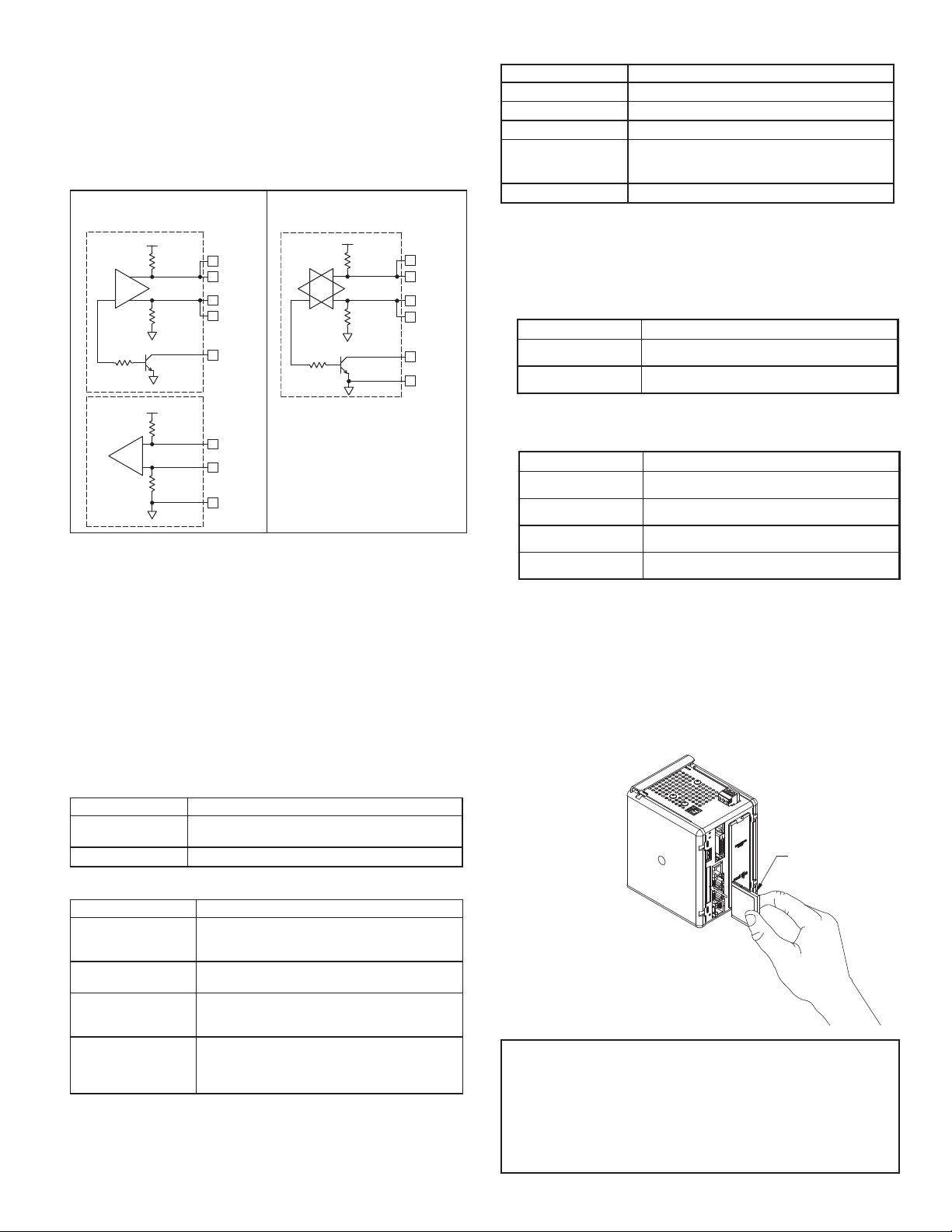
RS232 PORTS
The PTV has two RS232 ports. There is the RS232/PG port and the COMMS
port. Although only one of these ports can be used for programming, both ports
can be used for communications with a PLC. The RS232/PG port can be used
for either master or slave protocols.
RS422/485 PORT
The PTV has one RS422/485 port. This port can be configured to act as either
RS422 or RS485.
RS422/485 4-WIRE
CONNECTIONS
5V
130K
TX
130K
5V
130K
RX
130K
7
1
8
2
5
4
3
6
TxB
TxA
TxEN (OC)
RxB
RxA
GND
RS485 2-WIRE
CONNECTIONS
5V
130K
TX/RX
130K
7
TxB
1
8
TxA
2
TxEN (OC)
5
6 GND
CF LED
LED INDICATION
Off No CompactFlash Card is present.
Steady Valid CompactFlash card is present.
Flashing Rapidly CompactFlash card is being checked.
Unit is writing to the CompactFlash, either because
Flickering
it is storing data, or because the PC connected via
the USB port has locked the drive.
1
Flashing Slowly Incorrectly formatted CompactFlash card present.
1. Do not turn off power to the unit while this light is flickering. The unit writes data
in two minute intervals. Later Microsoft operating systems will not lock the drive
unless they need to write data; Windows 98 may lock the drive any time it is
mounted, thereby interfering with logging. Refer to “Mounting the CompactFlash”
in the Crimson User Manual.
USER COMMUNICATION PORTS - TX/RX LEDS
INDICATIONLED
TransmittingGREEN
ReceivingRED
Note: LEDs are not available on the Programming Port: RS232/PG.
ETHERNET LEDS
INDICATIONLED
Link EstablishedYELLOW (Solid)
Network ActivityYELLOW (Flashing)
Note: All Red Lion devices connect A to A and B to B. Refer to www.redlion.net
for additional information.
DH485 COMMUNICATIONS
The PTV’s RS422/485 COMMS port can also be used for Allen Bradley
DH485 communications.
WARNING: DO NOT use a standard DH485 cable to connect this port to Allen
Bradley equipment. A cable and wiring diagram are available from Red Lion.
LEDS
STS – STATUS LED
The green Status LED provides information regarding the state of the PTV, as
well as the rest of the system. This includes indication of the various stages of
the start-up routine (power-up), and any errors that may occur.
Startup Routine
LED INDICATION
Rapidly Flashing
Steady PTV is operating properly.
Error States
LED INDICATION
1 blink, pause, repeat
2 blinks, pause, repeat
3 blinks, pause, repeat
4 blinks, pause, repeat
PTV is currently running the boot loader and/or being
flash upgraded by Crimson.
One or more slave modules are missing from the
system. PTV and installed modules will perform
normally in this state.
Missing configuration, or configuration being
updated by Crimson.
Quantity of module bases does not match
configuration file. PTV will not communicate with the
modules until the error is corrected.
Termination plug not installed, or one or more bases
are malfunctioning. PTV will not communicate with
the modules until the plug is reinstalled, and power
is cycled.
10 BASE-T CommunicationsGREEN
100 BASE-TX CommunicationsAMBER
COMPACTFLASH® CARD
CompactFlash socket is a Type II socket that can accept either Type I or II
cards. Use cards with a minimum of 4 Mbytes and a maximum of 2 Gbytes with
the PTV’s CompactFlash socket. Cards are available at most computer and office
supply retailers. CompactFlash can be used for configuration transfers, data
logging, and trending.
Information stored on a CompactFlash card can be read by a card reader
attached to a PC. This information is stored in IBM (Windows
®
) PC compatible
FAT16 file format.
CompactFlashInsert Top Side
Towards Left
CompactFlash
(Top Side)
Note: Do not remove or insert
the CompactFlash card while
power is applied.
NOTE
For reliable operation of this and other Red Lion products, one of the
following brands of CompactFlash card must be used...
SimpleTech SMART
®
SanDisk
Not all of the above manufacturers offer CompactFlash cards recognized
to UL standards, which may be required for your application.
®
Modular
Silicon Systems
7
Page 8
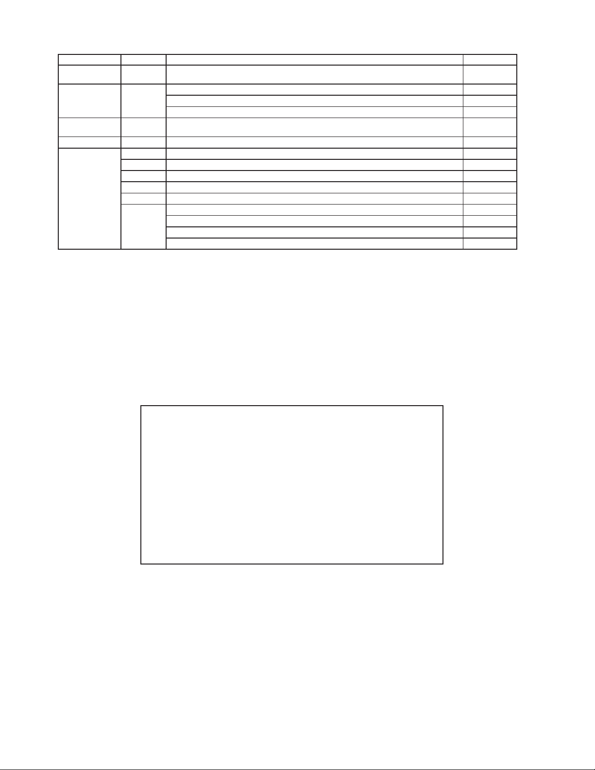
ORDERING INFORMATION
Re-Order from
omegamation.com
Omegamation
TM
1-888-55-OMEGA
1-888-55-66342
1-888-55-66342
TYPE MODEL NO. DESCRIPTION PART NUMBER
ProducTVity
Station
Communications
Cables (10 feet)
Video Cable
(15 feet)
Power Supply PSDR DIN Rail Mounted Power Supply PSDRxxxx
Accessories
Notes:
1
For a complete list of PID modules & data acquisition modules, go to www.redlion.net/link/wp.asp?ID=6162.
2
For a complete list of communications drivers and cables, go to www.redlion.net/link/wp.asp?ID=6163.
3
Industrial grade two million write cycles. SMART Modular Technologies model SG9CF (UL Listed Directory Category NWGQ).
1
PTV
CBL
CBL
XCCN CANopen option card for ProducTVity Station, Modular Controller or Data Station Plus XCCN0000
XCDN DeviceNet option card for ProducTVity Station, Modular Controller or Data Station Plus XCDN0000
XCPB PROFIBUS option card for ProducTVity Station, Modular Controller or Data Station Plus XCPBDP00
XCRS RS232/485 option card for ProducTVity Station, Modular Controller or Data Station Plus XCRS0000
G3CF CompactFlash Card
Plant Floor Communications Solution PTV00000
RS232 Programming Cable CBLPROG0
USB Cable CBLUSB00
Communications Cables
DVI-to-HDMI cable w/HDMI-to-DVI adaptor
(Included in PTV00000)
Rail Stops (Qty 2) RSRSTP00
Replacement Base CSBASE00
Replacement Termination Plug CSTERM00
Replacement Rubber End Cap CSBUNG00
2
3
CBLxxxxx
CBLVID00
G3CFxxxx
The Company warrants the products it manufactures against defects in materials and workmanship for a
period limited to two years from the date of shipment, provided the products have been stored, handled,
installed, and used under proper conditions. The Company’s liability under this limited warranty shall
extend only to the repair or replacement of a defective product, at The Company’s option. The Company
disclaims all liability for any affi rmation, promise or representation with respect to the products.
The customer agrees to hold Red Lion Controls harmless from, defend, and indemnify RLC against
damages, claims, and expenses arising out of subsequent sales of RLC products or products containing
components manufactured by RLC and based upon personal injuries, deaths, property damage, lost profi ts,
and other matters which Buyer, its employees, or sub-contractors are or may be to any extent liable,
including without limitation penalties imposed by the Consumer Product Safety Act (P.L. 92-573) and
liability imposed upon any person pursuant to the Magnuson-Moss Warranty Act (P.L. 93-637), as now in
effect or as amended hereafter.
No warranties expressed or implied are created with respect to The Company’s products except those
expressly contained herein. The Customer acknowledges the disclaimers and limitations contained herein
and relies on no other warranties or affi rmations.
Red Lion Controls
Headquarters
20 Willow Springs Circle
York PA 17406
Tel +1 (717) 767-6511
Fax +1 (717) 764-0839
Red Lion Controls
Europe
Printerweg 10
NL - 3821 AD Amersfoort
Tel +31 (0) 334 723 225
Fax +31 (0) 334 893 793
LIMITED WARRANTY
Red Lion Controls
54, Vishvas Tenement
GST Road, New Ranip,
Ahmedabad-382480 Gujarat, India
Tel +91 987 954 0503
Fax +91 79 275 31 350
India
Red Lion Controls
China
Unit 101, XinAn Plaza
Building 13, No.99 Tianzhou Road
ShangHai, P.R. China 200223
Tel +86 21 6113-3688
Fax +86 21 6113-3683
 Loading...