

Page 1
DIN RaIl MouNteD
MultI-FuNctIoNal
DIgItal tIMeR
AU-AMT Series
l Multifunctional Timer (8 or 18 Functions)
l Universal Voltage 24 to 265 Vac/Vdc
l Wide Time Range: 0.1 Seconds to 999 Hours
l 3 Digit LCD Display for Preset Time and Run Time
l 17.5 mm (0.68") Width
l Models include 2 NO or NO/NC Contacts
The AU-AMT Series of DIN rail mountable digital multi-timers
includes four models featuring 8 or 18 timer functions to offer
highest flexibility in controlling operations. The time range is
adjustable from 0.1 second to 999 hours. An LCD display shows
current run time information.
SPECIFICATIONS
Supply Voltage: 24 to 265 Vac/Vdc (50, 60Hz)
Power Consumption: 10 VA maximum
Timing Range: 0.1 second to 999 hours
Reset Time: 200 ms maximum
Repeat Accuracy: ±0.5%
Output Contact Rating: 8A @ 240 Vac/24 Vdc (resistive)
Electrical Life: 10,000 switching cycles
Mechanical Life: 2,000,000 switching cycles
Operating Temperature: -10 to 55°C (14 to 131°F)
Storage Temperature: -20 to 65°C (-4 to 149°F)
Weight: 85 g (0.14 lb)
Protection Enclosure: IP30
Protection Terminals: IP20
Torque: 0.40 Nm (3.5 lb/inch)
Terminal Wire Size: 0.3 to 2.5 mm2 (22-14 AWG)
Setting
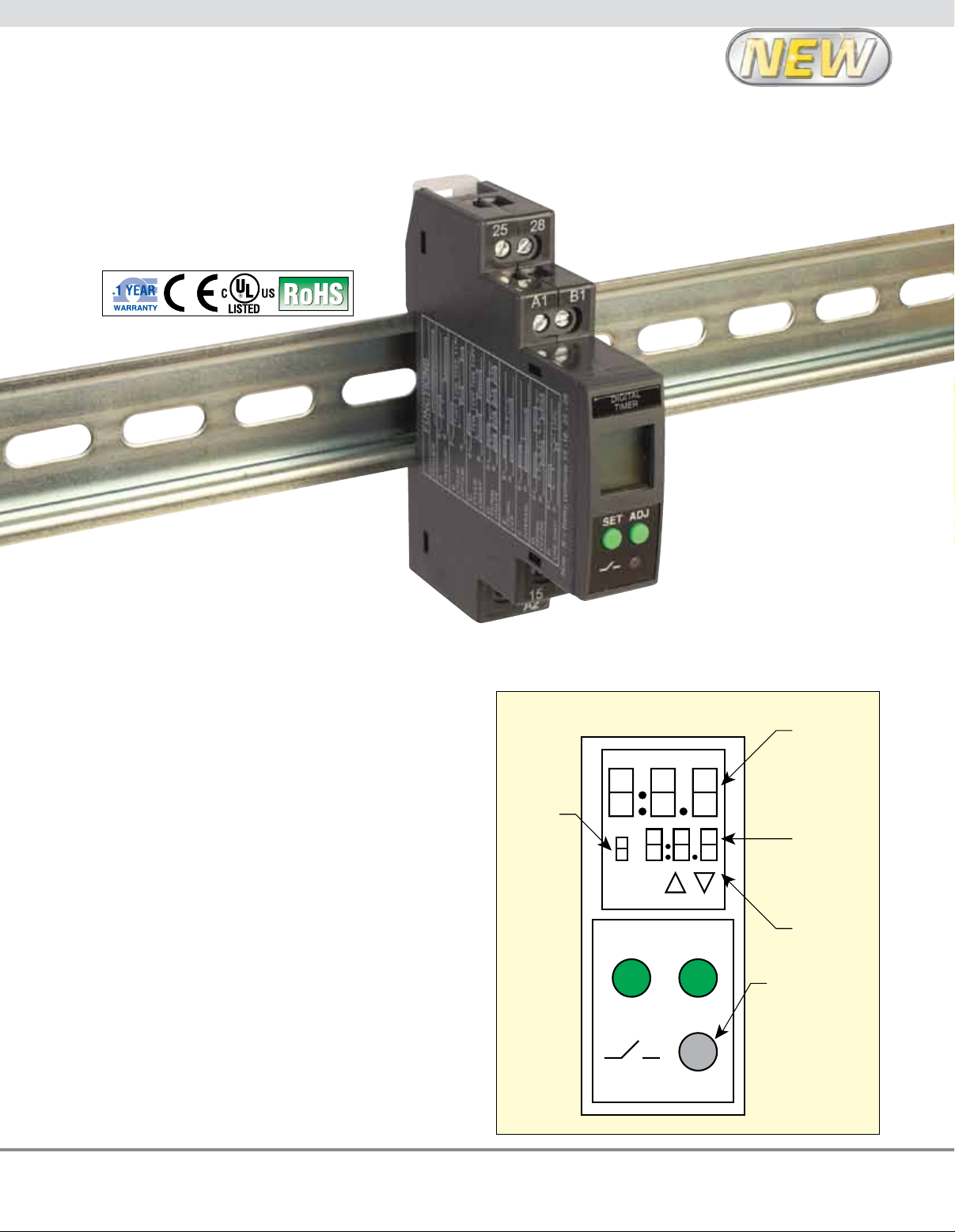
mode
HMS
SET
AU-AMT8-D2, DIN rail
mountable 8 function
digital timer. Shown
actual size.
Run
time
Preset
time
Up
down
ADJ
LED indication
for relay status
1
Page 2
SET
HMS
ADJ
Setting
mode
Run
time
Preset
time
Up
down
LED indication
for relay status
SET
HMS
ADJ
Setting
mode
Run
time
Preset
time
Up
down
LED indication
for relay status
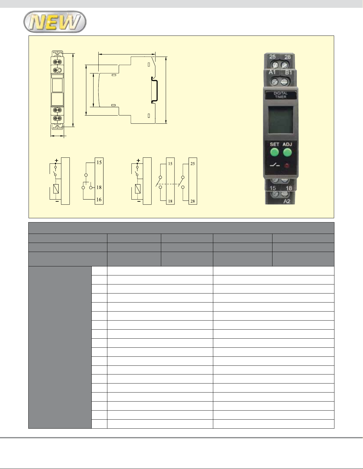
100 (3.34)
67 (2.64)
45 (1.8)
76.0 (2.99)
89 (3.5)
Dimensions: mm (inch)
76.0 (2.99)
45 (1.8)
67 (2.64)
100 (3.34)
17.5 (0.68)
Connection Diagrams
A1
24 to 240
Vac/Vdc
AU-AMT8-S1, AU-AMT12-S1
B1
A2
24 to 240
Vac/Vdc
A1
B1
A2
AU-AMT8-D2, AU-AMT12-D2
To Order
MODEL NO. AU-AMT8-S1 AU-AMT8-D2 AU-AMT12-S1 AU-AMT12-D2
OUTpUT CONTACTS NO/NC 2 NO NO/NC 2 NO
NUMBER OF TIMER
FUNCTIONS
FUNCTIONS/
SETTING MODES
1 ON Delay [A] ON Delay [0]
2 Cyclic OFF/ON [B] Cyclic OFF/ON [1]
3 Cyclic ON/Off [C] Cyclic ON/OFF [2]
4 Signal ON/OFF [D] Impulse on Energizing [3]
5 Signal OFF Delay [E] Accumlative Delay on Signal [4]
6 Interval [F] Accumlative Delay on Inverted Signal [5]
7 Signal OFF/ON [G] Accumlative Impulse on Signal [5]
8 One Shot Output [H] Signal ON Delay [7]
9 — Inverted Signal ON Delay [8]
10 — Signal OFF Delays [9]
11 — Impulse ON/OFF [A]
12 — Signal OFF/ON [B]
13 — Leading Edge Impulse 1 [C]
14 — Leading Edge Impulse 2 [D]
15 — Trailing edge Impulse 1 [E]
16 — Trailing Edge Impluse 2 [F]
17 — Delay Impulse [G]
18 — Inverted Signal ON Delay 2 [H]
8 8 18 18
89 (3.5)
shown actual size.
AU-AMT8-D2
2
 Loading...