

Page 1
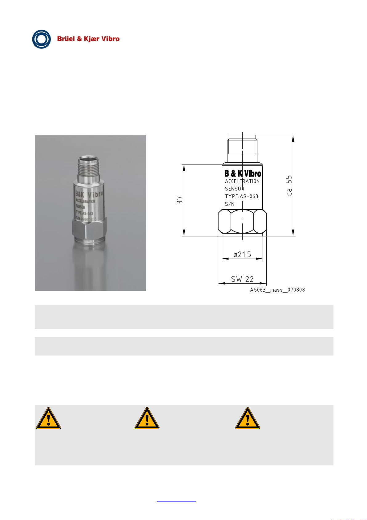
Abb. 1 Abmessungen
Fig. 1 Dimensions
Fig. 1 Dimensions
Mechanik
Mechanic
Mécanique
Masse
Weight
Masse
ca. 130 g (ohne Leitung)
approx. 130 g (without cable)
env. 130 g (sans câble)
Gehäusematerial
Housing material
Matériau du coffret
Edelstahl 1.4301
Stainless steel 1.4301
Acier spécial 1.4301
Anwendung
Application
Utilisation
063 wird vorzugsweise
rotierenden Maschinen, z.B. Turbinen,
compresseurs, etc.
respectées!
AS - 063
Beschleunigungs-Sensor mit Konstant-Stromversorgung
Acceleration Sensor with constant current power
Accéléromètre avec alimentation constante
Der Sensor ASzur Messung von Vibrationen an
Pumpen, Verdichtern usw. eingesetzt.
Beiliegende Sicherheitshinweise
für Installation, Inbetriebnahme
und Entsorgung müssen
berücksichtigt werden!
Brüel & Kjaer Vibro GmbH Tel. : +49 6151 428-1400 13.07.2017
Leydheckerstrasse 10 Fax : +49 6151 428-1401 C102 765.001 / V07
D-64293 Darmstadt E-Mail : [email protected] Seite/Page 1 von/of/de 6
The AS-063 is mainly used for
measurement of vibrations at rotating
machines such as turbines, pumps,
compressors, etc.
Attached safety instructions for
installation, commissioning and
disposal must be observed!
L'accéléromètre AS-063 est utilisé de
préférence pour mesurer les
vibrations sur des machines rotatives,
telles que turbines, pompes,
Les instructions de sécurité
jointes concernant l'installation, la
mise en route, et la dépose,
doivent être strictement
Page 2
AS – 063
Seite/Page 2 von/of/de 6
© Brüel & Kjaer Vibro / C102 765.001 / V07 / 13.07.2017
Technische Änderungen vorbehalten!
Spécifications techniques sous réserve de modifications!
Messprinzip
Measuring Principle
Principe de mesure
arbeiteten nach dem piezoelektrischen
Kompressionsprinzip. Im Sensor bilden
Masse-Dämpfungssystem.
the sensor.
Les accéléromètres fonctionnent selon
céramique et
une masse interne forment un système
d'amortissement à ressort-masse.
ch elektrische
Beschleunigung sind.
If this system is subjected to vibrations
force on the piezo element. As a result
l to
Lorsque des vibrations agissent sur ce
l'accélération.
ntegrierter Verstärker wandelt das
Spannungssignal um.
signal.
tension utilisable.
Lieferumfang
Delivery extend
Étendue de la fourniture
• Sensor AS-063
• Sensor AS-063
• Sensor AS-063
• Gewindestift M8 x 14
• Threaded stud M8 x 14
• Goujon filetée M8 x 14
• Gewindestift M8 x 1/4" 28 UNF
• Threaded stud M8 x 1/4" 28 UNF
• Goujon filetée M8 x 1/4" 28 UNF
• Dokumentation
• Documentation
• Documentation
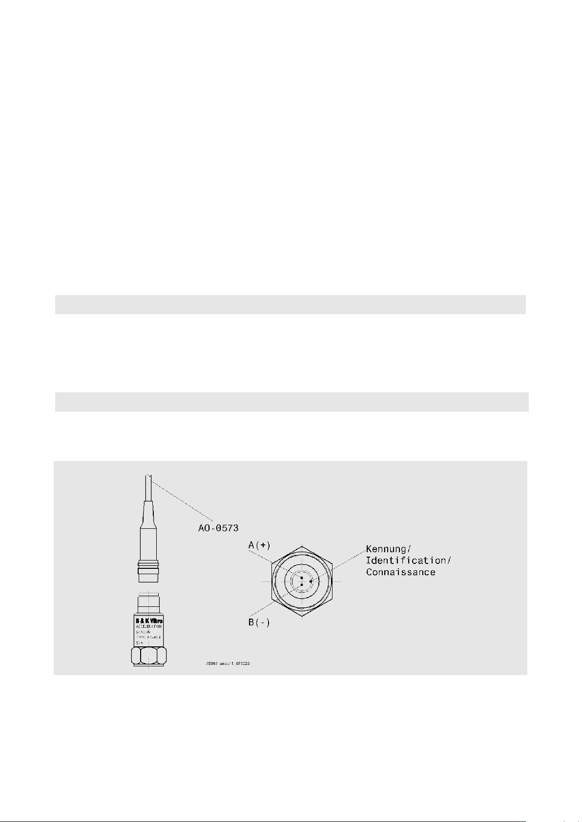
Anschluss
Connection
Raccordement
assignment:
B = - (0V / GND)
B = - (0V / GND)
B = - (0V / GND)
Abb. 3
Fig. 3
AS-063
Fig. 3
Die Beschleunigungs-Sensoren
eine Piezo-Keramikscheibe und eine
interne Sensormasse ein Feder-
Werden in dieses System
Schwingungen eingeleitet, übt die
Masse eine Wechselkraft auf das
Piezoelement aus. Infolge des PiezoEffektes entstehen dadur
Ladungen, die proportional zur
Ein i
Ladungssignal in ein nutzbares
The acceleration sensor operates
according to the piezo-electric
compression principle. A piezoceramic disc and an internal sensor
mass form a spring-mass system in
the mass produces an alternating
of the piezo effect this produces an
electrical charge that is proportiona
vibration acceleration.
An integrated amplifier converts this
charge signal into a usable voltage
le principe piézoélectrique de
compression. A l'intérieur de l'accéléromètre, un disque piézo-
système, la masse exerce une force
alternante sur L'élément
piézoélectrique . Dû à l'effet piézoélectrique, ceci provoque des charges
électriques proportionnelles à
Un amplificateur intégré transforme le
signal de charge en un signal de
Steckverbindung (MIL C-5015) Connector (MIL C-5015)
A = + (SIG/4mA)
A = + (SIG/4mA)
Steckeranschluss AS-063
Connector assignment
Connecteur (MIL C-5015)
A = + (SIG/4mA)
Raccordement AS-063
Technical specifications subject to change!
Page 3

AS – 063
© Brüel & Kjaer Vibro / C102 765.001 / V08 / 13.07.2017
Seite/Page 3 von/of/de 6
Technische Änderungen vorbehalten!
Spécifications techniques sous réserve de modifications!
Anschlussleitung
Connecting cable
Conducteur de raccordemen
AO-0573-S-xxxx
AO-0573-S-xxxx
AO-0573-S-xxxx
xxxx = Länge
xxxx = Length
xxxx = Longeur
xxxx = 0200 = 20,0m
Konstant-Stromversorgung IB
Constant Power supply IB
Alimentation constante IB
verpolungsfest bis
polarised untill
polarité fixe à
Versorgungsspannung UB
Voltage supply UB
Tension d'alimentation UB
Min.+18 VDC/ Max.+30 VDC
Min.+ 18 VDC/ Max.+30 VDC
Min.+18 VDC/ Max.+30 VDC
Montage
Mounting
Montage
Ankopplung
Coupling
Couplage
Grundsätzlich gilt:
General rule:
Principe appliqué :
Messobjektes, an die er montiert ist.
laquelle il est raccordé.
Sensor ist eine
it is too large.
Messungen bei hohen Frequenzen.
pour les mesures à haute fréquence.
The sensor is to be attached using the
la fourniture.
Wahlweise mit:
Selectable with:
Au choix avec :
• Gewindestift M8 x 14 oder
• Threaded stud M8 x 14 or
• goujon fileté M8 x 14 ou
UNF
beliebig.
xxxx = 0030 = 3,0m
xxxx = 0050 = 5,0m
4 mA
Min. 2 mA / Max. 10 mA),
+24 V
Die Masse des BeschleunigungsSensors sollte wenigstens zehnmal
kleiner sein als die schwingungstechnisch relevante Masse des
Der BeschleunigungsZusatzmasse, welche das
Messobjekt belastet und dessen
Schwingverhalten ändert.
xxxx = 0100 = 10,0m
xxxx = 0150 = 15,0m
4 mA
Min. 2 mA / Max. 10 mA
+24 V
The weight of the acceleration sensor
should always be lower at least by a
factor ten than the weight of the object
onto which it is mounted.
The acceleration sensor is an
additional parasitic mass which loads
the object on which it is mounted and
this changes the vibration behaviour if
xxxx = 0250 = 25,0m
xxxx = 0500 = 50,0m
4 mA
Min. 2 mA / Max. 10 mA
+24 V
La masse de l'accéléromètre doit être
au moins dix fois plus petite que la
masse significative pour la technique
vibratoire de l'objet à mesurer, à
L'accéléromètre est une masse
supplémentaire qui sollicite l'objet à
mesurer et qui modifie son comportement vibratoire.
Der Sensor benötigt eine
kraftschlüssige, kontaktresonanzfreie und steife Befestigung am
Messobjekt, insbesondere für
Der Sensor ist mit dem beigefügten
Gewindestift zu montieren.
• Gewindestift M8 / 1/4“ 28 UNF
Die Einbaulage an der Maschine ist
The sensor requires a friction-locked,
contact resonance-free, rigid mounting
to the object, particularly for
measurements at high frequencies.
supplied threaded stud, either:
• Threaded stud M8 / 1/4“ 28
Can be mounted in any position . La position de montage est facultative.
La fixation de l'accéléromètre sur
l'objet mesuré doit être rigide, réalisée
par adhérence et sans résonance
provoquée par contact, en particulier
L'accéléromètre doit être monté à
l'aide du goujon fileté faisant partie de
• goujon fileté M8 / 1/4“ 28 UNF
Technical specifications subject to change!
Page 4
AS – 063
Seite/Page 4 von/of/de 6
© Brüel & Kjaer Vibro / C102 765.001 / V07 / 13.07.2017
Technische Änderungen vorbehalten!
Spécifications techniques sous réserve de modifications!
90°
15
M8
12
5
ø28
>
0,8
**
*
max. Einschraubti efe
max. reach of screw
Profondeur de vissage maxi
Gewindestift mit LOCTITE gesichert
Threaded stud secured wit h LOCTITE
Goupill e fi letée sécuri sée au LOCTITE
Beschleuni gungs-Sensor
Acceleration Sensor
Accéléromètre
AS-063
Montagefläche
Mounting surface
Surface de montage
AS063-4def (060119)
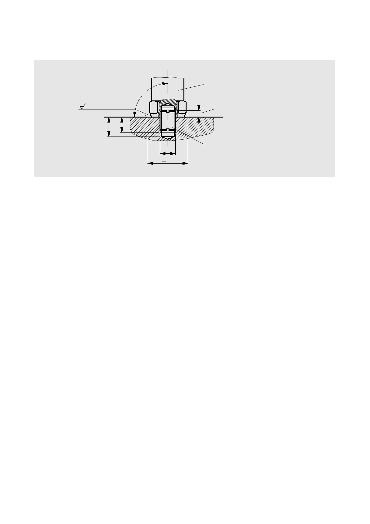
Abb. 4 Montage
Fig. 4 Mounting
Fig. 4 Montage
bearbeitet sein (Rautiefe 0.8) und
28 mm haben.
diamêtre de 28mm.
werden - plane Auflagefläche!
ust be deburred
– flat mounting surface!”
la surface de montage plane !
inschrauben und
270 high strength
dans la surface de montage, puis
résistance.
résonances par contact.
stifts 12 mm.
threaded stud 12 mm.
vissage de 12 mm.
≤ 5 mm!
sensor ≤ 5 mm!
capteur ≤ 5 mm!
fourniture : 3,5 Nm.
• Die Montagefläche muss im
Bereich des Sensors plan
einen Mindestdurchmesser von
• Montagefläche mit Gewinde-
bohrung M8 x 1,25 bzw.
1/4“ 28 UNF, 15 mm tief
versehen.
• Die Bohrung muss entgratet
• Gewindestift gemäß Abb. 4 in
Montagefläche e
sichern (z.B. LOCTITE 243
mittelfest, LOCTITE 270
hochfest).
• Dünne Schicht Silikonfett auf die
Montagefläche auftragen, um
Kontaktresonanz zu verringern.
• The mounting surface in the area
of the sensor must be machined
flat (Mounting surface 0.8) and a
minimum diameter of 28mm.
• Provide a size M8 x 1.25 ,resp.
1/4“ 28 UNF threaded hole 15
mm deep in the surface of the
machine.
• “The drilled hole m
• Screw the threaded stud into the
mounting surface in accordance
with Fig. 4 and secure it with
adhesive, e.g. LOCTITE 243
medium strength, or LOCTITE
• Apply a thin film of silicone grease
on the mounting surface to
prevent contact resonance.
• Dans les environs de l'accéléro-
mètre, la surface de montage
doit être usinée plane (Surface
de montage 0.8)et havé un
• Réaliser un taraudage M8 x 1,25
ou bien 1/4“ 28 UNF, 15 mm de
profondeur, dans la surface de
montage.
• Le trou fraisé doit être ébavuré et
• Visser le goujon fileté selon fig. 4
le bloquer avec, par exemple,
LOCTITE 243 à résistance
moyenne, LOCTITE 270 à haute
• Appliquer une fine couche de
graisse de silicone sur la surface
de montage, afin de réduire les
• Einschraubtiefe des Gewinde-
• Sensor auf Gewindestift auf-
schrauben
• Max. Einschraubtiefe des Sensors
• Anzugsmoment für beigefügten
Gewindestift:3,5 Nm.
• Maintain a max. length of the
• Screw the sensor onto the
threaded stud.
• Maintain a max. length of the
• Torque for the supplied threaded
stud is 3,5 Nm.
Technical specifications subject to change!
• Respecter la profondeur maxi. de
• Visser l'accéléromètre sur le
goujon fileté.
• Respecter la profondeur maxi. de
• Couple de serrage pour le goujon
fileté faisant partie de la
Page 5
AS – 063
© Brüel & Kjaer Vibro / C102 765.001 / V08 / 13.07.2017
Seite/Page 5 von/of/de 6
Technische Änderungen vorbehalten!
Spécifications techniques sous réserve de modifications!
Technische Daten
Technical Data
Données Techniques
Elektrik
Electrical
Élém. élect.
Empfindlichkeit (80 Hz /23±3 °C)
Sensitivity (at 80 Hz /23±3 °C)
Sensibilité (á 80 Hz /23±3 °C)
10,2 mV/m/s2 ± 5 %
10,2 mV/m/s2 ± 5 %
10,2 mV/m/s2 ± 5 %
Genauigkeit der Empfindlichkeit
Accuracy of Sensitivity
Précision de Sensibilité
-50 °C ... +120 °C : ± 5 %
-50 °C ... +120 °C : ± 5 %
-50 °C ... +120 °C : ± 5 %
Richtungsfaktor (80 Hz)
Transverse sensitivity (80 Hz)
Facteur transverse (80 Hz)
≤ 8 ... 10 %
≤ 8 ... 10 %
≤ 8 ... 10 %
Resonanzfrequenz
Resonance frequency
Fréquence propre
35kHz ± 3 kHz
35kHz ± 3 kHz
35kHz ± 3 kHz
AS-063 100 mV/g
S/N 00002045
-30
-20
-10
0
10
20
30
1 10
100 1000
10000 100000
Frequenz / Hz
Frequenzgang / dB
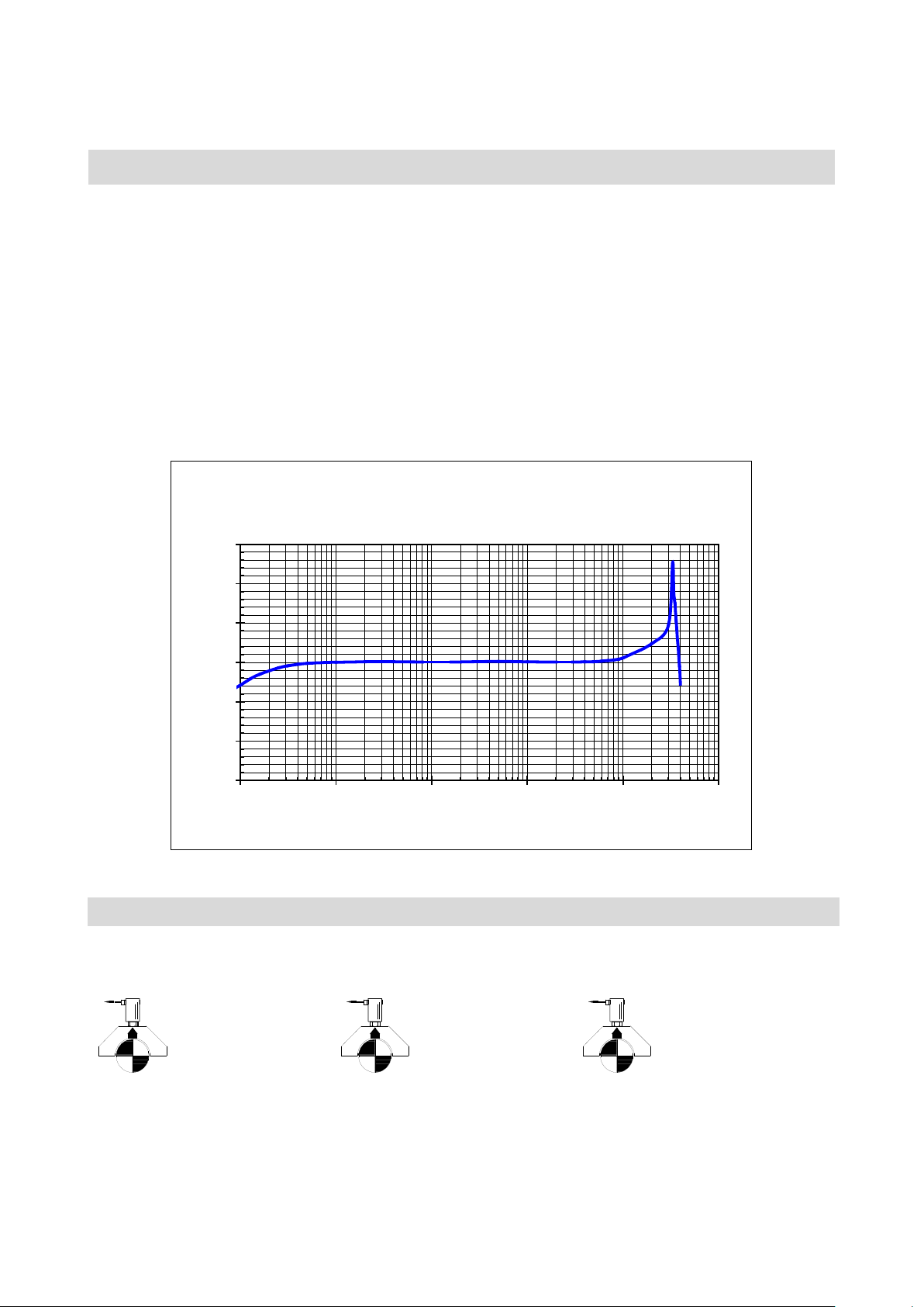
Abb. 2
der Empfindlichkeit
Fig. 2
of sensitivity
Fig. 2
facteur de transmission
Messbereich
Measuring range
Plage de mesure
± 20 g (UB = +18 V) : ±7%
± 20 g (UB = +18 V) : ±7%
± 20 g (UB = +18 V) : ±7%
VSB01
richtung der Lagerschale entsteht ein
VSB01
VSB01
ssous, il se produit un signal
positif.
100 mV/g ± 5 %
4 Hz ... 10 kHz : ± 5 %
1,5 Hz / 13 kHz : ±3 dB
100 mV/g ± 5 %
4 Hz ... 10 kHz : ± 5 %
1,5 Hz / 13 kHz : ±3 dB
100 mV/g ± 5 %
4 Hz ... 10 kHz : ± 5 %
1,5 Hz / 13k Hz : ±3 dB
Typischer Frequenzgang
± 80 g (UB = +24 V...+30 V) : ±7%
± 40 g (U
Bei der eingezeichneten Bewegungs-
positives Signal.
= +20 V) : ±7%
B
Polarität
Typical frequency response
± 80 g (UB = +24 V...+30 V) : ±7%
± 40 g (U
= +20 V) : ±7%
B
± 80 g (UB = +24 V...+30 V) : ±7%
± 40 g (U
Polarity
A movement of the bearing housing
in the direction shown below
produces a positive signal.
Technical specifications subject to change!
Lorsque la coquille de coussinet se
déplace dans le sens indiqué sur le
croquis ci-de
Courbe en réáponse type du
= +20 V) : ±7%
B
Polarité
Page 6

AS – 063
Seite/Page 6 von/of/de 6
© Brüel & Kjaer Vibro / C102 765.001 / V07 / 13.07.2017
Technische Änderungen vorbehalten!
Spécifications techniques sous réserve de modifications!
des Ausgangs
output
sortie
(Aussteuerung 1 V
eff
IB = 4 mA)
(Level control 1 V
eff
IB = 4 mA)
(modulation 1 V
eff
IB = 4 mA)
(- 50°C ... +125 °C)
(- 50 °C ... +125 °C)
(- 50 °C ... +125 °C)
+12,5 V ±1,5 V
+12,5 V ±1,5 V
+12,5 V ±1,5 V
Dehnungsempfindlichkeit
Strain sensitivity
Sensibilité à la déformation
< 0,002 g/ ( µm/m )
< 0,002 g/ ( µm/m )
< 0,002 g/ ( µm/m )
Magnetfeldempfindlichkeit
Magnetic field sensitivity
Sensibilité au champ magnétique
< 1 kHz: 0,014 g/mT
< 1 kHz: 0,014 g/mT
< 1 kHz: 0,014 g/mT
(Gehäuse - Pin A/B)
(Housing - Pin A/B)
(Boîtier - Pin A/B)
≥ 20 MΩ
≥ 20 MΩ
≥ 20 MΩ
Arbeitstemperaturbereich
Operating temperature range
Plage de température de travail
- 55 °C ... + 125 °C
- 55 °C ... + 125 °C
- 55 °C ... + 125 °C
d´origine)
-20 °C ... +70 °C
-20 °C ... +70 °C
-20 °C ... +70 °C
Schutzart DIN 60529
Protection class DIN 60529
Protection DIN 60529
IP 66/67
IP 66/67
IP 66/67
Überlastbarkeit
Overload capacity
Surcharge
(alle Richtungen)
(all directions)
(toutes directions)
EMV
EMC
CEM
EN 61326-1
EN 61326-1
EN 61326-1
kommen.
3) influences on
Bei Störeinflüssen dieser Art wird ein
nfluences of this
type a grounded protective conduit is
est recommandé d’installer un flexible de
pour la ligne du capteur.
WEEE-Reg.-Nr. DE 69572330
WEEE-Reg.-No. DE 69572330
WEEE-Reg.-N°. E 69572330
Anwendungsbereich: 9
application area: 9
domaine d'application: 9
Dynamischer Innenwiderstand
≤ 300 Ω (Arbeitsfrequenzbereich)
ca. 2 kΩ (Resonanzfrequenz)
Ruhepotential
< 80 Hz: 0,001 g/mT
Isolationswiderstand
Lagerungstemperaturbereich (in
Originalverpackung)
Dynamic internal resistance of
≤ 300 Ω (Operating frequency range)
approx. 2 kΩ (Resonance frequency)
Open-circ. pot.
< 80 Hz: 0,001 g/mT
Insulation resistance
Storage temperature range (in
original packaging)
Résistance interne dynamique de la
≤ 300 Ω (gamme des fréq. de travail)
ca. 2 kΩ (fréquence de résonance)
Potentiel de repos
< 80 Hz: 0,001 g/mT
Résistance diélectrique
Plage de température pour le
stockage (dans l´embalage
dauernd 500 g
Schock 5000 g
Durch elektromagnetische Einstreuungen (nach EN 61000-4-3) kann es
zu Beeinflussungen des Messwertes
geerdeter Stahlschutzschlauch für
die Sensorleitung empfohlen.
Produktkategorie /
continuous 500 g
shock 5000 g
Through electro-magnetic stray fields
(acc. to EN 61000-4the measured values may arise.
In case of disturbing i
recommended for the signal cable.
product category /
permanente 500 g (crête)
par choc 5000 g
Les interférences électromagnétiques
(selon la norme EN 61000-4-3) peuvent
altérer la valeur mesurée.
En cas de perturbations de ce genre, il
protection métallique raccordé à la terre
catégorie de produits /
Technical specifications subject to change!
Page 7
 Loading...