

Page 1

AN0007
Issue 1.2
09/04/2025
Change Note 805
Page 1 of 14
ARDUINO to PLATINUM COMMS
HELP DOCUMENT
Dynament Limited
Hermitage Lane Industrial Estate ٠ Kings Mill Way ٠ Mansfield ٠ Nottinghamshire ٠ NG18 5ER ٠ UK.
Tel: 44 (0)1623 663636
Application Note
AN0007
Page 2

AN0007
Issue 1.2
09/04/2025
Change Note 805
Page 2 of 14
Contents
Dynament Limited ................................................................................................................... 1
Connecting the Sensor ........................................................................................................... 3
Arduino IDE .............................................................................................................................. 5
Code Explanation .................................................................................................................... 9
Packet Breakdown ................................................................................................................ 11
Using Serial.read() ................................................................................................................ 13
Advanced Conversion Notes ........................................................................................... 14
Page 3
AN0007
Issue 1.2
09/04/2025
Change Note 805
Page 3 of 14
Connecting the Sensor
This data sheet uses the Arduino Mega as an example. The Ardunio Mega provides
more than one comm port, therefore comm port 1 is used to communicate with the
sensor and comm port 0 is used to print to the PC.
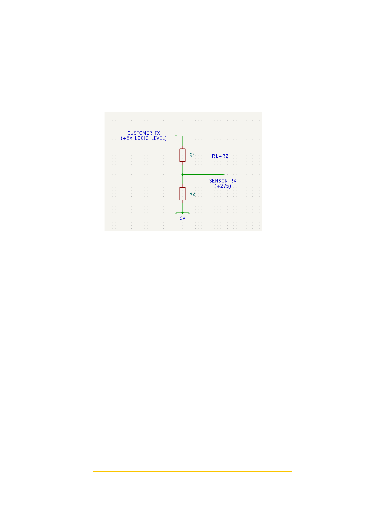
The Arduino uses 5v logic high whereas the Platinum Sensor uses 3.3v, so to
prevent damage to the Sensor a voltage divider must be used. Suggested values for
R1 and R2 are 4K7Ω.
Figure 1: Lowers the voltage to useable level
The Sensor transmit line going to the Arduino receive doesn’t need a divider as 3.3v
is an acceptable input to the Arduino.
In order to power the Sensor it must be connected to 5v and 0v. To do this you can
use the pins on the Arduino.
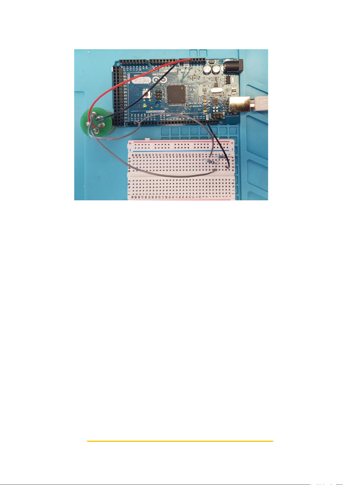
After this is complete, the sensor should now have the following pins connected:
5v -> 5v Arduino pin
0v -> Arduino GND
Tx -> Arduino RX1
Rx -> Goes to the output of the potential divider. The input goes to Arduino Tx
Page 4
AN0007
Issue 1.2
09/04/2025
Change Note 805
Page 4 of 14
After this is complete your Platinum Sensor should be connected as shown:
Figure 2: Sensor is shown upside down with a solder adapter
If you are using an Arduino with only one comm port (like the Arduino Uno) you will
have to connect it to that, however when you use the serial monitor (shown later) it
will also show the hex that is transmitted.
Page 5
AN0007
Issue 1.2
09/04/2025
Change Note 805
Page 5 of 14
Arduino IDE
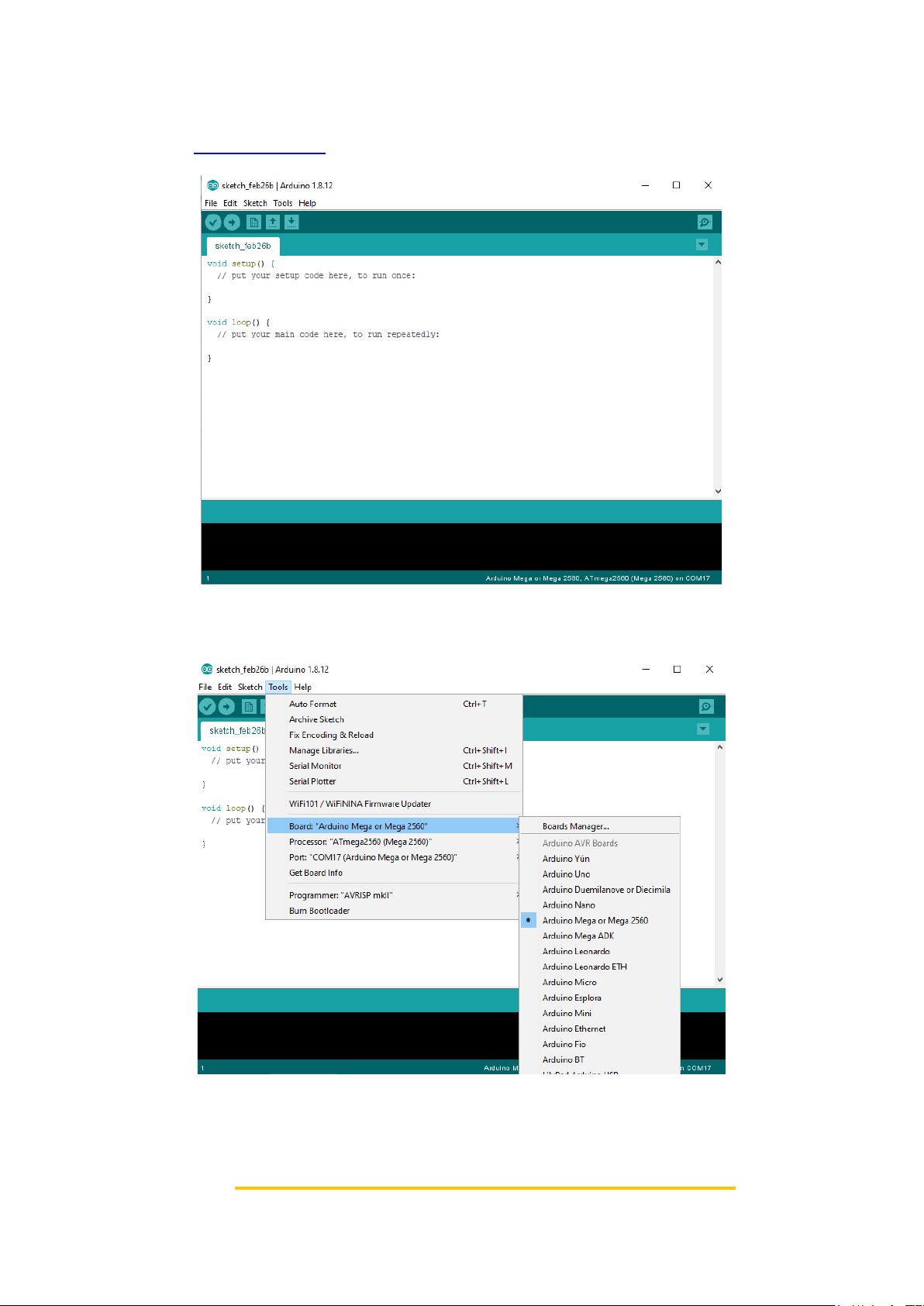
Go to the Arduino website and download the newest version of the Arduino IDE
software. Once installed you should see the following screen:
Figure 3: Arduino home screen
In the tools drop down menu select the Arduino board, processor and port you are
using:
Figure 4: Select Board, Processor and Port options
Page 6

AN0007
Issue 1.2
09/04/2025
Change Note 805
Page 6 of 14
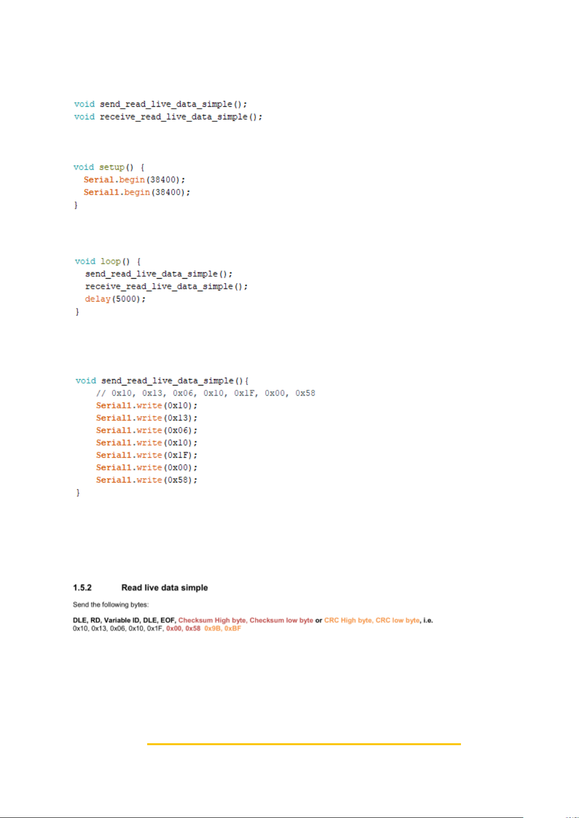
Copy in this example code:
void send_read_live_data_simple();
void receive_read_live_data_simple();
void setup() {
Serial.begin(38400);
Serial1.begin(38400);
}
void loop() {
send_read_live_data_simple();
receive_read_live_data_simple();
delay(5000);
}
void send_read_live_data_simple(){
// 0x10, 0x13, 0x06, 0x10, 0x1F, 0x00, 0x58
Serial1.write(0x10);
Serial1.write(0x13);
Serial1.write(0x06);
Serial1.write(0x10);
Serial1.write(0x1F);
Serial1.write(0x00);
Serial1.write(0x58);
}
void receive_read_live_data_simple(){
while (Serial1.available())
{
Serial.print(Serial1.read(), HEX);
Serial.print("|");
}
Serial.println();
}
Page 7
AN0007
Issue 1.2
09/04/2025
Change Note 805
Page 7 of 14
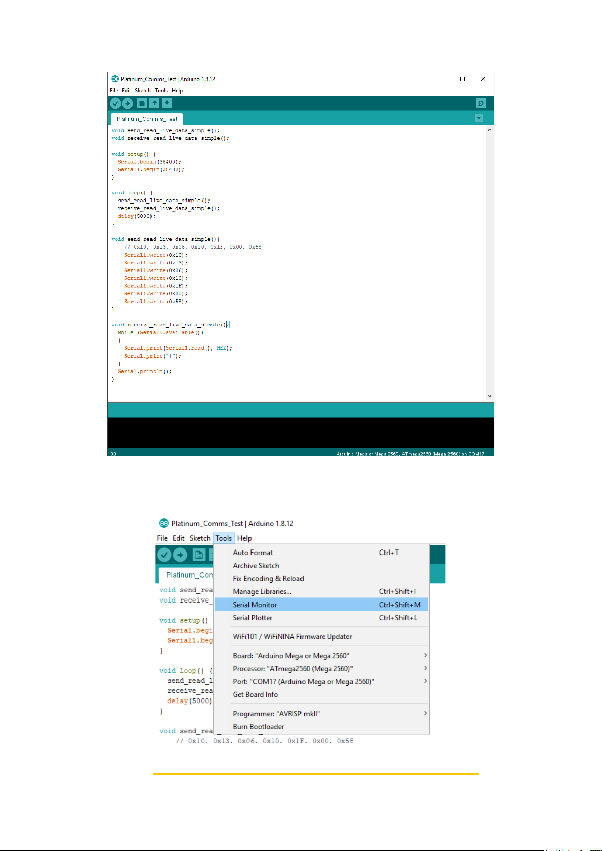
Figure 5: Code ready to upload
Click the arrow to upload the code to the Arduino.
After the Arduino has been programmed open the serial monitor.
Figure 6: Open the Serial Monitor
Page 8
AN0007
Issue 1.2
09/04/2025
Change Note 805
Page 8 of 14
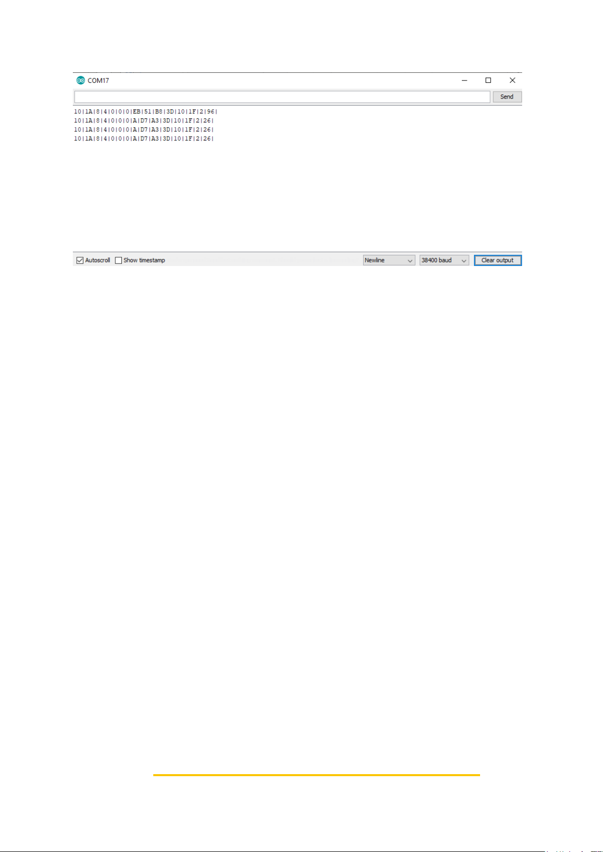
Figure 7: The Serial Montor shows the packet that has been received
Page 9
AN0007
Issue 1.2
09/04/2025
Change Note 805
Page 9 of 14
Code Explanation
The Arduino IDE uses C++ to program the Arduino.
This line is a forward declaration. This is used to tell the Microcontroller that further
down in the program the ‘send_read_live_data_simple’ function and the
‘receive_read_live_data_simple’ function will be called.
Next is the setup function. This code gets run only once on startup. It starts the
Serial0 and Serial1 ports. Serial0 is what is shown in the serial monitor screen.
Serial1 is the port to communicate with the sensor.
This is the main loop, this code gets repeatedly looped. You can see by reading the
function names that it sends a request to read a simplified version of the live data
struct. Then it reads the receive port to read the reply. After this the Microcontroller
waits 5000mS.
This function writes the request to get the live data simple struct to serial port 1. As
previously mentioned if you only have one serial port you should change Serial1 to
Serial.
To see the full list of commands, refer to the Premier sensor Communications
protocol document. Here is the part of the document that tells you what to write for
this command:
Page 10
AN0007
Issue 1.2
09/04/2025
Change Note 805
Page 10 of 14
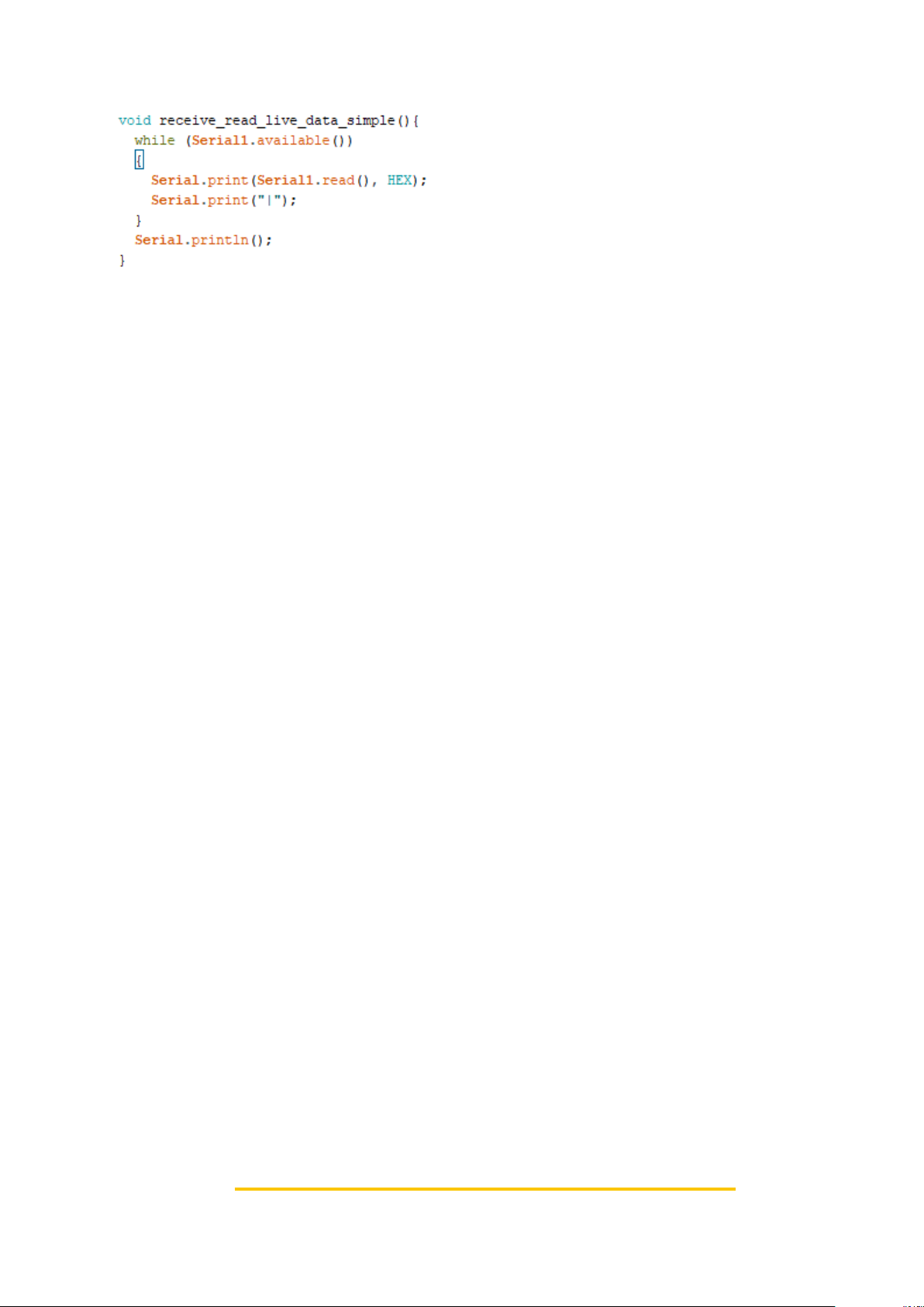
This function loops the read function while there is still data to be received from the
Platinum Sensor. Serial1.read() reads the data from Serial1 which is connected to
the sensor and prints it on Serial0 so it can be seen on the serial monitor. The
character ‘|’ is then printed to break up each byte that is received to make it clearer
on the serial monitor.
After this is complete it writes a new line to the serial monitor.
Page 11
AN0007
Issue 1.2
09/04/2025
Change Note 805
Page 11 of 14
Packet Breakdown
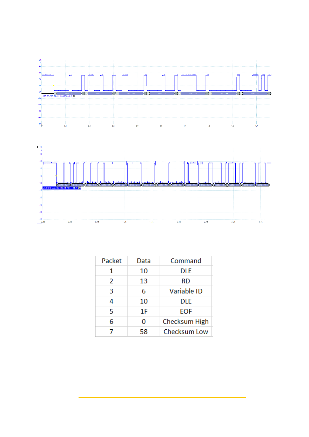
Figure 8 and 9 show the output of a serial decoder connected to the receive and
transmit lines.
Figure 8: Outgoing Packet
Figure 9: Incoming Packet
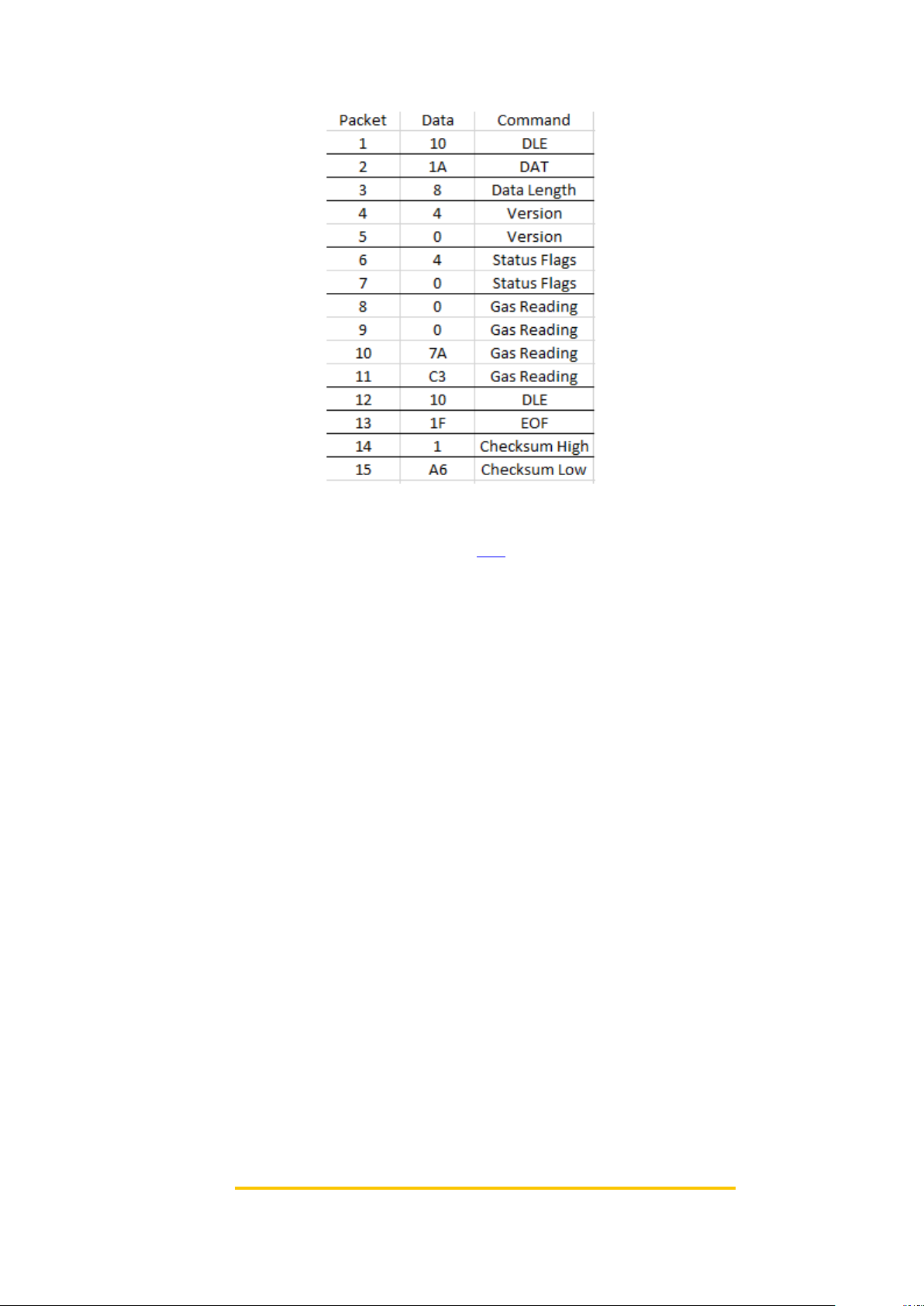
Figure 10 and 11 show the outgoing and incoming hex respectively with a column
that shows which command it is.
Figure 10: Outgoing Packet Description
Page 12
AN0007
Issue 1.2
09/04/2025
Change Note 805
Page 12 of 14
Figure 11: Incoming Packet Description
Please note the Gas reading is a decimal not an integer. This decimal is in IEEE-754
format, you can use an online converter like this to convert it. The gas value in this
case shows -250 (as it was in error mode at the time).
Page 13
AN0007
Issue 1.2
09/04/2025
Change Note 805
Page 13 of 14
Using Serial.read()
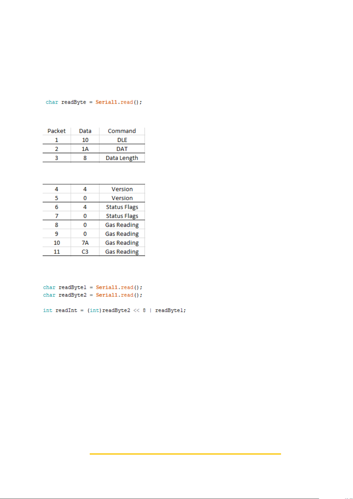
The previous code only printed the data received to the serial monitor, if you want to save the data in
variables you will need to do some further processing. The packet you receive is split into bytes,
because of this you will need to concatenate some of this data into variables.
Serial1.Read() returns an int (which for Arduino is 16 bits), however, only the first 8 bits are used.
Because of this we can copy it into a smaller data type that is only 8 bits, in this case I will use char.
for the packets that are only a byte long, this works fine:
For the packets that are 2 bytes or 4 bytes long you will need to concatenate the data.
You can do this in a lot of different ways, here what I am going to do is left shift the data and then OR
it.
Using this code, if readByte1 is 0x34 and readByte2 is 0x12.
(int)readByte2 // this converts the 0x12 into 0x0012.
(int)readByte2 << 8 // this shifts the bits over by a byte making it 0x1200.
(int)readByte2 << 8 | readByte1 // this then gets OR’ed, with 0x34 making 0x1234.
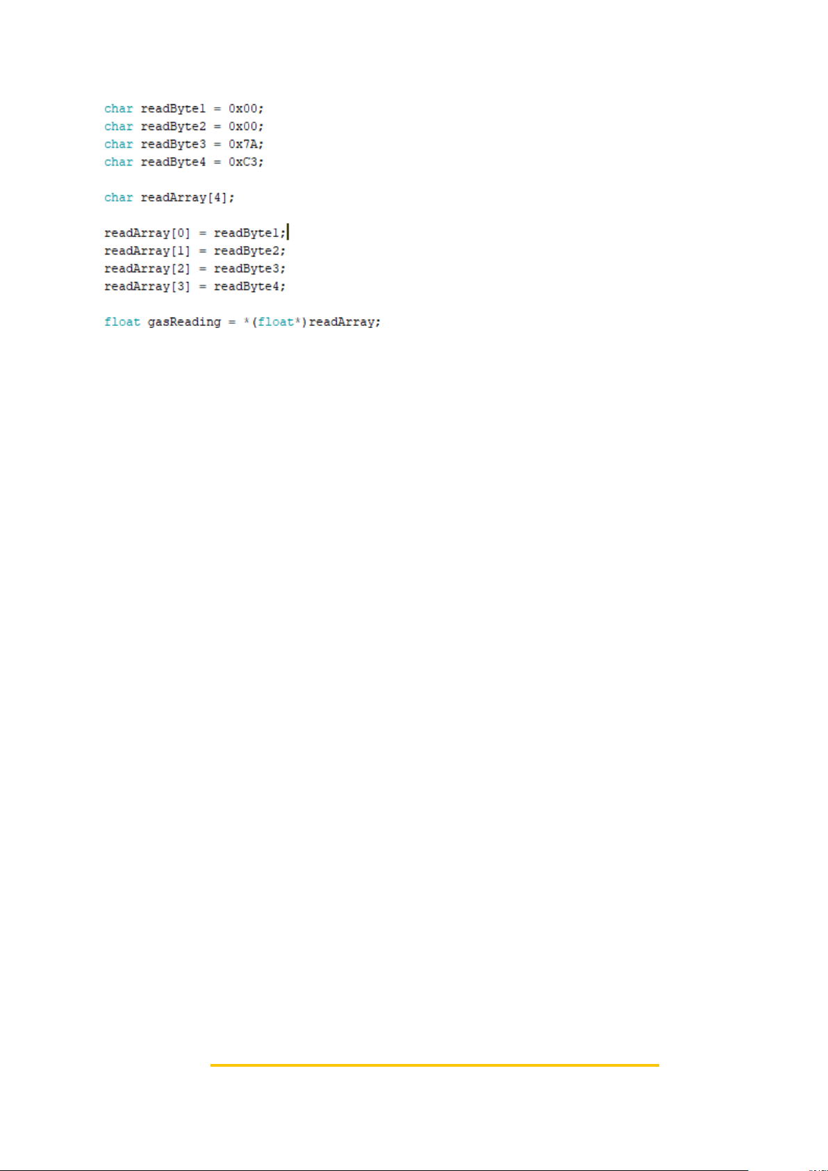
Another way to do this would be to put the values into an array and then convert the array into the
type you want:
Page 14
AN0007
Issue 1.2
09/04/2025
Change Note 805
Page 14 of 14
chars are a byte long, whereas float is 4 bytes long. Because of this if we make an array of 4 chars
with our values in it and change the type to float.
In this case readArray is a pointer to a char array. (float*)readArray this part casts it to a pointer to a
float and then a * is added to the front to get the value of the float.
Advanced Conversion Notes
1. Serial.read() returns int instead of char because errors will return negative values. Your
program should check for this.
2. uint8_t and uint16_t should be used in place of char and int respectively, as these types do
not have a standard size (on my PC int is 32 bits whereas on the Arduino it is 16 bits).
3. The comms protocol contains byte stuffed characters (also known as control characters), this
is explained in more detail in the tds0045 Premier sensor Communications protocol
document. Because of this the read live data simple packet will occasionally be bigger than
expected.
 Loading...