

Page 1
PWR COM B[+] A[-]
Bulletin AQ-CDTA-QS-2
TO
SUPPLY
NEXT
PWR COM B[+] A[-]
[1
1-3/32 [27.69]
®
Series CDTA and CDTC Communicating Carbon Dioxide Detector
Specications - Installation and Operating Instructions
2-51/64 [71.12]
4-1/2
14.30]
The Series CDTA and CDTC Communicating Carbon Dioxide Detector combines
the function of several room sensors into a single, compact housing. Both the
Series CDTA and the CDTC’s parameters include carbon dioxide, temperature, and
temperature set point with override while the CDTA also includes a humidity sensor.
By having eld selectable Modbus® and BACnet Communications, only four wires are
needed for power and the communication signal. The communicating detectors can be
daisy chained together to further reduce installation cost. In order to reduce the set up
time, the RS-485 MAC address is set up using on-board DIP switches. A second set
of DIP switches are used to select whether output is Modbus® RTU or BACnet MS/TP
communication protocols and to limit access to the set up menu.
The barometric pressure can be programmed to correct for altitude. The humidity
parameter in the Series CDTA uses a capacitive polymer sensor and the temperature
is measured using a 10KΩ thermistor sensor.
Optional integral display is available to display any of the parameters. For applications
in which the building occupants aren’t familiar with CO2 concentrations, the LCD can be
programmed to display temperature, humidity (only for Series CDTA), or temperature
set point instead. For environments occupied 24 hours per day it is recommended to
periodically expose the CO2 sensor to outside ambient air.
The Series CDTA and CDTC CO2 transmitters are maintenance free instruments with
the ability to adjust the CO2 calibration by using the on-board Automatic Background
Calibration (ABC) logic for intermittently occupied spaces. The ABC algorithm accounts
for long term drift by making small adjustments to it’s zero calibration point based on
the lowest CO2 readings it measures eight day cycles.
INSTALLATION
WARNING
national and local electrical codes. Use copper conductors only.
Avoid locations where severe shock or vibration, excessive
NOTICE
NOTICE
MOUNTING
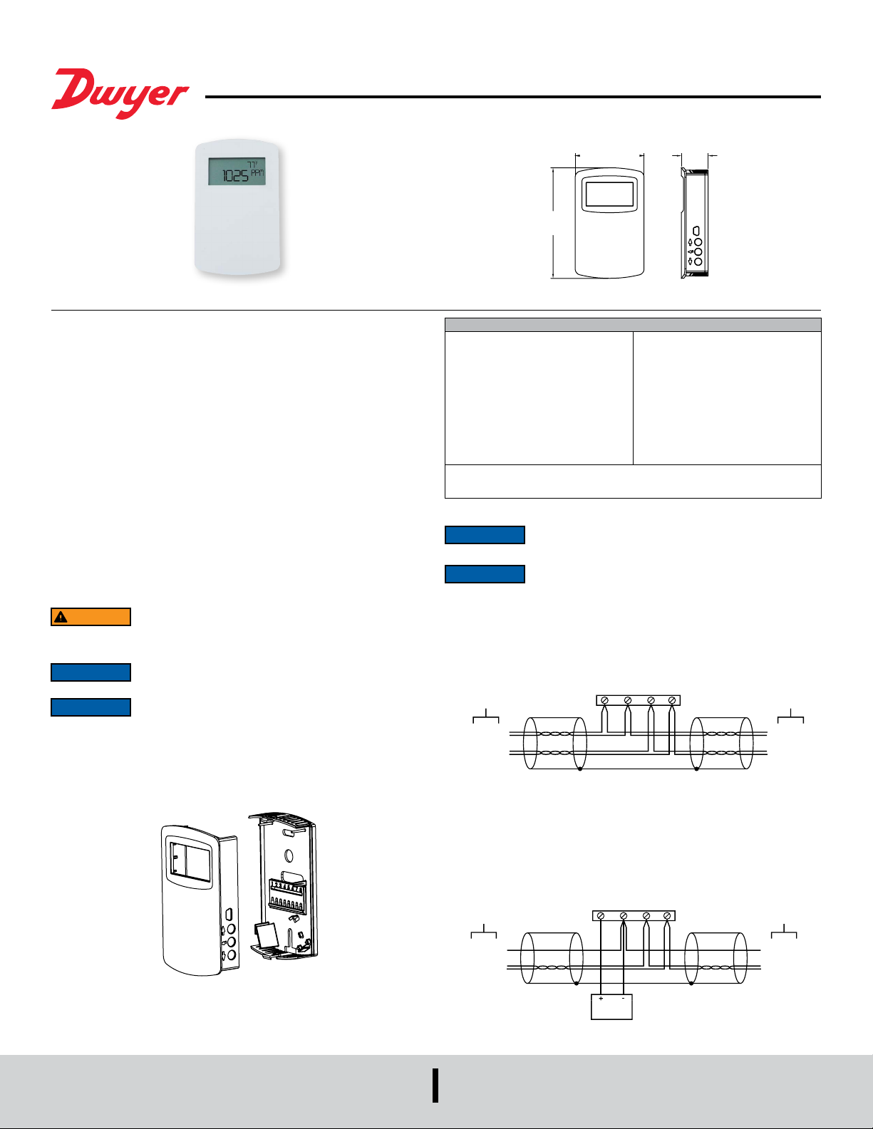
1. Push tab on top and bottom of cover and lift cover from back plate (See Figure 1).
2. Select the mounting location, away from diffusers, lights or any external inuences.
3. Mount transmitter on a vertical surface to a standard electrical box using the two #6
M2C type screws provided.
4. Pull wires through sub base hole and make necessary connections.
5. Reattach cover to base plate.
Disconnect power supply before installation to prevent electrical
shock and equipment damage. Make sure all connections are in
accordance with the job wiring diagram and in accordance with
moisture or corrosive fumes are present.
Do not exceed ratings of this device, permanent damage not
covered by warranty may result.
SPECIFICATIONS
Sensor: CO
expectancy; Humidity*: Capacitive
polymer; Temperature: 10KΩ thermistor.
Range: CO2: 0 to 2000 or 5000 PPM
CO2 (depending on model); Humidity*: 0
to 100% RH; Temperature: 32 to 122 °F
(0 to 50 °C).
Accuracy**: CO2: ±40 PPM ±3% of
reading 2000 PPM; ±50 PPM + 5% of
reading 5000 PPM; RH*: ±2% (10 to
90% RH); Temperature: ±1°C @ 25°C.
Response Time (CO2): 2 min for 90%
step change.
*Only the Series CDTA has humidity sensing capabilities.
**The specied CO2 accuracy is only guaranteed after three weeks of continuous
operation in environments which are intermittently occupied.
WIRING
Wiring should comply with Electrical Characteristics of Generators
When using a common power supply, wire the CDTA and CDTC as shown in Figure
2, using two twisted pair conductors. One pair is to be used for B[+] and A[-]. The
other pair is to be used for power and common. This conguration is not suitable for
AC supplies. Use a DC supply only. Care should be taken that there are not too many
devices powered from the same supply as voltage drops will occur in the wiring. If you
have many devices, or have long cable runs, the local supply conguration may be a
better choice.
TO PREVIOUS
When using a dedicated local power supply, wire the CDTA and CDTC as shown in
Figure 3, using a twisted pair and a single conductor. The pair is to be used for B[+]
and A[-]. The single conductor is to be used for common. Both AC and DC supplies are
suitable for this conguration.
In either conguration, the B[+] and A[-] lines must be terminated at both ends with a
120 Ω resistor. If the CDTA is an end device it has an on-board resistor that may be
used. See DIP SWITCH SETTINGS to enable it.
2: NDIR 15 year life
NOTICE
NOTICE
DEVICE
PWR
COM
B[+]
A[-]
Temperature Limits: 32 to 122°F (0 to
50°C).
Humidity Limits: 0 to 85%
(non-condensing).
Power Requirements: 10-42 VDC/
10-30 VAC.
Device Load: 1/8 unit load.
Output: 2-wire RS-485, Modbus® RTU
or BACnet MS/TP communication
protocol.
Weight: 4.4 oz (125 g).
Compliance: BTL, CE.
and Receivers for Use in Balanced Digital Multipoint Systems, TIA/
EIA-485-A-1998, Telecommunications Industry Association, 1998.
Use electrostatic discharge precautions (e.g., use of wrist straps)
during installation and wiring to prevent equipment damage.
1 2 3 4
Figure 2: Common power supply wiring
TO NEXT
DEVICE
PWR
COM
B[+]
A[-]
PREVIOUS
DEVICE
COM
B[+]
A[-]
Figure 1: Removal of cover from back plate
DWYER INSTRUMENTS, LLC
P.O. BOX 373 • MICHIGAN CITY, INDIANA 46360, U.S.A.
Figure 3: Local power supply wiring
Phone: 219-879-8000
Fax: 219-872-9057
1 2 3 4
POWER
www.dwyer-inst.com
e-mail: [email protected]
TO
DEVICE
COM
B[+]
A[-]
Page 2
SETUP AND DIP SWITCH CONFIGURATION
ENABLE
PROTOCOL RESERVED
TERMINATION
OVERRIDE BUTTON
SECONDARY
RT
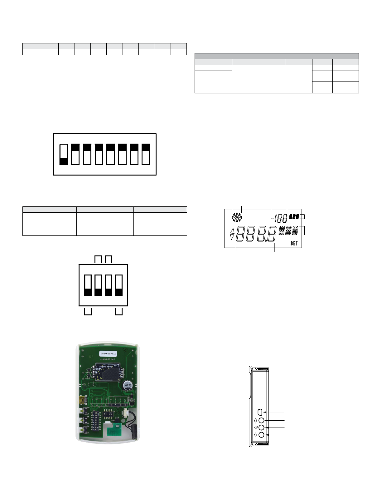
Use DIP Switch SW2 to congure the RS-485 MAC address of the device. The
address assignment is determined by adding the values for each of the switches that
are in the ON position Table 1 below.
Switch Position 1 2 3 4 5 6 7 8
Address Value 128 64 32 16 8 4 2 1
Table 1: Address value for each switch position
The CDTA and CDTC comes from the factory with all of the DIP switches, except
position 1, in the ON position as shown in Figure 4 below. The address of the transmitter
would be 127 as it would be 64+32+16+8+4+2+1 = 127. Another example would be
if the address desired was 008, the only DIP switch position in the ON position would
be position 5.
A valid address depends on the protocol selected. Valid BACnet addresses range
from 0 to 127. Valid Modbus® addresses range from 1 to 247. A valid and unused
address should be set before connecting to an existing network. The device will not
function properly if an invalid address is set. During the power up sequence, the LCD
(if present) will display the RS-485 address as the primary value with “ADR” as the
primary text and either “BAC” to indicate BACnet or “MOD” to indicate Modbus® as the
secondary text. If the RS-485 MAC address is invalid, the invalid value is shown as the
primary value with “ERR” as the primary text.
ON
1 2 3 4 5 6 7 8
Figure 4: DIP switch SW2 (center-left)
Use DIP Switch SW1 (see Figure 5) to congure other hardware and software options
per Table 2 below.
Switch On Off
1 – Menu Enable
2 – Protocol
3 – Reserved
4 – Terminating Resister
Access to the setup menu
is enabled
®
Modbus
120Ω between A[-] and B[+]
Access to the setup menu
is disabled
BACnet
Open
Table 2: DIP switch menu options
AUTO SERIAL CONFIGURATION
Auto serial conguration enables the device to determine the baud rate, parity and
stop bits directly from the serial trafc. This allows a device to be quickly and easily
deployed after a valid RS-485 MAC address is chosen. Note that the auto conguration
procedure assumes a serial conguration appropriate to the selected protocol as
follows:
SUPPORTED SERIAL CONFIGURATIONS
Protocol Supported Baud Rates Data Size Parity Stop Bits
BACnet 9600
®
Modbus
– RTU Even
19200
38400
57600
76800
115200
8 None 1
Odd
None 2
1
Table 3: Supported serial congurations
If this is not the case, then the serial communication must be congured manually in
the setup menu.
To activate auto serial conguration, set a valid RS-485 MAC address using DIP switch
SW2, connect the serial bus and power wires, and apply power. The device will power
up and begin examining the serial bus for communication.
When Modbus
network, it is necessary to generate trafc in order to congure the serial communication.
Attempting to read input registers is a good method to generate trafc. Note that while
serial conguration is in progress, the device may not respond to requests. The device
may require multiple read requests to complete the serial conguration process.
The auto serial conguration process will complete once a message addressed to the
device is received and processed successfully. The serial conguration parameters
are then saved to non-volatile storage and loaded by default each time the device
starts. If the serial conguration of the bus changes, a power cycle of the device is
required to restart the Auto Serial Conguration process.
®
is selected, and the device is setup ofine or away from the main
USER INTERFACE
PRESSED INDICATOR
VALUE
SECONDARY TEXT
PRIMARY TEXT
ON
1 2 3 4
MENU
NETWORK
Figure 5: DIP switch SW1 (bottom-center)
PRIMARY VALUE
Figure 7: Display layout
Home Screen
For models with the LDC display option, or when using the A-449A remote display tool,
the home (idle) screen displays up to two measured values and is the steady state
of the device. The information displayed on the home screen can be changed by the
“DSP” value in the setup menu.
Set Point
When idle, a single press of either the UP or DOWN button will display the current set
point value with the selected units displayed as the primary text. Additional presses of
the UP or DOWN buttons will increase or decrease the set point value by 1 degree.
A press and hold of the UP or DOWN button will initiate continuous changing of the
set point value. The set point display will timeout and return to the home screen after
5 seconds of inactivity. At this point the new set point value is stored in non-volatile
memory. The range of the set point value can be congured with “SOH” and “SOL”
values in the setup menu. A display is not required to change the set point value.
Override
When on the home screen or when changing the set point, the override button (middle
button) can be pressed. When the override button is pressed in these states, a snow
ake symbol is displayed momentarily to indicate the button was pressed.
REMOTE DISPLAY PO
UP
ENTER
DOWN
Figure 6: Internal view of transmitter
Figure 8: Side view of transmitter
Page 3
Setup Menu
The setup menu provides a means to congure the device locally. The setup menu can
only be entered if the Menu Enable switch is in the on position and a display is present
(local or remote). To enter the setup menu, press and hold the UP and DOWN buttons
for at least 3 seconds or until the display changes.
The setup menu contains a scrollable list of values that can be changed. Use the UP
and DOWN buttons to scroll through the available values. The scrollable list is circular
to allow continuous scrolling in either direction.
A value can be modied by rst scrolling to the desired value, then press and hold the
UP and DOWN buttons for at least 0.5 seconds, or until to word SET is displayed. The
value can now be changed with the UP and DOWN buttons. Numerical values are
displayed in the primary value area of the display with the current units in the primary
text area. Some settings are text based and only show values in the primary text area.
When the desired value is reached, press and hold the UP and DOWN buttons for
0.5 seconds to store the value in non-volatile memory and return to the setup menu.
The setup menu will timeout and return to the home screen after 30 seconds of
inactivity. The setup menu can also be exited manually by a press and hold of the
DOWN button for 0.5 seconds.
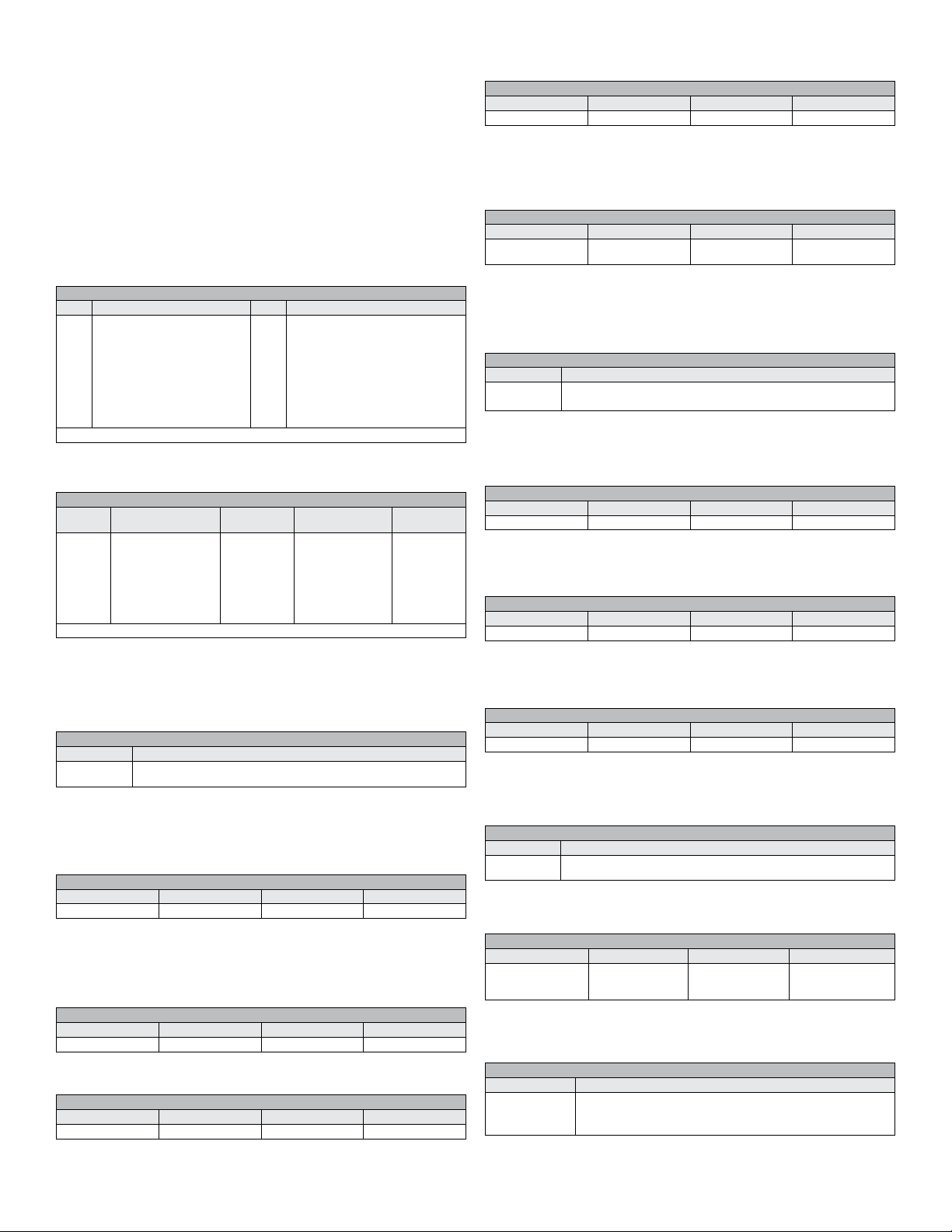
SETUP MENU VALUES
Value Description Value Description
MAX
Maximum CO
DSP
Home screen conguration
UNI
Units selection
SOL
Set point low limit temperature
SOH
Set point high limit temperature
LON
CO2 warning indicator limit
(Model dependent)
LOF
CO2 warning indicator off level
(Model dependent)
2 Value
BAR
Typical barometric pressure
ABC
Automated background calibration
OFH*
Relative humidity offset
OFT
Temperature offset
OFC
CO2 offset
AUT
Auto serial conguration
BAU
Baud rate selection
PAR
Parity selection
STP
Stop bits selection
RST
Reset to factory defaults
*Only the Series CDTA has humidity sensing capabilities.
Table 4: Setup values
Home Screen Conguration (DSP)
This value controls what information is displayed on the home screen.
DSP
Setting
Value
“CH”*
“CT”
“HT”*
“TS”
“S”
“T”
“H”*
“C”
Primary
Value
CO
2 concentration
CO2 concentration
Relative humidity
Temperature
Set point
Temperature
Relative humidity
CO2 concentration
Primary
Text
“PPM”
“PPM”
“%”
“°C” or “°F”
“°C” or “°F”
“°C” or “°F”
“%”
“PPM”
Secondary
Value
Relative humidity
Temperature
Temperature
Set point
Secondary
Text
“%”
“°C” or “°F”
“°C” or “°F”
“°C” or “°F”
*Only the Series CDTA has humidity sensing capabilities.
Maximum CO2 Value (MAX)
Displays the highest CO2 concentration value observed by the sensor since the last
power cycle or reset. Reset the MAX CO2 concentration by pressing and holding the
UP and DOWN buttons for 1 second.
Units Selection (UNI)
This value controls the units that data is displayed in.
Table 5: Display values
UNI
Setting Value Description
“US”
“SI”
US customary units (°F, in Hg)
International system units (°C, hPa)
Table 6: Unit values
Set Point Low Limit Temperature (SOL)
This value sets a lower limit on the current set point value. The set point low limit
value is a numerical setting that supports continuous change (increment/decrement)
by press and holding of either UP or DOWN button. If the new set point low limit
temperature is higher than the current set point temperature, then the set point
temperature will be set to the new set point low limit temperature.
SOL
Default Value Minimum Value Maximum Value Increment
20°C (68°F) 0°C (32°F) Set point high limit 1°
Table 7: Set point for low temperature limit
Set Point High Limit Temperature (SOH)
This value sets an upper limit on the current set point value. The set point high limit
value is a numerical setting that supports continuous change (increment/decrement)
by press and holding of either UP or DOWN button. If the new set point high limit
temperature is lower than the current set point temperature, then the set point
temperature will be set to the new set point high limit temperature.
SOH
Default Value Minimum Value Maximum Value Increment
35°C (95°F) Set point low limit 50°C (122°F) 1°
Table 8: Set point for high temperature limit
2 Warning Indicator Limit (Model Dependent) (LON)
CO
The CO2 concentration that will turn on the warning LED
LON
Default Value Minimum Value Maximum Value Increment
1100 PPM 0 PPM 9999 PPM 1 PPM
Table 10: CO
2 warning indicator on limit
CO2 Warning Indicator Off Level (Model Dependent) (LOF)
The CO2 concentration that will turn off the warning LED
LOF
Default Value Minimum Value Maximum Value Increment
1050 PPM 0 PPM 9999 PPM 1 PPM
Table 11: CO2 warning indicator off limit
Typical Barometric Pressure (BAR)
This value sets the typical barometric pressure for the location where the device
is mounted. The factory setting is for standard pressure at sea level. Adjusting the
barometric pressure gives a more accurate measurement, especially at higher
elevations.
BAR
Default Value Minimum Value Maximum Value Increment
1013 hPa
(29.9 inHg)
677 hPa
(20.0 inHg)
1016 hPa
(30.0 inHg)
1 hPa
(0.1 inHg)
Table 12: Elevation/barometric pressure compensation
Automated Background Calibration (ABC)
Enables/disables the Automated Baseline Correction algorithm for disabling in
locations that experience elevated levels of CO2 due to constant occupancy of the
area. Select “ON” to enable ABC and select “OFF” to disable ABC. Factory Default
is “ON.”
ABC
Setting Value Description
“ON”
“OFF”
Enables ABC algorithm
Disables the ABC algorithm
Table 13: Automated background calibration setting
Relative Humidity Offset (OFH)
This value, allows the relative humidity to be adjusted by a xed amount to match
another calibrated measurement. The display shows the current relative humidity
value plus any previous offset value.
RHU
Default Value Minimum Value Maximum Value Increment
0% -30% 30% 0.1%
Temperature Offset (OFT)
This value allows the temperature to be adjusted by a xed amount to match another
calibrated measurement. The display shows the current temperature value plus any
previous offset value.
Table 14: RH offset value
OFT
Default Value Minimum Value Maximum Value Increment
0° -30° 30° 0.1°
CO2 Offset (OFC)
This value allows the CO2 Concentration to be adjusted by a xed amount to match
another calibrated measurement. The display shows the current CO2 concentration
value plus any previous offset value.
Table 15: Temperature offset value
OFC
Default Value Minimum Value Maximum Value Increment
0 PPM -500 PPM 500 PPM 1 PPM
Table 16: CO
Auto Serial Conguration (AUT)
This value enables or disables the automatic baud rate detection. If the device fails to
communicate or the serial conguration is not one of the options in Table 3, then this
value should be set to “OFF”. The serial can then be congured manually.
2 offset value
AUT
Setting Value Description
“ON”
“OFF”
Baud Rate (BAU)
This value provides the selection of the desired serial baud rate. This value is only
visible when the value of AUT is “OFF”.
Auto baud enabled
Auto baud disabled
Table 17: Automatic baud rate value
BAU
Setting Value Baud Rate Setting Value Baud Rate
9.6 K
19.2 K
38.4 K
9,600
19,200
38,400
57.6 K
76.8 K
115.2 K
57,600
76,800
115,200
Table 18: Serial baud rate value
Parity Selection (PAR)
This value provides the selection of the desired serial parity. This value is only visible
when the value of AUT is “OFF”.
PAR
Setting Value Description
“NON”
“EVE”
“ODD”
No parity
Even parity
Odd parity
Table 19: Serial parity value
Page 4
Stop Bits Selection (STP)
This value provides the selection of the desired serial stop bits. This value is only
visible when he value of AUT is “OFF”
STP
Setting Value Description
1
2
Reset To Factory Defaults (RST)
This value, when set to “YES”, will reset all user settings to their default values and
reset the device. This applies to all settings including BACnet writable settings.
BACNET
BACnet installations should comply with ANSI/ASHRAE Standard
NOTICE
Refrigerating and Air-Conditioning Engineers, Inc., 2010
Communications wiring must be in a daisy-chain fashion. Star
NOTICE
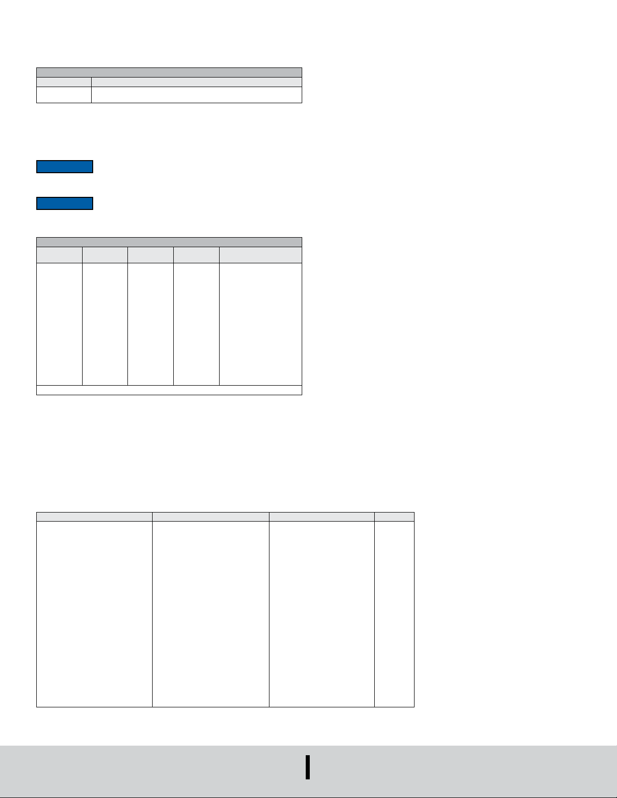
BACnet Object Overview
The device supports the following objects:
SUPPORTED BACNET OBJECTS
Object
Type
Device
Analog Input
Analog Input
Analog Input
Binary Value
Binary Value
Analog Value
Analog Value
Analog Value
Analog Value
Analog Value
Analog Value
Analog Value
Analog Value
Analog Value
Analog Value
Analog Value
*Only the Series CDTA has humidity sensing capabilities.
The default object identier is 607xxx, where xxx is replaced by the MS/TP MAC
address set by DIP switch SW2. The object identier value will change as the MS/TP
MAC address changes. However, if a specic object identier is written via BACnet,
then that value is stored and changes to the MS/TP MAC address will no longer affect
the object identier. Similarly, the default object name includes 607xxx. The object
name will reect the current object identier. If a specic object name is written via
BACnet, then that value is stored and changes to the object identier will no longer
affect the object name.
APDU Timeout values are rounded to the nearest second (1000ms). Values less than
500 will be rounded to 0 and Number of APDU Retries will be set to 0.
BACnet Objects
Device Object
Property Default Value Property Data Type Access
Object Identier
Object Name
Object Type
System Status
Vendor Name
Vendor Identier
Model Name
Firmware Revision
Application Software Version
Location
Description
Protocol Version
Protocol Revision
Protocol Services Supported
Protocol Object Types Supported
Object List
Active COV Subscriptions
Maximum APDU Length Supported
Segmentation Supported
APDU Timeout
Number of APDU Retries
Max Master
Max Info Frames
Device Address Binding
Database Revision
Serial Number (1000)
One stop bit
Two stop bits
Table 20: Serial stop bits value
135-2010 BACnet A Data Communication Protocol for Building
Automation and Control Networks, American Society of Heating,
connections and T connections are not permitted
Dynamically
Creatable
No
No
No
No
No
No
No
No
No
No
No
No
No
No
No
No
No
Dynamically
Deletable
No
No
No
No
No
No
No
No
No
No
No
No
No
No
No
No
No
Object
Identier
607xxx
AI1
AI2
AI3
BV1
BV2
AV1
AV2
AV3
AV4
AV5
AV6
AV7
AV8
AV9
AV10
AV11
607xxx
“CDTA IAQ 607xxx”
DEVICE(8)
Operational(0)
“Dwyer Instruments, Inc.”
607
“CDTA-???0-???”
“?.?”
“?.?”
“All-in-One CO2/RH/Temp/SetPoint”
1
12
See PICS
See Table 2
See Table 2
480
NO_SEGMENTATION (3)
6000
3
127
1
Empty
1
Object
Name
CDTA IAQ
CO
2 concentration
Relative humidity*
Temperature
Override
Use SI units
Set point
Set point low limit
Set point high limit
Dew point
Wet bulb
Specic enthalpy
Display mode
CO2 Offset
Barometric pressure
Relative humidity offset*
Temperature offset
BACnetObjectIdentier
CharacterString(32)
BACnetObjectType
BACnetDeviceStatus
CharacterString
Unsigned
CharacterString
CharacterString
CharacterString
CharacterString(32)
CharacterString(32)
Unsigned
Unsigned
BACnetServicesSupported
BACnetObjectTypesSupported
BACnetArray
List of BACnetCOVSubscription
Unsigned
BACnetSegmentation
Unsigned
Unsigned
Unsigned
Unsigned
BACnetAddressBinding
Unsigned
CharacterString
Read/Write
Read/Write
Read
Read
Read
Read
Read
Read
Read
Read/Write
Read/Write
Read
Read
Read
Read
Read
Read
Read
Read
Read/Write
Read/Write
Read/Write
Read/Write
Read
Read
Read
DWYER INSTRUMENTS, LLC
P.O. BOX 373 • MICHIGAN CITY, INDIANA 46360, U.S.A.
Modbus® is a registered trademark of Schneider Electric USA, Inc.
Printed in U.S.A. 9/22 FR# 444131-10 Rev. 3©Copyright 2022 Dwyer Instruments, LLC
Phone: 219-879-8000
Fax: 219-872-9057
www.dwyer-inst.com
e-mail: [email protected]
 Loading...