

Page 1
Page | 1
CONFIDENTIAL
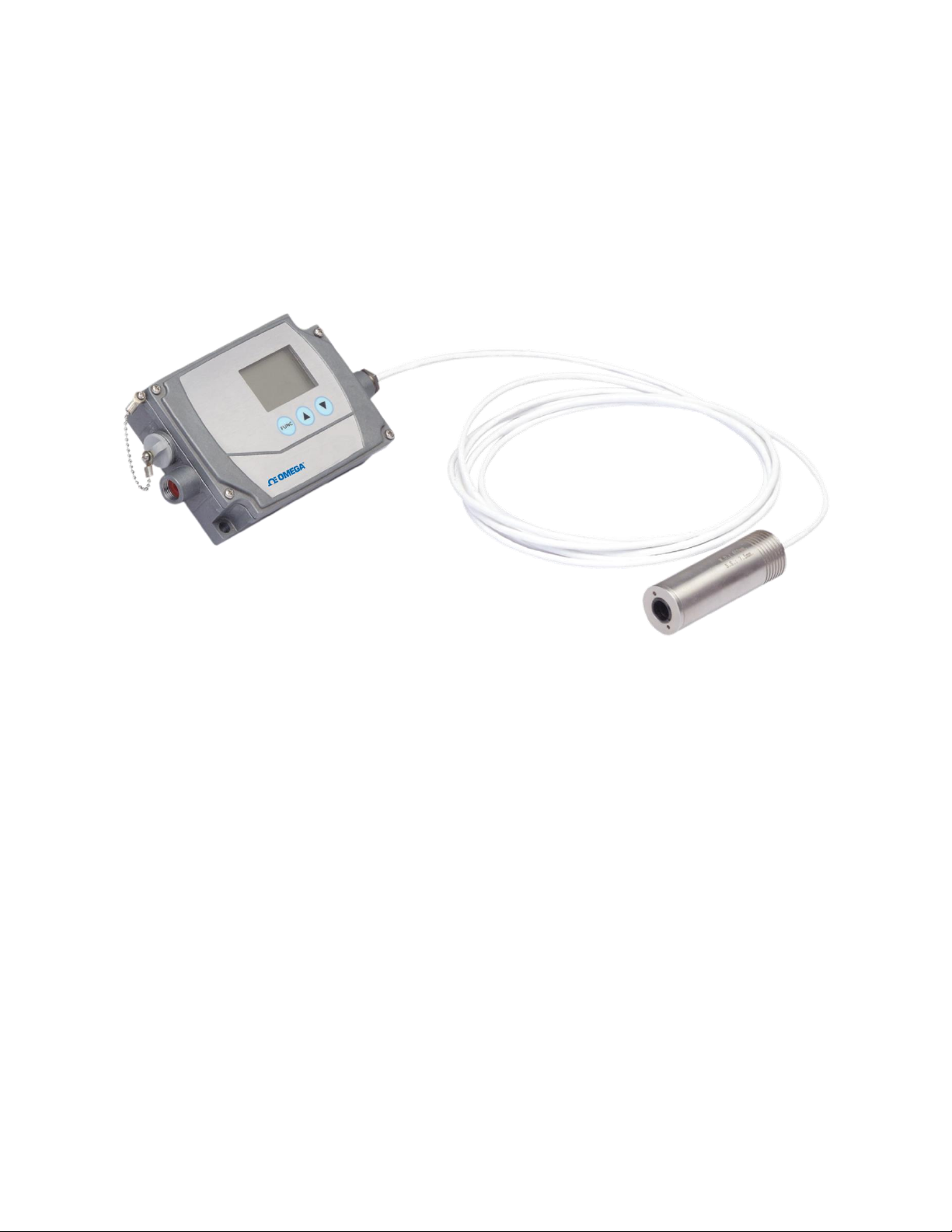
OSAO-Series
Adjustable Output, Ultra Fast Response, Fixed IR
Sensors with built-in display
AST -
Accurate Sensors
Technologies
AO250 Model
Page 2

Page | 2
CONFIDENTIAL
Index
1. Chapter - 1
General information
2. Chapter - 2 ....................................................................................................................... 2
Introduction
2.1 Application, range and working principle
3. Chapter - 3 ....................................................................................................................... 3
Technical specification
4. Chapter - 4 ....................................................................................................................... 4
Setting at the instrument
4.1 Operation
4.2 Adjustment parameters
4.3 Connection diagram
4.4 Pin assignment
5. Chapter - 5 ....................................................................................................................... 7
Optics
5.1 Sensor head details
5.2 Optical specification
6. Chapter - 6 ....................................................................................................................... 8
Accessories
6.1 Electrical accessories
6.2 Mechanical accessories
7. Chapter - 7 ....................................................................................................................... 11
Software installation
7.1 Installation
7.2 Parameter in main screen
8. Chapter - 8 ....................................................................................................................... 18
Calculate spot size
9. Chapter - 9 ....................................................................................................................... 19
Serial communication protocol
Page 3

Page | 3
CONFIDENTIAL
Chapter - 1
General Information
We are pleased that you have chosen this high quality and highly efficient OSAO-Series pyrometers for
non-contact temperature measurement.
Please read this manual carefully, step by step before performing any operation with the Pyrometer. It
contains all the necessary instructions for set up and operation of the pyrometer. When operating the
instrument, it is necessary to follow the general safety instructions.
1.1 Safety Measures
This section provides an overview about important safety regulations.
1.1.1 General
Each person working with the pyrometer must have read the user manual before operation. The
Pyrometer has only to be used for the purpose described in the manual.
1.1.2 Safety Precaution
The Pyrometer works only with a potential-free low voltage of range 24V DC. This voltage is not harmful
for the user.
1.1.3 Maintenance and use of Pyrometer
Pyrometer can be operated by the qualified person who has got instructions from the supervisor. It is
strongly prohibited to do technical modifications of the device without permission of the manufacturer.
1.1.4 Environmental Protection
The lens or its coating may contain harmful materials and hence it should not be disposed of with
normal waste.
1.1.5 Packaging and storage
Always use a shock-proof package for shipment of the pyrometer. It should be sealed to protect it
against humidity. Also protect the lens of the pyrometer with a cover. They should be stored at the
temperature ranges from -20 °C (68 °F) to +70 °C (158 °F).
Page 4
Page | 4
CONFIDENTIAL
Chapter - 2
Introduction
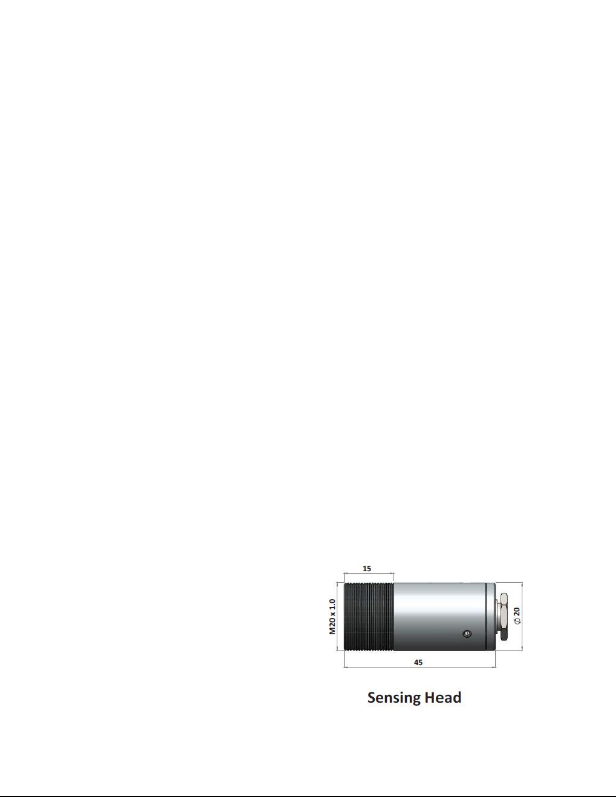
The AO250 model is a highly economic digital IR pyrometer with extended sensor head and separate
electronic box for non-contact temperature measurement of metals, ceramics, graphite, etc. in
temperature ranges between 250 °C (482 °F) and 1800 °C (3272 °F).
The AO50/50H model is specially designed digital pyrometer in 4 wire technology with extended optical
head which can withstand high ambient temperature up to 120 °C (248 °F) and 180 °C (356 °F) (AO50H).
It has inbuilt LCD & keypad for parameterization to provide high performance and low maintenance of
non contact temperature measurement in demanding industrial environment.
2.1 Application, Range and Working Principle
The OSAO-Series pyrometers are especially designed for industrial purposes. The AO250 model is
suitable for high temperature measurement ranging from 250 °C (482 °F) to 1800 °C (3272 °F). The
AO50/50H pyrometers are suitable for high temperature measurement ranging from 0 °C (-32 °F) to 800
°C (1472 °F).
OSAO-Series IR Pyrometers are two-piece measurement systems containing one extended sensor head
and one electronic box. The electronic box comes with built-in 4 digit LCD display which offers many
signal processing features. The Keypad on the electronic box helps in setting parameters like Emissivity,
Analog Sub range, Relay, Set point, Hysteresis (Hyst), Analog Output, Unit of temp(°C or F), Response
Time, Peak Picker and Sensor address etc. The sensor head is un-effected by electromagnetic
interferences. The use of the serial interface and the provided software temperature can be displayed
and stored in a PC where parameterizing can also be done.
AO250 model has response time of 2 msec adjustable up to 10 sec and has USB 2.0 (RS-232 / RS-485
Optional) outputs. Instrument can be powered directly through USB without any external power supply.
The pyrometer temperature measurement method utilizes the fact that objects emit thermal radiation
in an amount that directly corresponds to their own temperature and surface emissivity.
The pyrometer sensor detects the amount of infrared radiation emitted by the measured object (target).
The infrared signal is analyzed and the temperature it represents is analyzed by built-in microprocessor.
The applications in which OSAO-Series
pyrometers can be used are:
Plastic & rubber
Ceramic
Paper
Textile
Fluids
Oxide/Painted metal surface
Wood & glass industries
Page 5

Page | 5
CONFIDENTIAL
Chapter - 3
Technical Specifications
Model
OS-AO50-*
OS-AO50H-*
OS-AO250-*
Temperature Range
0°C….800 °C (1472 °F)
0°C….800 °C (1472 °F)
250 °C (482 °F)….1000°C
300°C….1300°C
350°C….1800 °C (3272 °F)
(dependent of FOV)
Spectral Response
8…14 μm
8…14 μm
1.6 μm
Photodetector Type
Thermopile
Thermopile
InGaAs
Field of View (FOV)
2:1 or 15:1
2:1 or 15:1
20 : 1, 40 : 1, or 80 : 1
Emissivity (ε)
0.1….1.2 adjustable
0.1….1.2 adjustable
0.1….1.0 adjustable
Response Time
20 msec adjustable up to 10 sec
60 msec adjustable up to 10
sec
2 msec adjustable up to 10 sec
Accuracy
± 1% of the measured value or
3°C whichever value
is greater (The sensor head
must be at constant
ambient temperature for a
minimum of 15 minutes)
±1.5% of the measured value
or 2°C whichever is
greater (The sensor head must
be at constant
ambient temperature for a
minimum of 15 minutes)
Below 1500°C : ±0.3% of the
measured value +1°C
Above 1500°C : ±0.4% of
the measured value +1°C
Repeatability
0.3% of reading in °C + 1°C
0.3% of reading in °C + 1°C
0.1% of reading in °C +1°C
Temperature
Coefficient2
± 0.06 °C/°C (± 0.06 °F/°F ) or ±
0.06 %/°C (0.06
%/°F) (whichever is greater)
± 0.06 °C/°C (± 0.06 °F/°F ) or ±
0.06 %/°C (0.06
%/°F) (whichever is greater)
± 0.055 °C/°C (± 0.055 °F/°F ) or
± 0.055 %/°C (0.055 %/°F)
(whichever is greater)
Sighting Option
None
None
Laser Pilot Light(PL)
Analog Output
0-20mA, 4-20mA, 0-10V,
Thermocouple Type “K” or “J”
(User selectable)
0-20mA, 4-20mA, 0-10V,
Thermocouple Type “K” or “J”
(User selectable)
0-20mA, 4-20mA, 0-10V(User
Selectable)
Digital Output
USB 2.0
RS-232/RS-485 interface card
(Optional)
*At a time only one digital
output possible
USB 2.0
RS-232/RS-485 interface card
(Optional)
*At a time only one digital
output possible
USB 2.0 output
RS - 232 / RS - 485 interface
card (Optional)
*at a time only one digital
output possible
Operating Temp.
Range
Electronic Box up to 70°C
Sensor head up to 120 °C (248
°F)
Electronic Box up to 70°C
Sensor head up to 180 °C (356
°F)
Electronic Box and Sensor Head
up to 70°C
Storage Temp. Range
-20°C…70°C
-20°C…70°C
-20°C….70°C
Relay Output
Relay Output with hysteresis
60V DC/42V AC RMS,0.4A
Relay Output with hysteresis
60V DC/42V AC RMS,0.4A
Relay output with hysteresis
60V DC / 42V AC RMS,
0.4A
Adjustable Parameters
and Features via
Software
Emissivity, Response Time,
Clear Time (Peak Picker),
Analog Output, Sub Range, Unit
Of Temperature
(°C/°F), Communication
mode(Comm.mode), Record
feature etc.
Emissivity, Response Time,
Clear Time (Peak Picker),
Analog Output, Sub Range,
Unit Of Temperature
(°C/°F), Communication
mode(Comm.mode), Record
feature etc.
Emissivity, Response Time,
Clear Time(Peak Picker),
Analog Output, Analog
Scale(sub range), Unit of
Temperature(°C/°F),
Communication mode(Comm.
mode), Record Feature etc.
Adjustable Parameters
and Features via
Keypad
Emissivity, Setpoint, Hysteresis
(Hyst), Analog Sub
Range, Analog Output, Unit of
temperature, Sensor
address, Response Time, Clear
Time (Peak Picker) etc.
Emissivity, Setpoint, Hysteresis
(Hyst), Analog Sub
Range, Analog Output, Unit of
temperature, Sensor
address, Response Time, Clear
Time (Peak Picker) etc.
Emissivity, Set Point, Hysteresis
(Hyst), Analog Sub
Range, Analog Output, Unit of
temperature, Sensor
address, Response Time, Clear
Time (Peak Picker)
etc.
Page 6
Page | 6
CONFIDENTIAL
Power Supply
12V to 28V DC with reverse
polarity protection
12V to 28V DC with reverse
polarity protection
24V DC
Power Consumption
Max 2.5 watt
Max 2.5 watt
Max 2.5 watt
Laser Power
Not applicable
Not applicable
<1 m watt
Protection Class
IP65
IP65
IP65
Housing
Sensor head-Stainless Steel;
Electronic Box: Zinc
Sensor head-Stainless Steel;
Electronic Box: Zinc
Sensor Head : Stainless Steel
Electronic Box : Zinc
Isolation
Power supply, *Digital output
and Analog output are
galvanically isolated against
each other
* Not applicable for USB 2.0
digital output
Power supply, *Digital output
and Analog output are
galvanically isolated against
each other
* Not applicable for USB 2.0
digital output
Power supply, * Digital output
and Analog output are
galvanically isolated against
each other
*Not applicable for USB 2.0
digital output
Operating Humidity
10-95%, Non-Condensing
Conditions
10-95%, Non-Condensing
Conditions
10-95%, Non-Condensing
Conditions
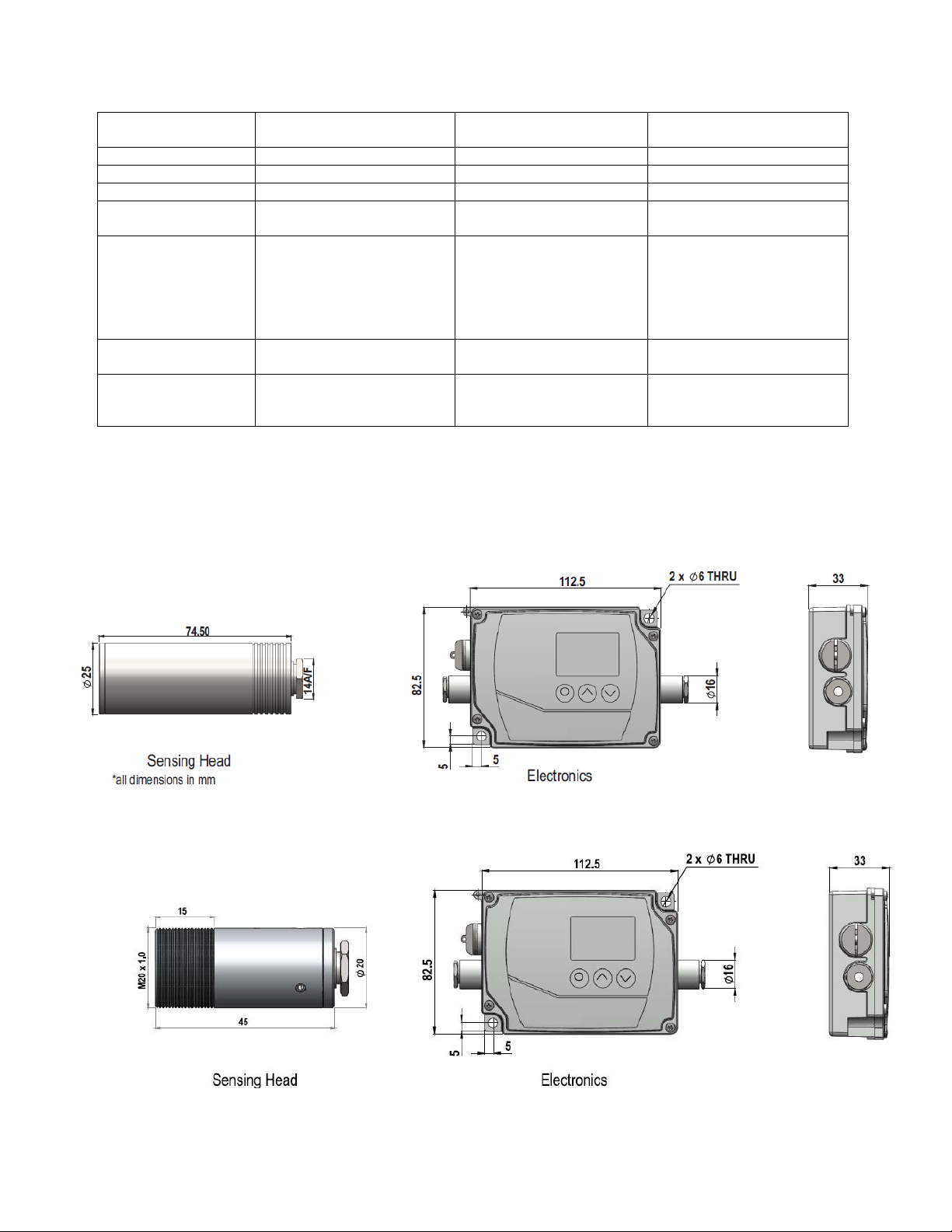
Weight & Dimensions
600g
112.5mm x 82.5mm x 33mm (L
x W x H)
600g
112.5mm x 82.5mm x 33mm (L
x W x H)
600g
112.5mm x 82.5mm x 33mm (L
x W x H)
Note:
1 : At ambient temperature 23 ± 5°C, ε=1 and response time = 600msec.
2 : For ambient temperature (sensor head) <18°C and >28°C.
Dimensions
AO250 Model
AO50/50H Models
Page 7
Page | 7
CONFIDENTIAL
Chapter-4
Setting at the instrument
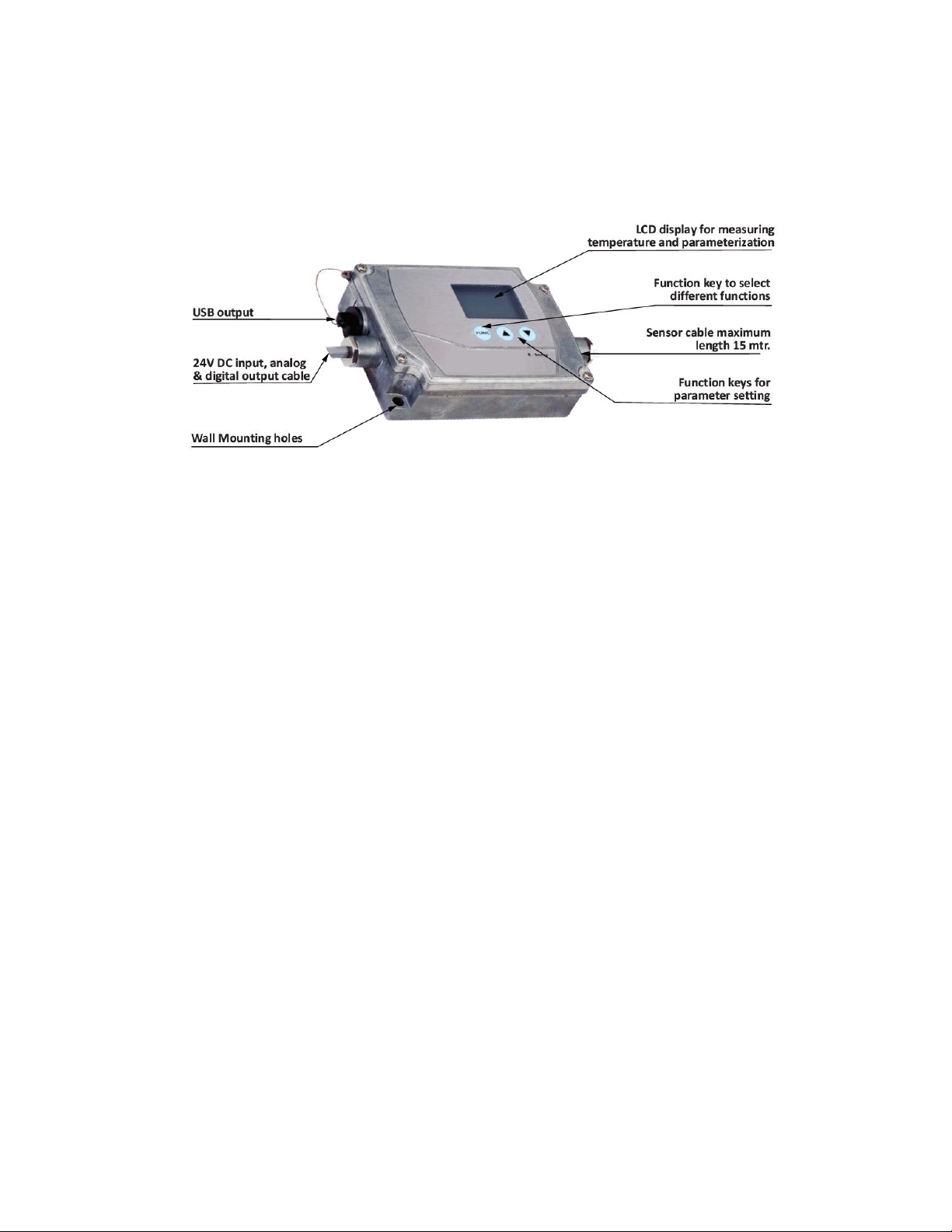
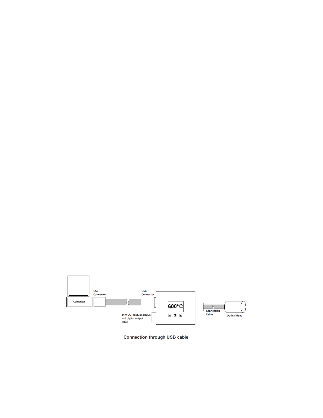
User can power up the unit either by USB input or by using connection cable at 24V DC input.
After power up sensor starts an initializing routine for some seconds. After this the object temperature
is shown in the display. User must remove the screw (mark USB in figure) to connect the unit with PC via
USB cable.
4.1 Operation
The programming keys FUNC, UP and DOWN enable the user to set the device on-site. Normally,
LCD shows temperature or error. To view different parameter FUNC key is pressed repeatedly. To
change values of parameters UP & DOWN keys are used. After changing values in any parameter by UP
& DOWN key finally FUNC key should be pressed to save that value in device. If FUNC key is not pressed
after changing parameter value than device will automatically take the old value & device will start
showing temperature. If any key is not pressed for more than 5 seconds than device will automatically
show the temperature.
For targeting LED light is provided in device (AO250 Model Only). Press UP + DOWN key
simultaneously to change the present condition of LED (ON / OFF).
4.2 Adjustable parameters
Emissivity: It is the relationship between the emissions of a real object and the emission of a black body
radiation source at the same temperature. For a correct measurement it is necessary to adjust emissivity.
Emissivity depends on the surface condition of the material, the spectral range of the pyrometer and the
measuring temperature. Different material has different emissivity ranging from 0.1 to 1.2 (0.1 to 1.0 for
AO250 Model). User can change emissivity by given keypad on the instrument.
Set point : Instrument is equipped with a relay contact controlled by the measuring signal. The turn on
temperature of relay is adjusted within the measuring range. The relay contact is “OPEN”
below the adjusted value, it is “CLOSE” above it.
Page 8
Page | 8
CONFIDENTIAL
Hysteresis (Hyst.) : The relay contact close when temperature exceeds the set point. It opens only if the
temperature falls below a value which consists of set point and the adjusted hysteresis. It can
be adjusted from 2 °C (35.6 °F) to 20 °C (68 °F).
Example : if set point value is 500°C and Hysteresis set to 10. Then relay operation as below mentioned:
1. Relay contact OPEN below 500°C temperature.
2. Relay contact CLOSE above 510°C temperature.
3. Once relay contact CLOSED than relay contact is OPEN's when temperature falls below 490°C.
Ana. Sub range LO : Analog sub-range is adjustable within the basic range, user can set lower analog
sub-range here.
Ana. sub range HI : User can set the analog sub-range higher value here. Minimum span between lower
& higher value is 51°C.
Analog output : User can select the output from 4…20mA or 0…20mA or 0…10V and T/C K-type or J-type
for AO50/50H Models
Temp. Unit : User can select °C or °F unit.
Sensor address : For communicating with pyrometer via software users have to give an address. The
address may be 1 to 255.
Response time : The response time can be set according to specified response range of device.
Picker : Please refer to chapter 7.
Head temp. : It shows the temperature of head.
Internal temp. : It shows the internal temperature of pyrometer.
4.3 Connection diagram
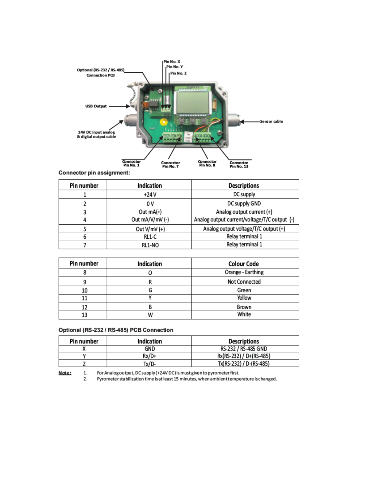
Note :- When the Pyrometer is only powered through USB, the Analog output, LED/Laser and Relay
Function not available.
Page 9
Page | 9
CONFIDENTIAL
4.4 Pin assignment
Page 10
Page | 10
CONFIDENTIAL
Chapter-5
Optics
The pyrometer measure temperature by receiving heat radiation, from the object, whose
temperature must be measured. This heat radiation is passes through the lens to the sensor and is then
converted to an electrical signal. The farther the measured object is from the pyrometer, the larger the
area that will be measured by the pyrometer. Depending on customer need, the pyrometer is designed
for different FOV. User must select the FOV while ordering.
Contamination on lens will cause inaccurate temperature reading therefore air purge unit is
used for sensor head. Cleaning with dry cloth is sufficient for lens cleaning.
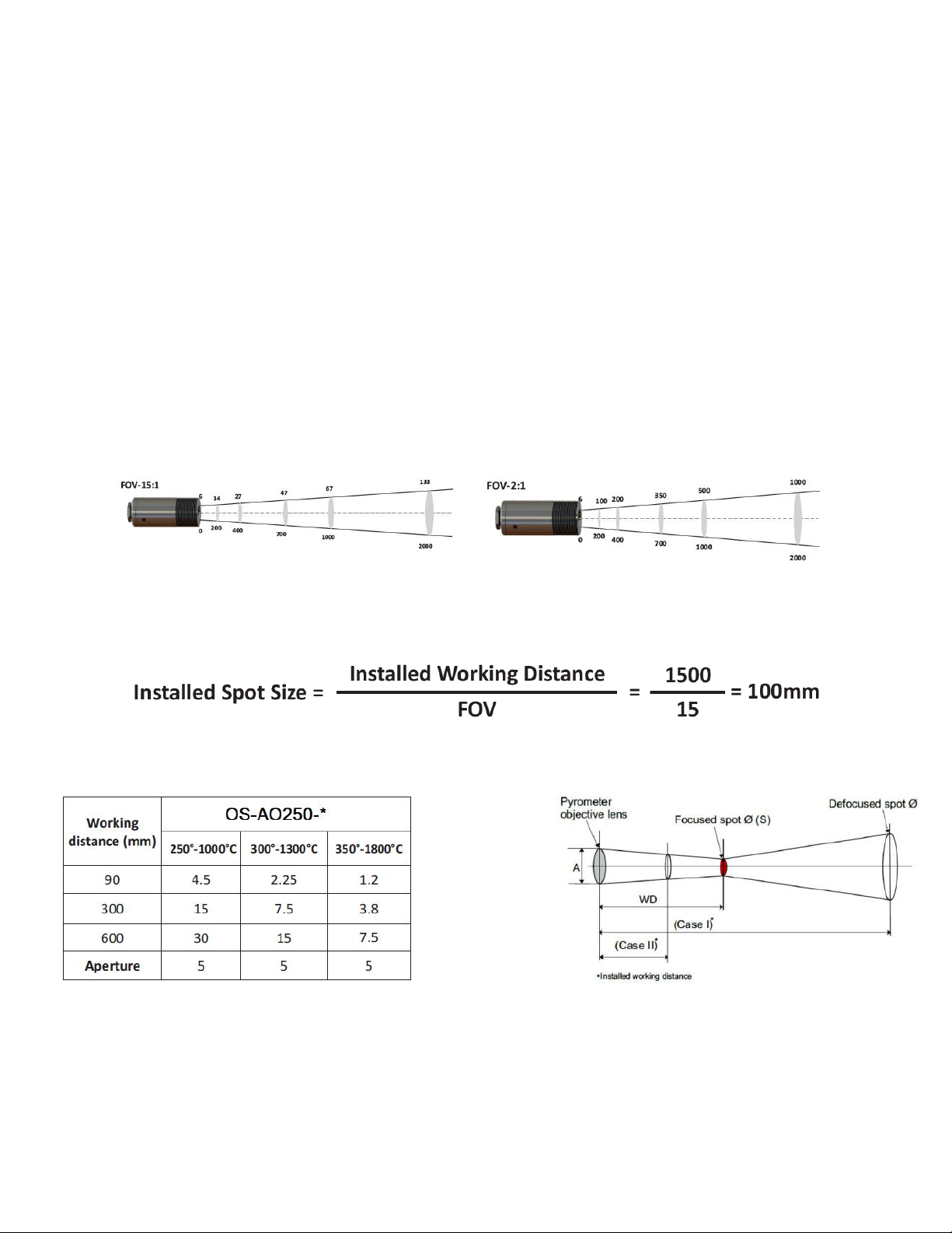
5.1 Optical specification (AO50/50H Models)
*FOV mentioned on the pyrometer.
For example: If pyrometer FOV is 15:1, then spot size at 1500mm calculated as given below method
except that minimum spot should be 6mm.
5.2 Optical specification (AO250 Model)
* Manufactured working distance (WD) mentioned on the pyrometer.
Page 11
Page | 11
CONFIDENTIAL
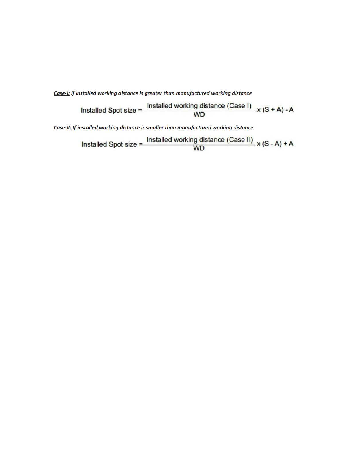
If the pyrometer is not installed at manufactured working distance (WD) then spot size at actual
installed distance should be calculated. For example, if factory made working distance is 300mm and
pyrometer OS-AO250-201-300 (350°C (662 °F) - 1800 °C (3272 °F)), then spot size is 3.8mm (as given in
table). If user installed this pyrometer at 600mm then spot size is not 7.5mm (as given in table), user
should have to calculate as given below method.
Page 12
Page | 12
CONFIDENTIAL
Chapter - 6
Accessories
6.1 Electrical Accessories
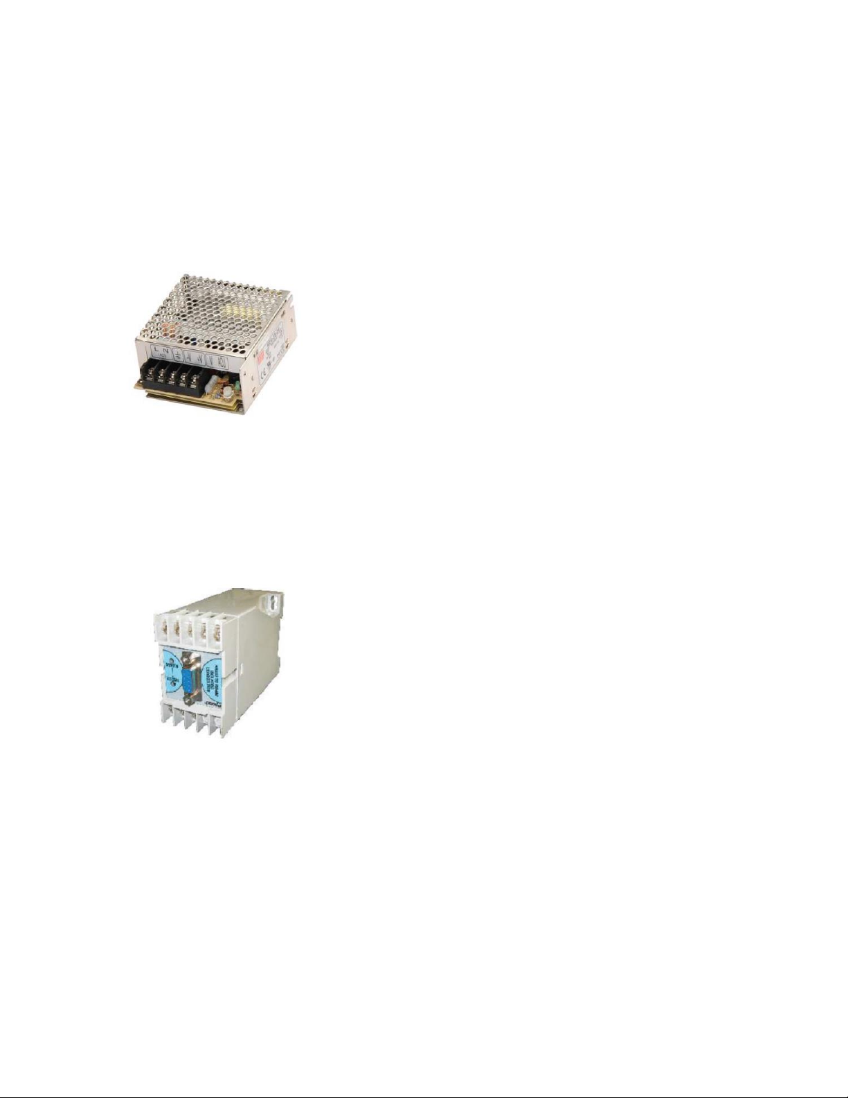
6.1.1
Power supply unit for OSAO-Series
(Reference no: OSAO-PS)
The input power supply is 110/230V AC check the polarity
before connecting the device.
6.1.2
Converter RS-232 ↔ RS-485 for OSAO-Series
(Reference no: OSAO-Conv)
The pyrometer can communicate with PC using RS-485 or RS-232.
RS-232 is used only for short distances.
RS-485 is well suited for long distance transmission. Standard on PC
is RS-232, so a converter is used which converts RS-485 to RS-232.
Page 13
Page | 13
CONFIDENTIAL
6.2 Mechanical Accessories
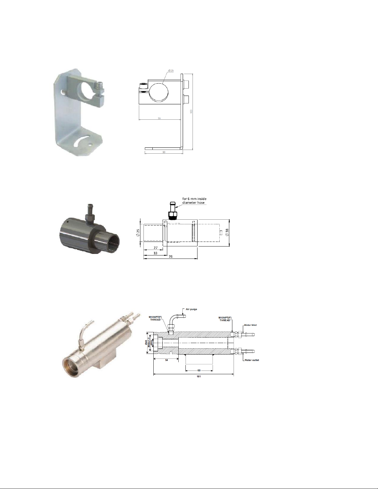
6.2.1
Adjustable mounting support for AO250 Models
(Reference no: OS-AO250-MT)
6.2.2
Air purge unit for sensor head for AO250 Models
(Reference no: OS-AO250-AP)
6.2.3
Water cooling jacket with air purge for AO250 Models
(Reference no: OS-AO250-WCJ-AP)
Water pressure : < 10 bar
Air pressure : < 0.5 bar
Dry and clean air (oil and dust free)
Air consumption : 2...3 m³/h
Ambient temperature : < 180 °C (356 °F)
Metal : Stainless steel
Weight : 0.45 Kg
Page 14
Page | 14
CONFIDENTIAL
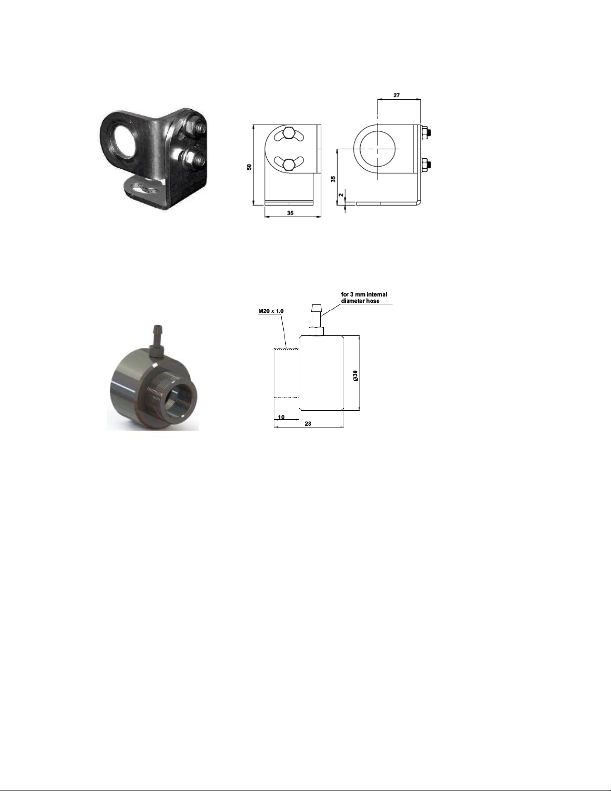
6.2.4
Adjustable mounting for AO50/50H Models
(Reference no: OS-AO50-MT)
6.2.5
Air purge unit for AO50/50H Models
(Reference no: OS-AO50-AP)
Page 15
Page | 15
CONFIDENTIAL
Chapter - 7
Software Installation
The provided Omega software “OmegaSoft” offers digital PC interface using RS-232 RS-485 &
USB 2.0. Using this software we can set all the parameters like response time, analog scale, emissivity,
clear time, communication mode. This software provide all necessary information about pyrometer.
4.1 Installation
Install the pyrometer software using the installation guide file on CD ROM & restart your PC as
per guidelines provided for installation. After installation of the software; Double click the application. It
will open the screen of software.
4.2 Parameters in main screen
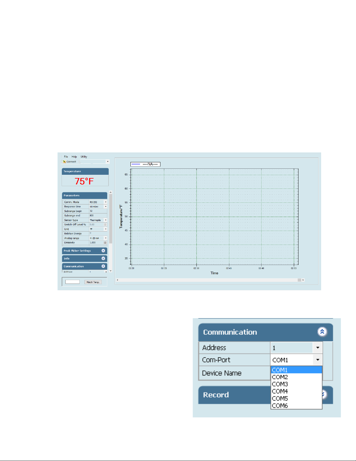
4.2.1 Communication
Communication between the OSAO-Series
pyrometer and the software is implemented via a cable
connected between the pyrometer and the PC serial
port. This enables the acquisition and recording of data,
as well as the transfer of commands from the software
application to the pyrometer. Communication can be
done by clicking on “Communication panel" and select
correct COM Port address where pyrometer is
connected. Also user has to select address of the
pyrometer (Example: Default 01/ printed on the
pyrometer sticker). Then click on CONNECT Button.
Page 16
Page | 16
CONFIDENTIAL
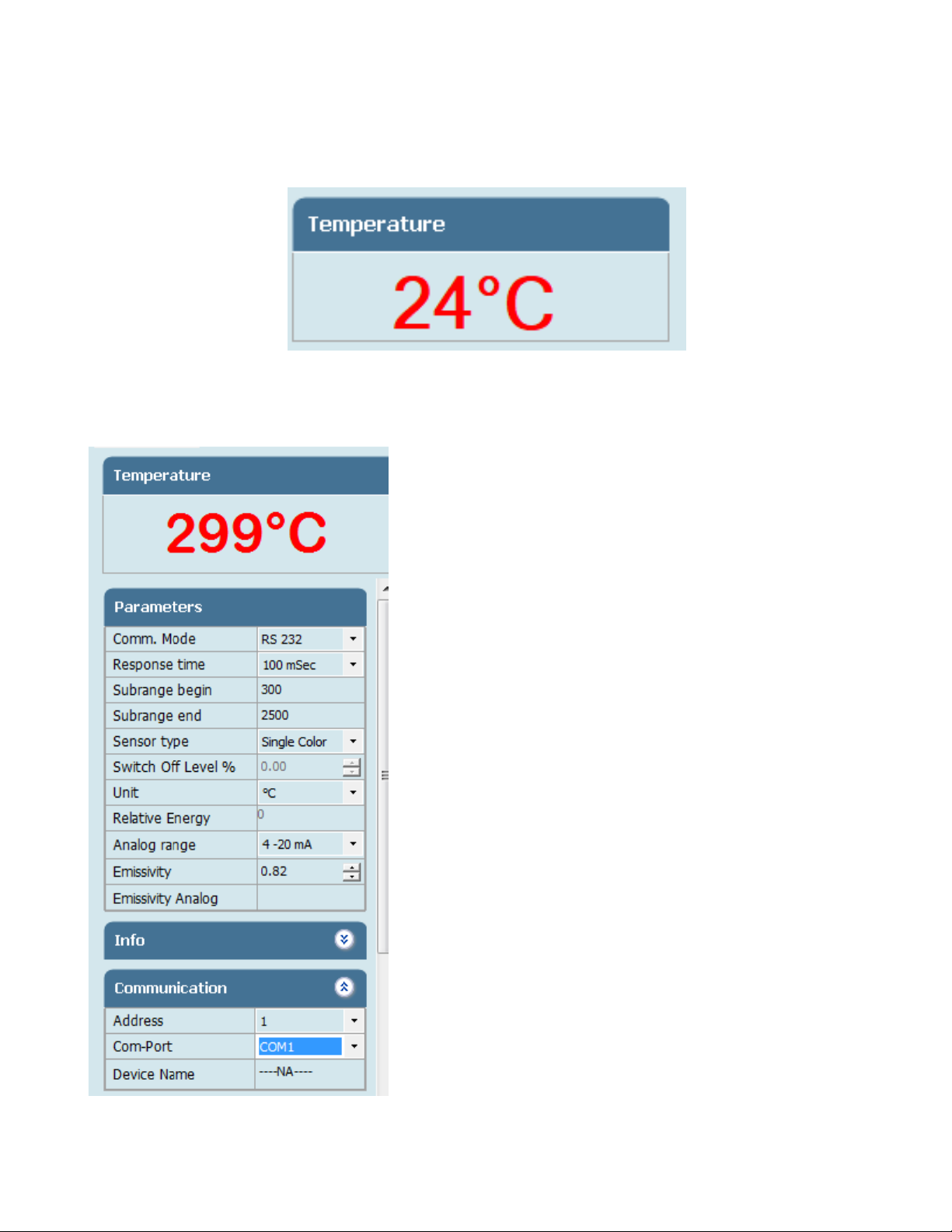
4.2.2 Temperature
It shows the temperature measured by the pyrometer
4.2.3 Parameter Setting
All user selectable device parameters can be set by using the software in the Panel "Parameter"
(A)Emissivity settings The emissivity can be set by clicking on
"Parameters” and select or type in the desired emissivity
directly in the description field. The emissivity value will be
transferred to pyrometer by hitting the "TAB " button.
(B)Response time The desired response time can be chosen in
the panel Parameter by clicking the appropriate list box (as per
the values available in the drop box of response time). This
parameter is use to set the analog response time of
pyrometer.
(C)Sub Range Begin & Sub Range End User can change the sub
range of pyrometer in the panel Parameter. Sub range must be
within the basic range of pyrometer, the minimum span
between higher & lower range is 51. Analog output will be
automatically set according to the sub-range by hitting "TAB"
button.
(D)Sensor Type It shows pyrometer sensor type. User can
change sensor type from two color to single color and vice
versa (only applicable with two color pyrometer). (only
applicable with two color pyrometer).
(E)Switch off level% ( for two color pyrometer) The switch of
level is the function that is used to avoid measurement errors
caused by signals, which are too low. Although factory default
is set to 15 %, the switch off limit can be adjusted between 2
and 50%.
(F)Unit User can change the measuring unit of temperature
from “Centigrade" to “Fahrenheit" and vice versa.
Page 17
Page | 17
CONFIDENTIAL
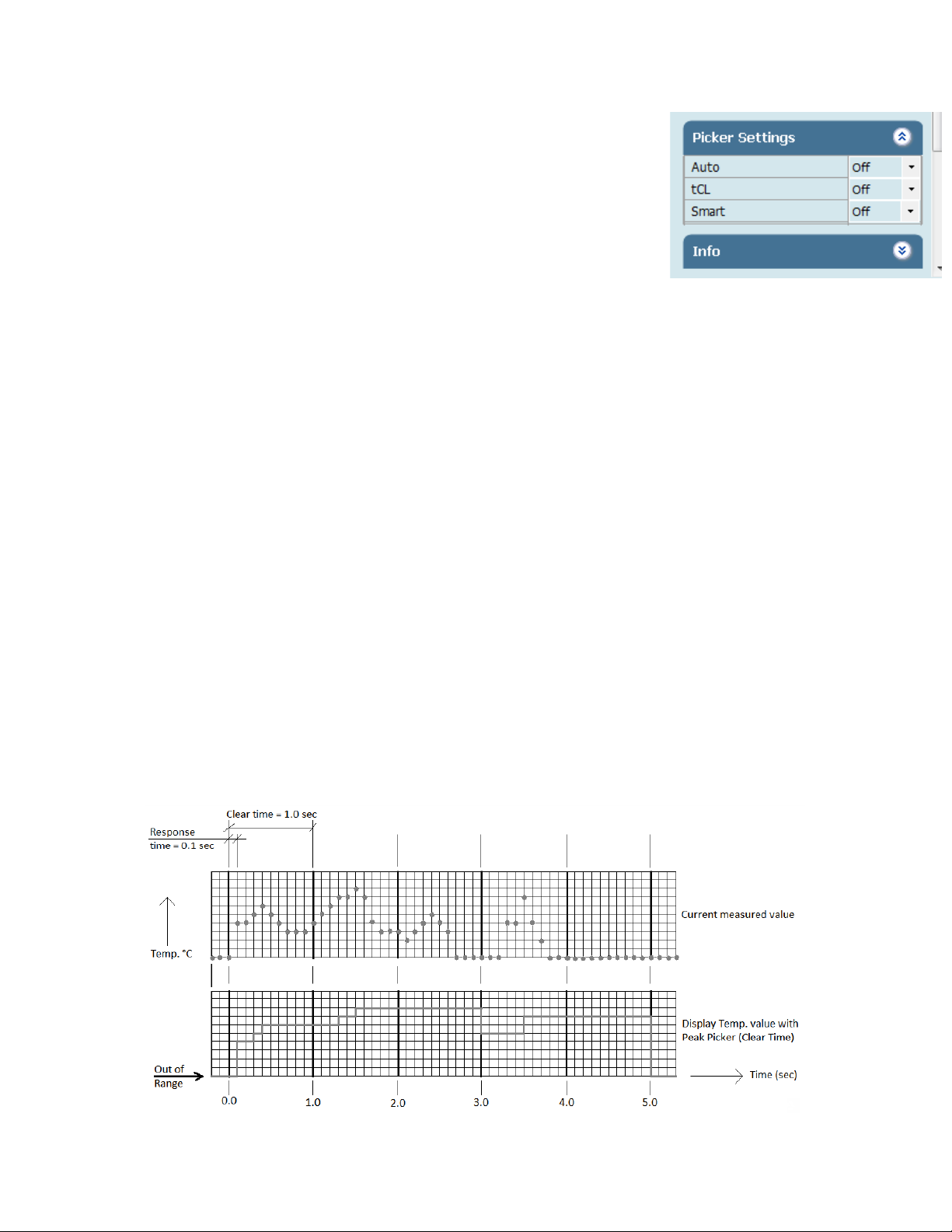
(G) Peak Picker Setting Three Pickers are available in Pickers setting menu
(Auto, tCL, Smart) & user can switch on any as per requirement, one at a time.
(G1) Auto “Auto” mode is used for discontinuous measuring task, such as
object being transported on a conveyer belt in such a case the maximum
value for each object has to be indicated. when the object passes the
measuring beam of the pyrometer, the maximum value is stored until a new
hot object appears in the measuring beam. The temperature which has to be recognized as “hot” is
defined by the low limit of the adjusted sub range. The stored maximum value will be deleted when the
temperature of the new hot object exceeds the low limit “from” of the sub range by at least 1°C. If a
lower limit is not entered, the maximum value storage will be deleted whenever the low level of the full
measurement has been exceeded.
(G2) Clear time (tCL) If the peak picker is switched on, the highest last temperature value will always be
displayed and stored. As such, it may be beneficial to periodically clear and reset the stored values in
order to obtain new temperature readings.
Example : If we set the tCl a s “6 sec” the highest last temperature value will be display for 6.0 sec to 12
sec then it capture next pick.
The following setting are possible :
OFF : At clear time “OFF” the maximum value storage is switched off and only momentary values are
measured.
tCL (10msec...25sec) : Clear Time tCL can be set between 10msec and 25sec. When set, estimates the
maximum values and holds it in two buffer memory. After the entered time, the storage will be deleted.
Clear Time feature is particularly useful when object temperature is not uniform across its dimension or
the pyrometer is not constantly viewing an object to be measured. The peak picker works on two buffer
memory to find maximum value over a defined interval. With the first memory, the highest measured
value is held and is deleted alternately in the time interval set (clear time). The other memory retains
the maximum value throughout the next time interval. The disadvantages of fluctuations in the display
with the clock frequency are thereby eliminated.
Page 18
Page | 18
CONFIDENTIAL
Note:
The maximum value storage coincides with adjustments made to response time. Therefore:
(I) Clear time<= the adjusted response time is useless
(ii) Clear times must be at least 5 times longer than the response time.
(iii) Only maxima with full maximum value can be recorded, which appear at least 5 times longer than
response time.
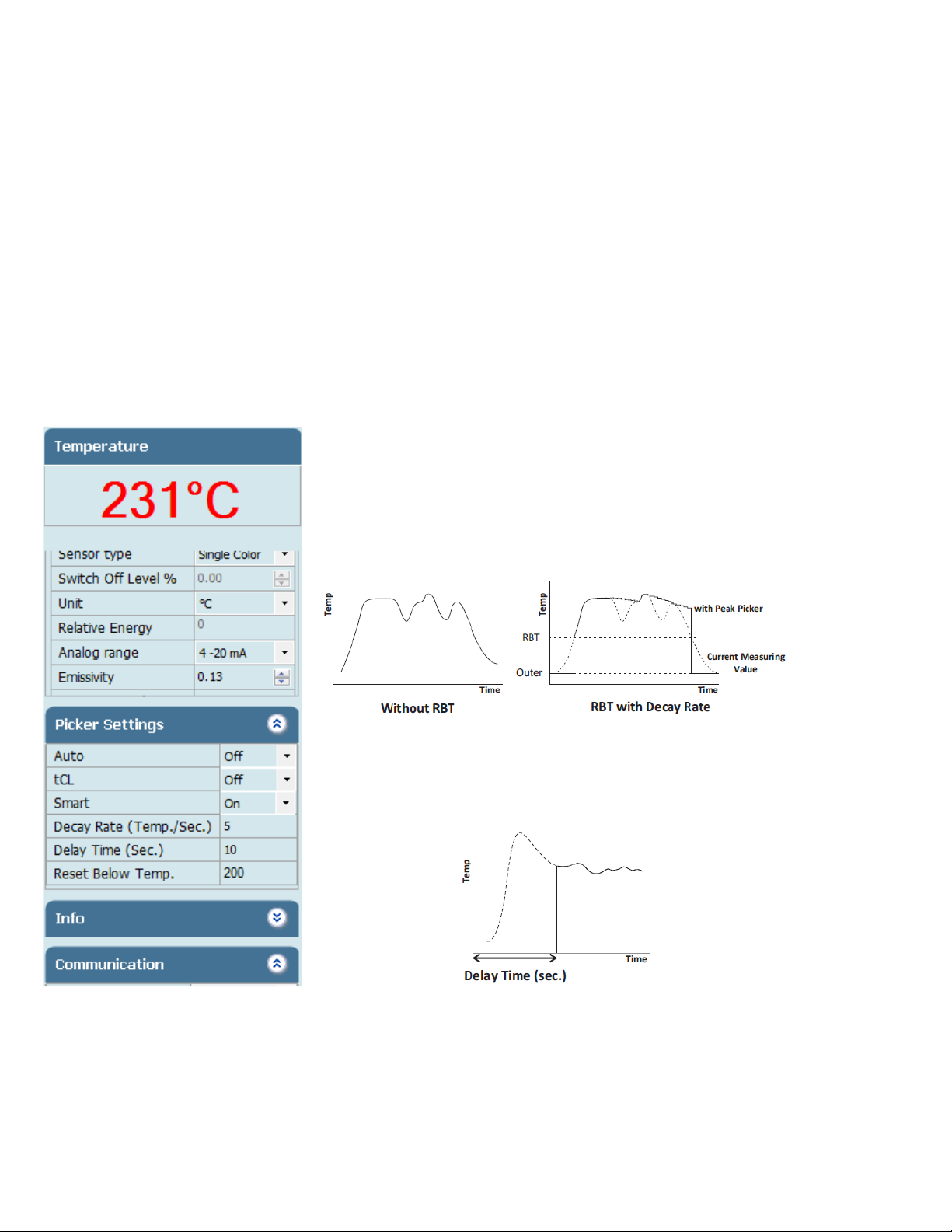
(G3) Smart If the smart picker is switched on, the highest last temperature value will always be
displayed and stored. This feature is particularly useful when object temperature is not uniform across
its dimension or the pyrometer is not constantly viewing an object to be measured.
Smart Picker Functions
Smart picker can be turn ON & OFF by using the software. When Peak picker is ON, the peak picker
menu is enabled for setting of the parameters like decay rate function, reset below temperature and
peak picker delay.
(I)Decay rate The Decay rate range is 0.00 to 166.66°C/sec. or 0.00 to
300°F/sec. depending upon °F/°C unit’s selection. The slowest Decay rate is
0 degrees per sec. This feature helps to eliminate erratic measurements
and allows the peaked value to decay down to lower process temperature
values as they occur. Decay rate is set to retain peak measured
temperature value and ignore momentary decreases in measured
temperature.
(ll)Delay Time This function set the delay time in sec. before peak picker
function starts. The delay time is selectable in the range 0.02 to 10.00 sec.
Zero (0) turns delay time OFF. This function is used to delay the start of
peaking action for upto 10 sec. following the detection of leading edge of a
new target.
(lll) Reset Below Temperature(RBT) The user can set RBT within the limit of pyrometer sub range. This
function setsthe temperature above which peak picker action starts. When the target temperature
matches or is below theselected value, the sensor indicates temperature without picking action.
Page 19
Page | 19
CONFIDENTIAL
(H)Relative energy(for two color pyrometer) The relative energy shows a signal weakening which can
be caused by contaminations of the optics or a viewing window or by dust in the field of view or a too
small measuring object. Relative energy shows the measured intensity compared to the intensity, a
black body radiation source would have at a determined ratio temperature of the pyrometer.
(I)Analog Range User can select the analog range from the option 4-20mA, 0-20 mA, 0-10V and J & K
type thermocouple.
(J)Comm. Mode User can select the communication mode as per requirement [RS-232 / RS-485].
Note: For connection diagram from RS-232 to RS-485 & RS-485 to RS-232 Refer Page No:-6
To view parameters of multiple devices select the pyrometer name from the drop down list that appears
at the top of the screen.
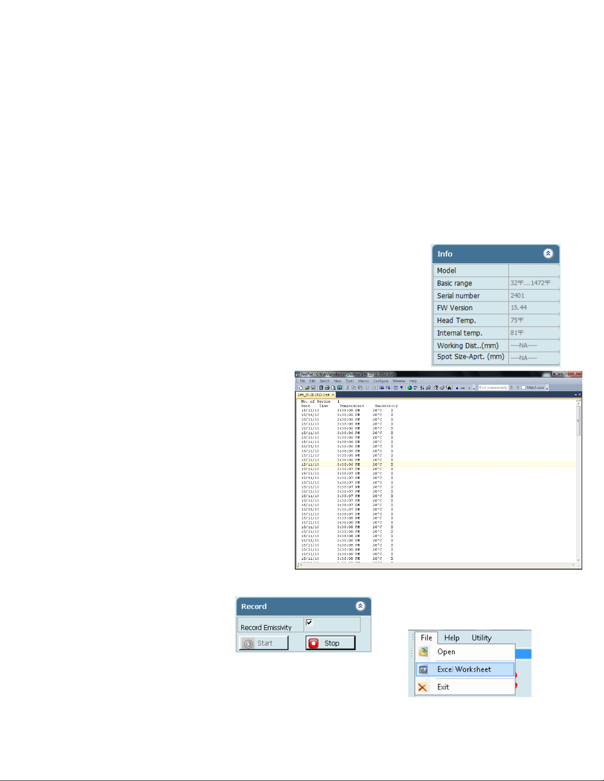
7.2.4 Device information
Pyrometer specific information will be displayed in the Info Panel
This screen shows the Model, basic range, serial number, version, Head
temperature, internal temperature, working distance, spot size aperture.
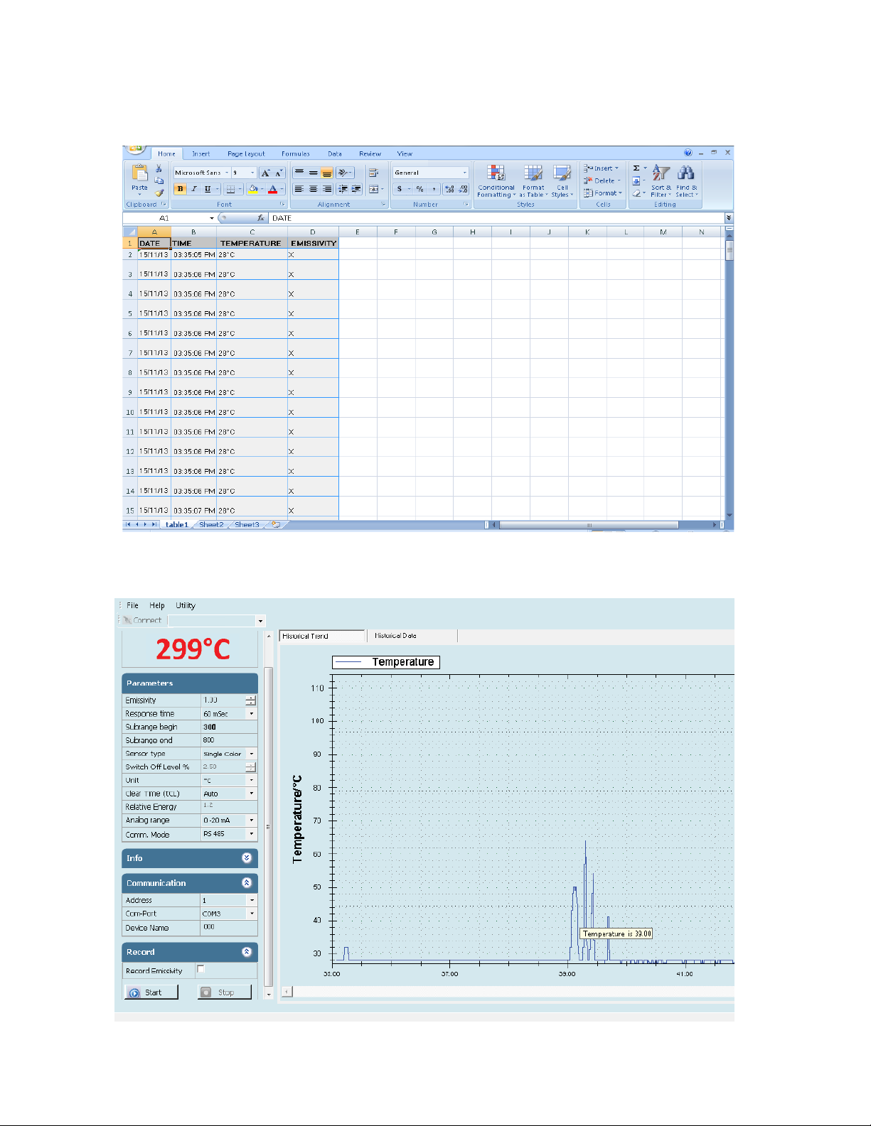
7.2.5 Record
Record is for continuous data logging. It records
the measured temperature, emissivity with
current date & time. To start data logging click
on start button. If user wants to record
emissivity, click on record emissivity button.
After Clicking Start button window appears
where user can specify the file name & location.
Record will be saved as .txt format and the
name of file will be user define.
Set minimum record time 1 Sec.
To record emissivity, click on Record Emissivity button.
If user wants file in Spreadsheet format, user can export notepad(.txt file)
by choosing Excel Spreadsheet in file menu. To export excel file, "Stop"
recording and then select "Excel Worksheet" in file menu so all recorded
data of .txt file will be exported to excel file.
Page 20
Page | 20
CONFIDENTIAL
File will be stored in .xls format named as “export”. This “export.xls” file will be saved where the
software is installed.
To see previous record open the file by clicking on menu File -> open.
Screen containing historical trend & historical data will appear.
Page 21
Page | 21
CONFIDENTIAL
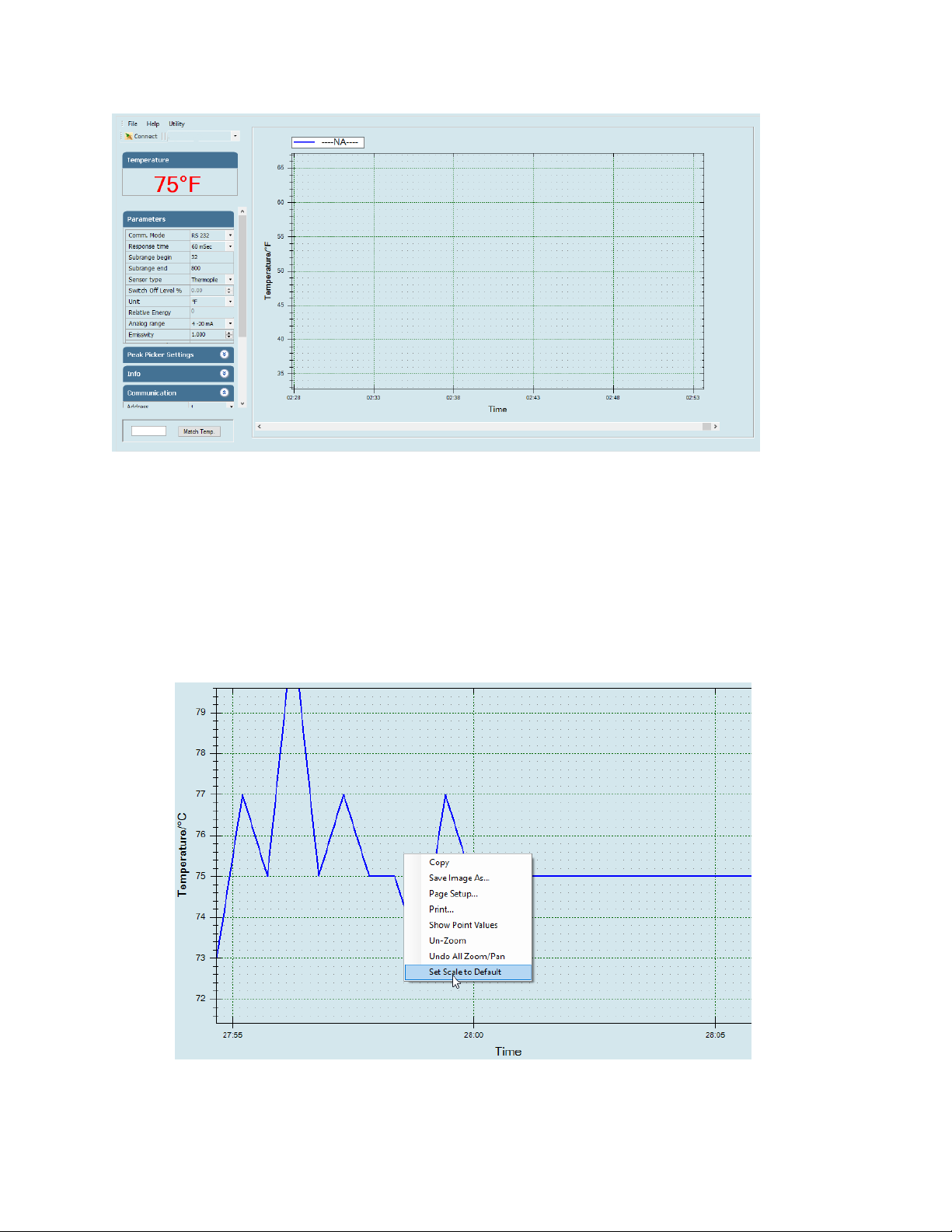
Temperature graph of connected pyrometer is displayed on right side of the screen. This shows the
measured temperature corresponding to the time.
Note:
After connecting the pyrometer right click on the graph screen and choose "Set to default" option from
pop-up menu.
Page 22
Page | 22
CONFIDENTIAL
Chapter – 8
Calculate Spot Size
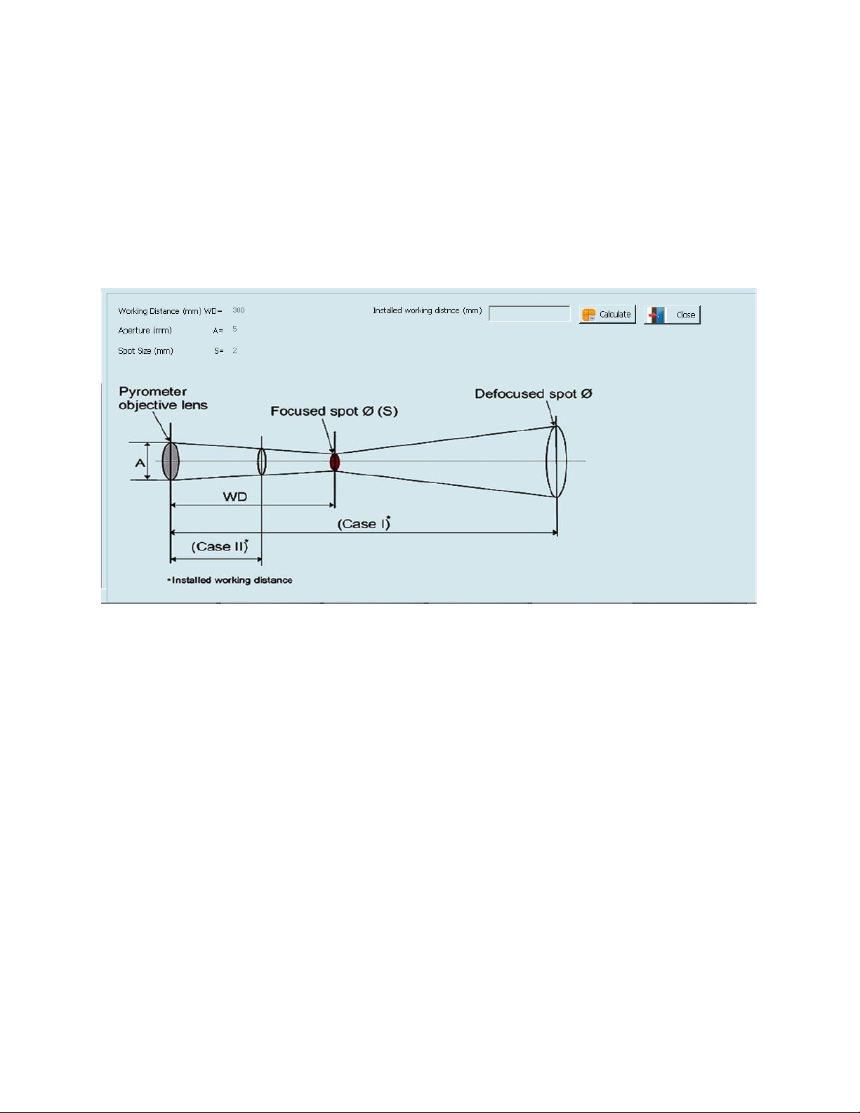
To calculate Spot Size click on Utility -> Calculate Spot Size
This option is used to calculate the spot size at installed working distance of the Pyrometer. When you
click on calculate spot size the new window will open.
WD = Manufactured working distance in (mm).
A = It shows the value of lens opening (Aperture in mm)
S = Manufactured spot size of the pyrometer (mm)
User has to enter the value of WD, A, S, of the installed pyrometer (These values are given in section –
2.3). Now, putting the value of “Installed working distance” it will show the value of “Installed spot size”.
Information
Maintenance
The pyrometer has no internal parts, which have to be cleaned. The lens can be cleaned with
compressed air, which is dry and free of oil. If the protection glass requires more thorough cleaning, use
a soft, dry cloth such as that used to clean camera lenses.
Packing instructions
To transport or store the instrument, please use the original box or a box padded with sufficient
shock absorbing material. For storage in humid areas or shipment overseas, the device should be placed
in welded foil (ideally along with silicone gel) to protect it from humidity.
 Loading...