

Page 1
MINI ADJUSTABLE STATUS
SWITCH SERIES
Installation & Operation Instructions
A/MCS-A, A/MSCS-A
Phone: 1-888-967-5224
Website: workaci.com
PRECAUTIONS
• This product is not intended to be used for
Life or Safety applications.
• This product is not intended for use in any
hazardous or classied locations.
HIGH VOLTAGE
• Disconnect and lock out all power sources
before installation as severe injury or death
may result from electrical shock due to
contact with high voltage wires.
GENERAL INFORMATION
The Miniature Adjustable Current switches are
designed for use in any AC current monitoring
application in which you are looking for an adjustable
current switch to monitor normal operating conditions,
equipment failure or preventative maintenance
scheduling for a particular piece of equipment. The
adjustable current switches should be installed on the
line side of the power to the motor, pump, compressor
or other equipment. The adjustable current status
switches can also be used to determine the run time of
your equipment where you want to know when your
piece of equipment runs and for how long it runs when
logging the contact closures on your building
management system or PLC.
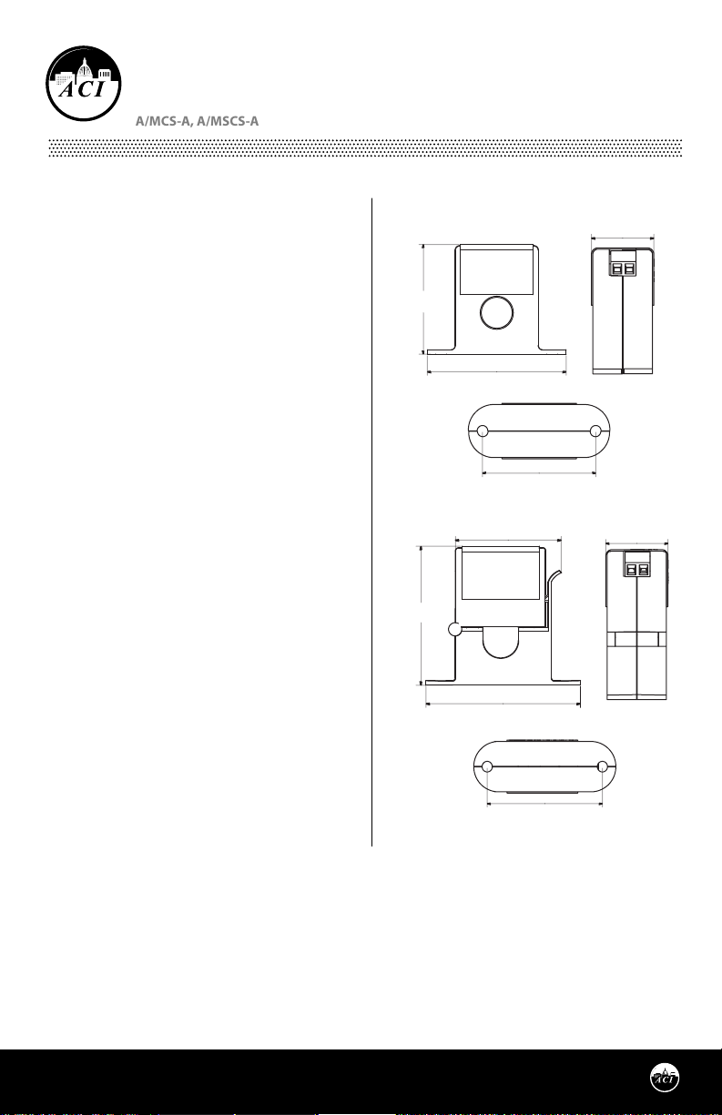
FIGURE 1: DIMENSIONS
Solid-Core
1.99”
(50.48mm)
2.51” (63.82mm)
2.00” (50.80mm)
Split-Core
1.82” (46.14mm)
2.38”
(60.49mm)
2.65” (67.19mm)
0.99”
(25.06mm)
0.99”
(25.06mm)
MOUNTING INSTRUCTIONS
Make sure that all installations are in compliance with
all national and local electrical codes. Only qualied
individuals that are familiar with codes, standards,
and proper safety procedures for high-voltage
installations should attempt installation. The current switches will not require external power, since the power
for the current switch is induced from the conductor being monitored.
The A/MCS-A and A/MSCS-A Current Switches should be used on Insulated Conductors Only! The current
switch may be mounted in any position using the (2) #8 x 3/4” Tek screws and the mounting holes in the base
(see Figure 2 (p.2)). Leave a minimum distance of 1” (3 cm) between the current switch and any other magnetic
devices such as contactors and transformers.
Page 1
Automation Components, Inc.
2305 Pleasant View Road | Middleton, WI 53562
Phone: 1-888-967-5224 | Website: workaci.com
2.15” (54.49mm)
Version: 8.0
I0000558
Page 2
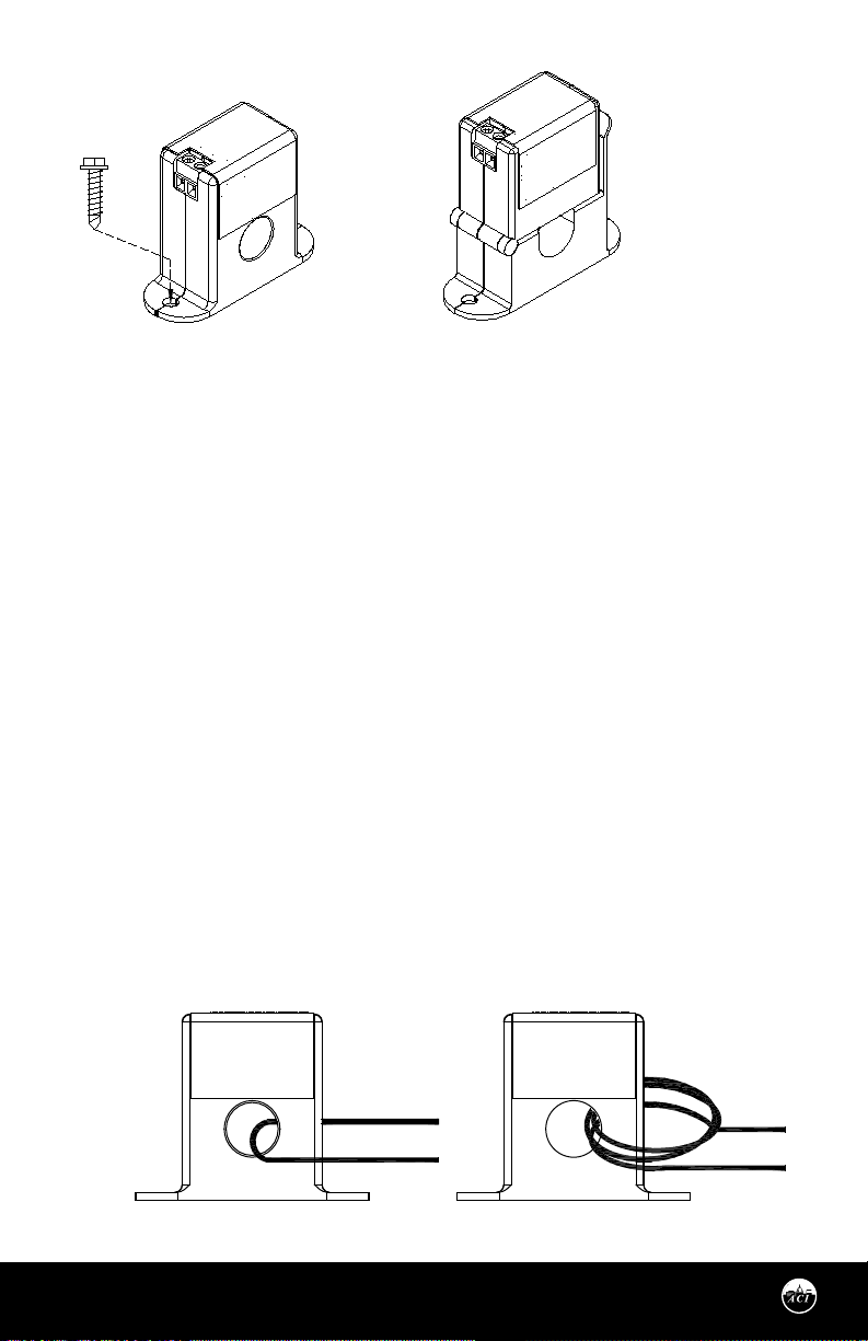
FIGURE 2: MOUNTING
#8 x 3/4" Tek Screw
(Qty. 2/Unit)
WIRING INSTRUCTIONS
ACI recommends the use of a two conductor 16 to 22 AWG shielded cable or twisted pair copper wire only
for all current switch applications. A maximum wire length of less than 30 meters (98.4 feet) should be
used between the A/MCS-A and A/MSCS-A current switches and the Building Management System or
controller.
Note: When using a shielded cable, be sure to connect only (1) end of the shield to ground at the
controller.
Connecting both ends of the shield to ground may cause a ground loop. When removing the shield from
the sensor end, make sure to properly trim the shield so as to prevent any chance of shorting. The current
switch output terminals represent a solid-state switch for controlling both AC and DC loads and is not
polarity sensitive. The recommended torque to be used on the terminal block connections is 0.67 Nm or
5.93 in-lbs. The aperture (hole) size of the current switch is 0.53” (1.35 cm) and will accept a 1 AWG
maximum wire diameter.
For applications in which the normal operating current is below the 0.20 Amps (A/MCS-A) or 0.55 Amps
(A/MSCS-A) trip point (See Figure 3 below), the conductor being monitored may be looped through the
sensor 4 times giving you a total operating current of 4X the original current.
Example: A small fan operating at 0.2A should be wrapped through the sensor 4 times to give you a total
operating current of 0.8Amps owing through the A/MCS-A or A/MSCS-A.
FIGURE 3: WIRES THROUGH SENSORS
Automation Components, Inc.
2305 Pleasant View Road | Middleton, WI 53562
Phone: 1-888-967-5224 | Website: workaci.com
ONE LOOP FOUR LOOPS
Page 2
Version: 8.0
I0000558
Page 3
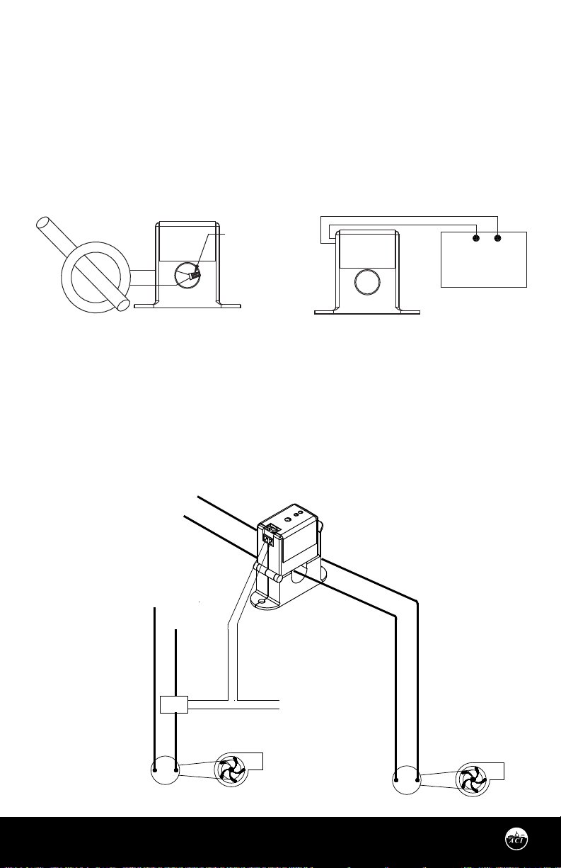
For applications in which the normal operating current is greater than 150 Amps or for conductor diameters larger than 0.530” (1.35 cm) in diameter, an external 5 Amp Current Transformer must be used as
shown in Figure 4 below.
Remember that the secondary of the 5A CT must be shorted together before the power may be
turned onto the monitored device.
Example: For currents up to 600 Amps (and not below 70 Amps (A/MCS-A) or 95 Amps (A/MSCS-A), where
Current Transformer (C.T.) secondary falls below 1 Amp use a 600:5 ratio C.T. as shown in Figure 4.
FIGURE 4: CURRENT TRANSFORMER FIGURE 5: DIGITAL CIRCUIT
Insulated
600:5 Ratio 5A C.T.
Conductor
Wire
Nut
Digital Input #1
Building Management
System
APPLICATION EXAMPLES
See Figure 5 (p.3) and Figure 6 (p.3) for two dierent current switch applications. Figure 5 (p.3) is showing
the use of the Mini Go/No Go Current Switch as a Digital Input to your BAS/PLC Controller. Figure 6 (p.3)
shows a Mini Go/No/Go Current Switch in conjunction with a Contactor to control an exhaust fan.
Note: The ACI Mini Adjustable Go/No Go Current switches(MCS-A & MSCS-A Series) are only rated at 1.0A
Continuous @ 36 VAC/VDC. These switches must use an additional Contactor if controlling motor/fans.
FIGURE 6: MOTOR/FAN CONTROL
120 VOLT HOT
NEUTRAL
120 VOLT HOT
RELAY
MOTOR
Automation Components, Inc.
2305 Pleasant View Road | Middleton, WI 53562
Phone: 1-888-967-5224 | Website: workaci.com
NEUTRAL
EXHAUST FAN
ACI SPLIT-CORE SWITCH
24 VAC HOT
NEUTRAL
RANGE HOOD FAN
MOTOR
Page 3
Version: 8.0
I0000558
Page 4
CALIBRATION OF ADJUSTABLE TRIP POINT
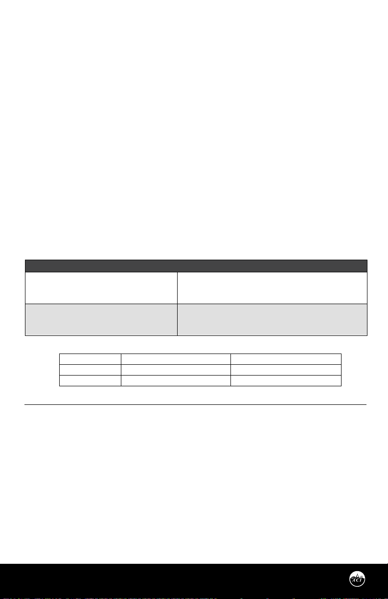
ACI Model #
Resistance if switch open
Resistance if switch closed
A/MCS-A
Greater than 1 Meg ohms
Approximately 0.2 ohms
A/MSCS-A
Greater than 1 Meg ohms
Approximately 0.2 ohms
The adjustable current switch has an operating range of 0-150 Amps. Do not exceed! The adjustable current
switch comes with its fteen-turn adjustment potentiometer set to the 100 Amp trip point position. The
adjustable current switch can be used to monitor Under Load, Normal Load, and Over Load conditions,
depending on how it’s set. The procedure below is for the Normal load condition for part numbers A/MCS-A &
A/MSCS-A.
NORMAL LOADS
With current owing through the aperture of the A/MCS-A and A/MSCS-A current switches, rst verify that
the Blue LED is on. If the Blue LED is on, now slowly adjust the potentiometer clockwise until the Red LED
just turns on and stop immediately. This will set the trip point at your normal operating load current.
If the RED LED is on after initial power up, this means that you will need to slowly adjust the potentiometer
counter-clockwise until the Blue LED turns on and then slowly adjust the potentiometer clockwise until the
Red LED just turns on and stop immediately. The adjustable current switch is now tripped. Now verify the
output with an Ohmmeter to verify that the contacts of the switch are approximately 0.200 Ohms. The
adjustable current switch Hysteresis (Dead Band) is typically 10% of the trip point.
Clockwise = Decrease Trip Point
Counter-clockwise = Increase Trip Point
TROUBLESHOOTING
PROBLEM
Current switch didn’t activate (Test #1)
Current switch didn’t activate (Test #2)
SOLUTION(S)
Disconnect the wires from the current switch output. Measure the resistance
across the contacts with an Ohmmeter. See Standard Ordering Table (p.5) for
the actual resistance readings for an open or closed switch reading.
Verify that the current owing in the conductor being monitored is above
the xed trip point as listed in the operating specications. If the sensor is
monitoring less than the xed trip point, see Figure 3.
WARRANTY
The ACI Current Switch Series are covered by ACI’s Five (5) Year Limited Warranty, which is located in the front of
ACI’S SENSORS & TRANSMITTERS CATALOG or can be found on ACI’s website: www.workaci.com.
W.E.E.E. DIRECTIVE
At the end of their useful life the packaging and product should be disposed of via a suitable recycling
centre. Do not dispose of with household waste. Do not burn.
Page 4
Automation Components, Inc.
2305 Pleasant View Road | Middleton, WI 53562
Phone: 1-888-967-5224 | Website: workaci.com
Version: 8.0
I0000558
Page 5
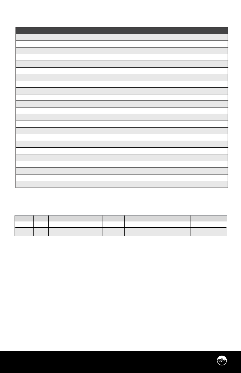
PRODUCT SPECIFICATIONS
SENSOR NON-SPECIFIC INFORMATION
Monitored Current Type:
Maximum AC Voltage:
Operating Frequency Range:
Core Style:
Sensor Power:
Amperage Range:
Isolation Voltage:
Trip Point Style | Trip Point:
Hysteresis:
Contact Type:
Contact Rating:
Contact “On” Resistance | “O” Resistance:
Response Time:
Status LED Indication:
Aperture Size:
Operating Temperature Range:
Operating Humidity Range:
Wiring Connections:
Wire Size:
Terminal Block Torque Rating:
Minimum Mounting Distance¹:
Pollution Degree:
Environmental:
Note¹: The LED should not be used to determine if current is present. At low currents the LED may not be visible.
AC Current
600 VAC
50/60 kHz
Solid-Core and Split-Core Versions available (See Ordering Grid)
Induced from the Monitored Conductor (Insulated Conductors only)
See Ordering Grid
2200 VAC
Adjustable Trip Point | See Ordering Grid
10% Trip Point, typical
Normally-Open “N/O”
1A Continuous @ 36 VAC/VDC
< 0.5 Ohms (tripped) | > 1 Meg Ohms (Open)
A/MCS-A:
< 90 mS typical |
Red LED (Current above trip point) | Blue LED (Current below trip point)
0.53” (13.46 mm)
-22 to 140ºF (-30 to 60ºC)
0 to 95%, non-condensing
2 Position Screw Terminal Block (Not Polarity Sensitive)
16 to 22 AWG (1.31 mm to 0.33 mm) Copper Wires only
4.43 to 5.31 in-lbs. (0.5 to 0.6 Nm)
1” (2.6 cm) between current switch (Relays, Contactors, Transformers)
2
Indoor
A/MSCS-A:
< 45 mS typical
STANDARD ORDERING
Trip Point Type
Model #
A/MCS-A
A/MSCS-A
Automation Components, Inc.
2305 Pleasant View Road | Middleton, WI 53562
Phone: 1-888-967-5224 | Website: workaci.com
Item #
117854
117855
Adjustable
Adjustable
Solid-Core•Split-Core•Amp Range
N/O
•
•
Page 5
0.32 to 150A
0.70 to 150A
Amp Range
0.32 to 150A
0.70 to 150A
Contact Rating
1A @ 36 VAC/VDC
1A @ 36 VAC/VDC
Version: 8.0
I0000558
Page 6
NOTES
Page 6
Automation Components, Inc.
2305 Pleasant View Road | Middleton, WI 53562
Phone: 1-888-967-5224 | Website: workaci.com
Version: 8.0
I0000558
Page 7
NOTES
Page 7
Automation Components, Inc.
2305 Pleasant View Road | Middleton, WI 53562
Phone: 1-888-967-5224 | Website: workaci.com
Version: 8.0
I0000558
Page 8
Automation Components, Inc.
2305 Pleasant View Road
Middleton, WI 53562
Phone: 1-888-967-5224
Website: workaci.com
Page 8
Automation Components, Inc.
2305 Pleasant View Road | Middleton, WI 53562
Phone: 1-888-967-5224 | Website: workaci.com
Version: 8.0
I0000558
 Loading...