

Page 1

by
ALTA Wireless Temperature Sensor
User Guide
Page 2
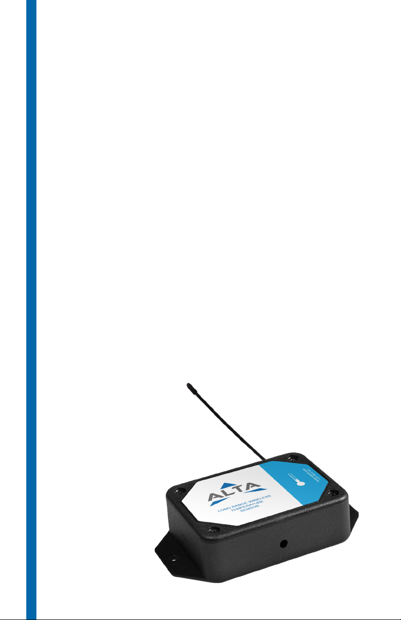
Table of Contents
I. ABOUT THE WIRELESS TEMPERATURE SENSOR 1
ALTA WIRELESS TEMPERATURE SENSOR FEATURES 1
EXAMPLE APPLICATIONS 1
II. SENSOR SECURITY
SENSOR COMMUNICATION SECURITY
DATA SECURITY ON THE GATEWAY
iMONNIT SECURITY 2
III. REGISTRATION
REGISTERING A TEMPERATURE SENSOR
IV. SETTING UP THE TEMPERATURE SENSOR
INSTALLING BATTERIES
MOUNTING THE SENSOR 5
ANTENNA ORIENTATION 6
V. SENSOR OVERVIEW
MENU SYSTEM
SUPPORT
WARRANTY INFORMATION
CERTIFICATIONS 16
2
2
2
3
3
4
4
7
7
14
14
Page 3

I. ABOUT THE WIRELESSS TEMPERATURE SENSOR
The ALTA Wireless Temperature Sensor measures the ambient thermal conditions of your
environment. These sensors accurately monitor temperature changes in your physical
location. Settings including notications, alerts, reports, and maps are customizable in the
online interface of iMonnit. The temperature sensor is built to be out of the box and running
in minutes.
Industry leading 25 month NIST certied product included on leaded temperature sensors.
ALTA WIRELESS TEMPERATURE SENSOR FEATURES
• Wireless range of 1,200+ feet through 12+ walls *
• Frequency-Hopping Spread Spectrum (FHSS)
• Interference immunity
• Power management for longer battery life **(12+ years on AA batteries)
• Encrypt-RF® Security (Die-Hellman Key Exchange + AES-128 CBC for sensor
data messages)
• Onboard data memory stores up to hundreds of readings per sensor:
- 10-minute heartbeats = 3.5 days
- 2-hour heartbeats = 42 days
• Over-the-air updates (future proof)
• Free iMonnit basic online wireless sensor monitoring and notication system to
congure sensors, view data and set alerts via SMS text and email
* Actual range may vary depending on environment.
** Battery life is determined by sensor reporting frequency and other variables. Other power options are also
available.
EXAMPLE APPLICATIONS
• Ambient temperature monitoring
• Environmental monitoring
• Smart machines & smart structures
• HVAC operation & testing
• Data center monitoring
• Many additional applications
PAGE 1
Page 4

II. SENSOR SECURITY
The ALTA Wireless Temperature Sensor has been designed and built to securely manage
data from sensors monitoring your environment and equipment. Hacking from botnets are
in the headlines, Monnit Corporation has taken extreme measures to ensure your data
security is handled with the utmost care and attention to detail. The same methods utilized
by nancial institutions to transmit data are also used in Monnit security infrastructure.
Security features of the gateway include tamper proof network interfaces, data encryption,
and bank-grade security.
Monnit’s proprietary sensor protocol uses low transmit power and specialized radio
equipment to transmit application data. Wireless devices listening on open communication
protocols cannot eavesdrop on sensors. Packet level encryption and verication is key
to ensuring trac isn’t altered between sensors and gateways. Paired with best-in-class
range and power consumption protocol, all data is transmitted securely from your devices.
Thereby ensuring a smooth, worry-free, experience.
SENSOR COMMUNICATION SECURITY
Monnit sensor to gateway secure wireless tunnel is generated using ECDH-256 (Elliptic
Curve Die-Hellman) public key exchange to generate a unique symmetric key between
each pair of devices. Sensors and gateways use this link specic key to process packet
level data with hardware accelerated 128-bit AES encryption which minimizes power
consumption to provide industry best battery life. Thanks to this combination, Monnit
proudly oers robust bank-grade security at every level.
DATA SECURITY ON THE GATEWAY
The ALTA gateways are designed to prevent prying eyes from accessing the data that is
stored on the sensors. Gateways do not run on an o the shelf multi-function OS (operating
system). Instead they run a purpose specic real-time embedded state machine that cannot
be hacked to run malicious processes. There are also no active interface listeners that
can be used to gain access to the device over the network. The fortied gateway secures
your data from attackers and secures the gateway from becoming a relay for malicious
programs.
iMONNIT SECURITY
iMonnit is the online software and central hub for conguring your device settings. All
data is secured on dedicated servers operating Microsoft SQL Server. Access is granted
through the iMonnit user interface, or an Application Programming Interface (API)
safeguarded by 256-bit Transport Layer Security (TLS 1.2) encryption. TLS is blanket of
protection to encrypt all data exchanged between iMonnit and you. The same encryption
is available to you whether you are a Basic user of Premiere user of iMonnit. You can rest
assured that your data is safe with iMonnit.
PAGE 2
Page 5
III. REGISTRATION
If this is your rst time using the iMonnit online portal, you will need to create a new
account. If you have already created an account, start by logging in. For instructions on
how to register for an iMonnit account, please consult the iMonnit User Guide viewable at
monnit.com/support/documentation.
REGISTERING THE TEMPERATURE SENSOR
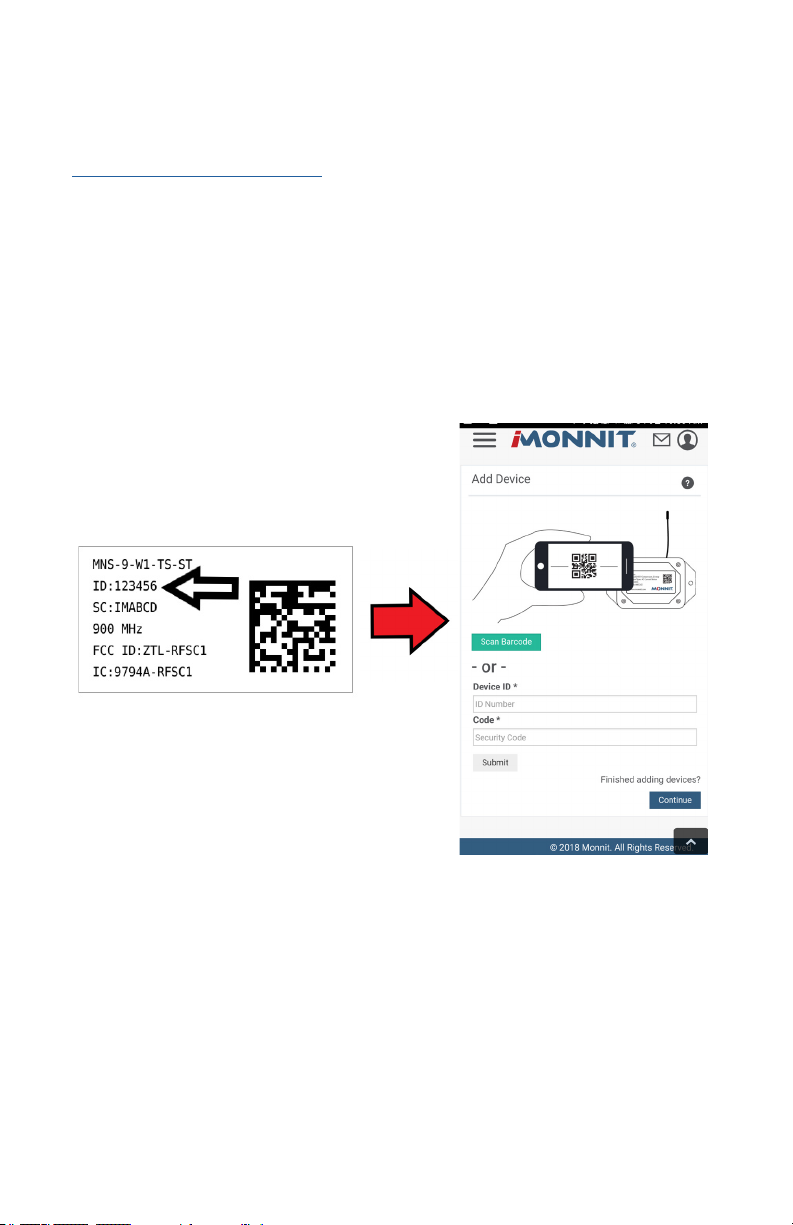
You will need to enter the Device ID and the Security Code from your Temperature Sensor
in the corresponding text boxes. Use the camera on your smartphone to scan the QR code
on your sensor and gateway. If you do not have a camera on your phone, or the system is
not accepting the QR code, you may enter the Device ID and Security Code manually.
• The Device ID is a unique number located on each device label.
• Next you’ll be asked to enter the Security Code (SC) on your device. A security
code will be all letters and must be entered in upper case, no numbers. It can also
be found on the barcode label of your gateway.
When completed, select the “Submit” button.
PAGE 3
Page 6
IV. SETTING UP YOUR TEMPERATURE SENSOR
Pull
(sensor away from base)
Pinch
(press in on the sides)
Press
(sensor back into base)
CR2032 BATTERY
+
_
CR2032 BATTERY
When you are nished adding the sensor to your account, the next step is to insert the
battery. The type of battery you use will depend on the category of your sensor. ALTA
Wireless Temperature Sensors will either be powered by commecial coin cell, AA, or an
industrial battery.
INSTALLING BATTERIES
ALTA commercial sensors are powered by AA or CR2032 coin cell batteries. Industrial sensors need a 3.6V Lithium battery supplied from Monnit or another industrial battery supplier.
Monnit encourages customers to recycle all old batteries.
Coin Cell
The lifespan of a standard CR2032 coin cell battery in an ALTA Temperature Sensor is 3+
years.
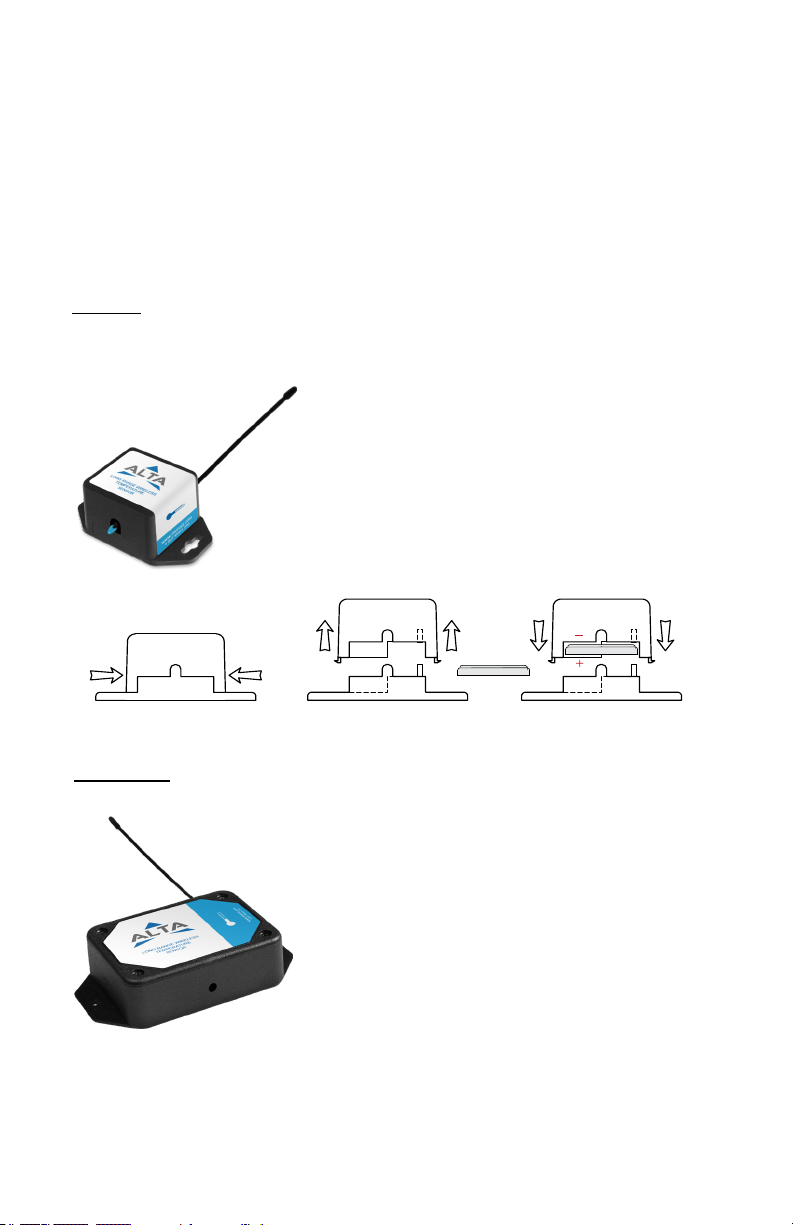
Install a coin cell battery by rst taking the sensor and
pinching the sides of the enclosure. Gently pull up the
enclosure, separating the sensor from its base. Then slide
a new CR2032 coin cell battery with the positive side
facing toward the base. Press the the enclosure back to
together; you’ll hear a small click.
Lastly, open iMonnit select Sensors from the navigation
menu. Verify that iMonnit is showing the sensor has a full
battery level.
AA Batteries
The standard version of this sensor is powered by two
replaceable 1.5 V AA sized batteries (included with
purchase). The typical battery life is 10 -12 years.
This sensor is also available with a line power option. The
line powered version of this sensor has a barrel power
connector allowing it to be powered by a standard 3.0–3.6
V power supply. The line powered version also uses two
standard 1.5 V AA batteries as backup for uninterrupted
operation in the event of line power outage.
Power options must be selected at time of purchase, as
the internal hardware of the sensor must be changed to
support the selected power requirements.
Place batteries in the device by rst taking the sensor and sliding the battery door
open.Insert fresh AA batteries in the carriage, then shut the battery door.
Complete the process by opening up iMonnit and selecting Sensors from the main
navigation menu. Verify that iMonnit is showing the sensor has a full battery level.
PAGE 4
Page 7
Industrial Batteries
3.6V Lithium batteries for the Industrial Wireless Temperature
Sensor is supplied by Monnit. The ALTA battery life for the
Industrial battery is 10 – 12 years.
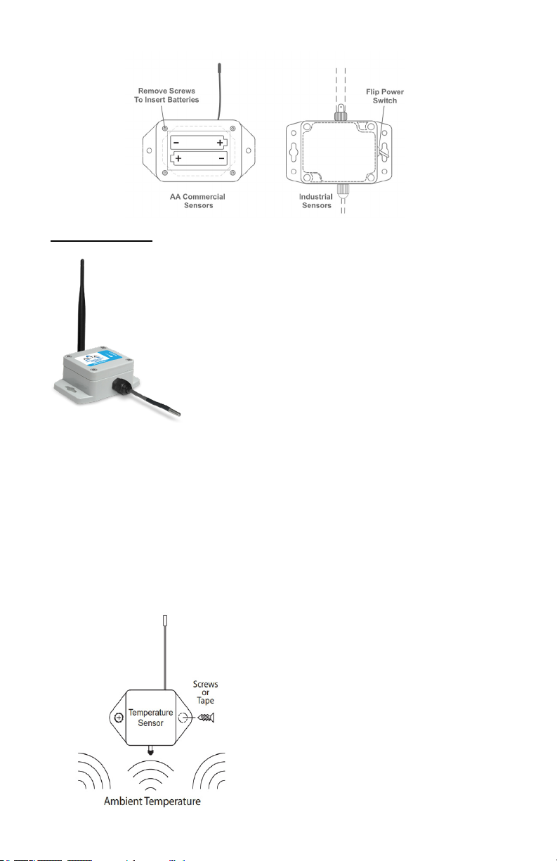
Install the battery by taking the sensor and unscrewing the
four screws at the corners. Tuck-in a fresh battery in the
carriage, then adjust clips to hold the battery in place.
Open iMonnit and select Sensors from the main navigation
menu. Verify that iMonnit is showing the sensor has a full
battery level. Replace the battery door by screwing in the
four corners.
In order for the sensor to function properly, you will need to attach the included antenna.
Simply screw the antenna onto the barrel connector on the top of the device. Make sure
to snug the antenna connection, but do not over tighten. When placing the sensor, make
sure to mount the sensor with the antenna oriented straight up (vertical) to ensure the best
wireless radio signal.
Since the electronics are sealed within the sensor housing, we have added an "On/O"
switch to the unit for your convenience. If you are not using the sensor, simply leave the
button in the o position to preserve battery life. If the sensor needs to be reset for any
reason, you can simply cycle the power by turning the switch to the "O" position and
waiting 30 seconds before powering back on.
MOUNTING THE SENSOR
Monnit wireless temperature sensors monitor the
ambient temperature around the sensor. Monnit
wireless sensors feature mounting anges and can
be attached to most surfaces using the included
mounting screws or double-sided tape.
PAGE 5
Page 8
ANTENNA ORIENTATION
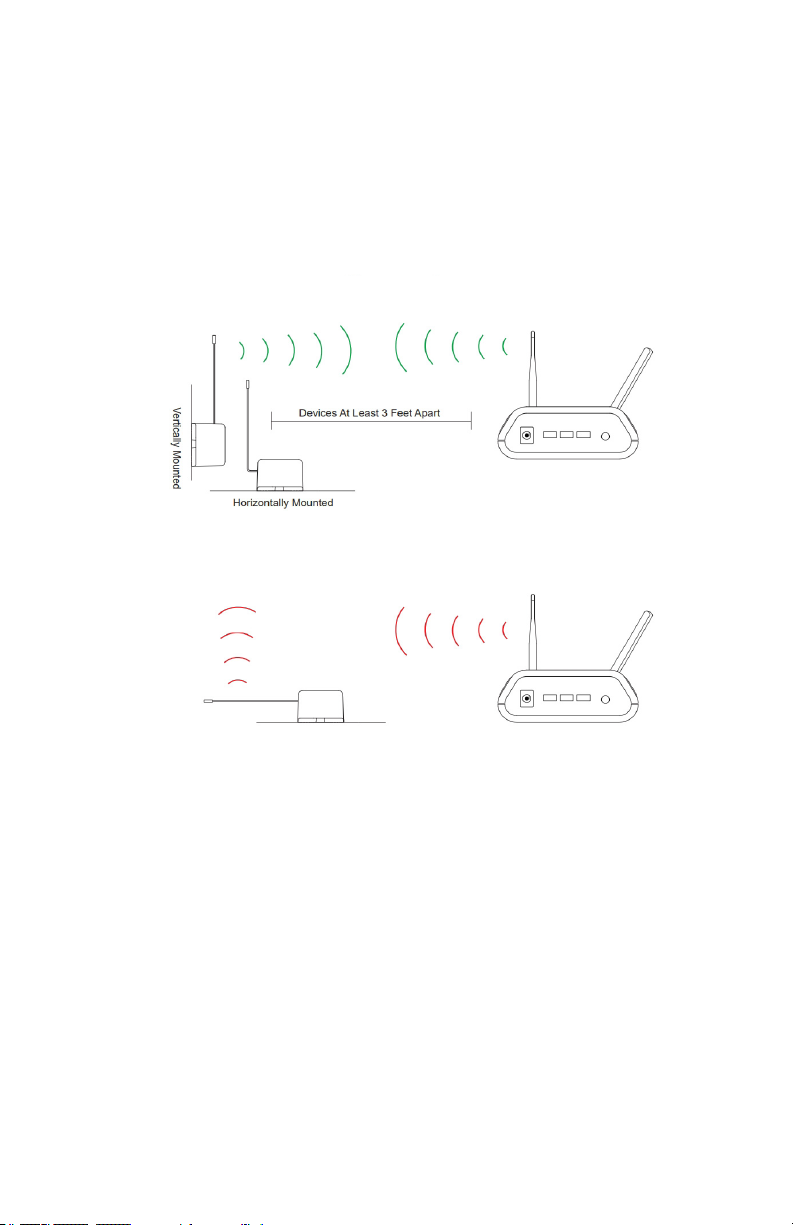
In order to get the best performance out of your ALTA Wireless Sensors, it is important to
note proper antenna orientation and sensor positioning. Antennas should all be oriented in
the same direction, pointing vertically from the sensor. If the sensor is mounted at on its
back on a horizontal surface, you should bend the antenna as close to the sensor housing
as possible giving you the most amount of antenna pointing vertical. You should make the
antenna wire as straight as possible, avoiding any kinks and curving of the wire. Sensors
must be at least 3 ft. away from other sensors and the wireless gateway to function.
More Signal
Less Signal
PAGE 6
Page 9
V. SENSOR OVERVIEW
Select Sensors from the main navigation menu on iMonnit to access the sensor overview
page and begin making adjustments to your Temperature Sensors.
MENU SYSTEM
Details - Displays a graph of recent sensor data.
History - List of all past heartbeats and readings.
Events - List of all events attached to this sensor.
Settings - Editable levels for your sensor.
Calibrate - Reset readings for your sensor.
Scale - Change the scale of readings for your sensor.
Directly under the tab bar is an overview of your sensor. This allows you to see the signal
strength and the battery level of the selected sensor.
• indicates the sensor is checking in and within user dened safe parameters.
•
indicates the sensor has met or exceeded a user dened threshold or triggered event.
indicates that no sensor readings are being recorded, rendering the sensor inactive.
•
Details View
The Details View will be the rst page you see upon selecting which sensor you would like
to modify.
PAGE 7
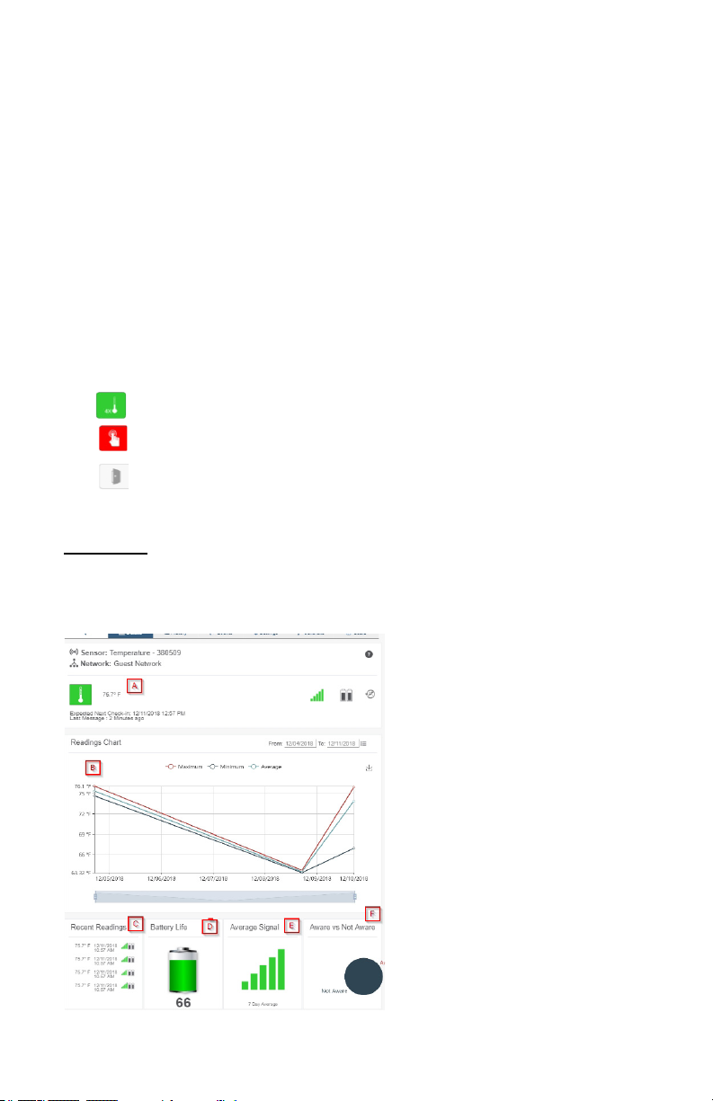
A. The sensor overview section
will be above every page. This will
consistently display the present
reading, signal strength, battery level,
and status.
B. This graph charts how the sensor
uctuates throughout a set date
range. To change the date range
displayed in the graph, navigate up to
the top of the Readings Chart section
on the right-hand corner to change
the from and/or to date.
C. The Recent Readings section
below the chart shows your most
recent data received by the sensor.
D. Battery Life displays the current
battery percentage remaining.
E. The Average Signal shows the
most common signal strength of your
sensor. Low signal strength could be
Page 10
a sign the placement of your sensor should be adjusted.
F. The pie chart in the Aware or Not Aware Section displays the percentage of aware states
your sensor has entered since activation.
History View
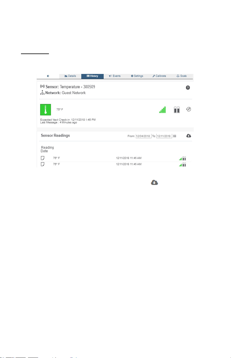
Selecting the “History” tab within the tab bar allows you to view the sensor’s data history as
time stamped data.
• On the far right of the sensor history data is a cloud icon. Selecting this icon will
export an excel le for your sensor into your download folder.
Note: Make sure you have the date range for the data you need input in the “From” and “To” text boxes. This will be
the most recent week by default. Only the rst 2,500 entries in the selected date range will be exported.
The data le will have the following elds:
MessageID: Unique identier of the message in our database.
SensorID: If multiple sensors are exported you can distinguish which reading was from
which using this number even if the names for some reason are the same.
Sensor Name: The name you have given the sensor.
Date: The date the message was transmitted from the sensor.
Value: Data presented with transformations applied but without additional labels.
Formatted Value: Data transformed and presented as it is shown in the monitoring portal.
Battery: Estimated life remaining of the battery.
Raw Data: Raw data as it is stored from the sensor.
Sensor State: Binary eld represented as an integer containing information about the state
or the sensor when the message was transmitted. (See “Sensor State Explained” below).
Gateway ID: The Identier of the gateway that relayed the data from the sensor.
Alert Sent: Boolean indicating if this reading triggered a notication to be sent from the
system.
Signal Strength: Strength of communication signal between the sensor and the gateway,
shown as percentage value.
PAGE 8
Page 11

Voltage: Actual voltage measured at the sensor battery used to calculate battery percentage,
similar to Received Signal you can use one or the other or both if they help you.
State
The integer presented here is generated from a single byte of stored data. A byte consists
of 8 bits of data that we read as Boolean (True (1)/False (0)) elds.
Using a temperature sensor as an example.
If the sensor is using factory calibrations the Calibrate Active eld is set True (1) so the bit
values are 00010000 and it is represented as 16.
If the sensor is outside the Min or Max threshold, the Aware State is set True (1) so the bit
values are 00000010 and it is represented as 2.
If the customer has calibrated the sensor this eld the Calibrate Active eld is set False
(0) AND the sensor is operating inside the Min and Max Thresholds, the bits look like
00000000 this is represented as 0.
If the sensor is using factory calibrations and it is outside the threshold the bit values are
00010010 and it is represented as 18 (16 + 2 because both the bit in the 16 value is set
and the bit in the 2 value is set).
Note: These two are the only bits that typically observed outside of our testing procedures.
PAGE 9
Page 12
Settings View
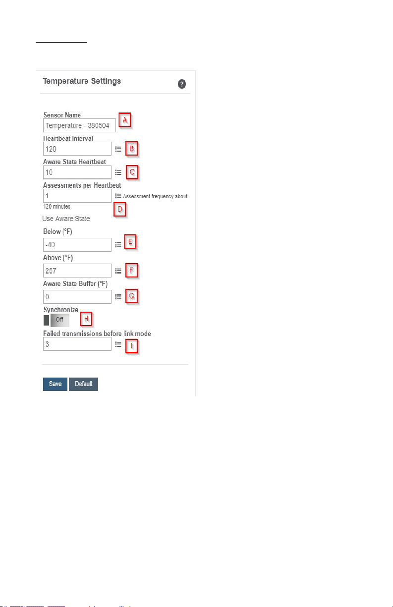
To edit the operational settings for a sensor, choose the “Sensor” option in the main
navigation menu then select the “Settings” tab to access the conguration page.
A. Sensor Name is a unique name you
give the sensor to easily identify it in a list
and in any notications.
B. The Heartbeat Interval is how
often the sensor communicates with the
gateway if no activity is recorded.
C. Aware State Heartbeat is how
often the sensor communicates with the
gateway while in an Aware State.
D. Assessments per Heartbeat is how
many times between heartbeats a sensor
will check its measurements against its
thresholds to determine whether it will
enter an Aware State.
E. Below is the minimum reading the
sensor should record before entering an
Aware State.
F. Above is the maximum reading the
sensor should record before entering an
Aware State.
G. The Aware State Buer is a buer
to prevent the sensor from bouncing
between Standard Operation and Aware
State when the assessments are very
close to a threshold. For example, if a
Maximum Threshold is set to 90° and the
buer is 1°, then once the sensor takes
an assessment of 90.1° it will remain in an
Aware State until dropping to 89.0°.
Similarly at the Minimum Threshold the temperature will have to rise a degree above the
threshold to return to Standard Operation.
H. In small sensor networks the sensors can be set to synchronize their communications.
The default setting o allows the sensors to randomize their communications therefore
maximizing communication robustness. Setting this will synchronize the communication of
the sensors.
I. Failed transmissions before link mode is the number of transmissions the sensor
sends without response from a gateway before it goes to battery saving link mode. In link
mode, the sensor will scan for a new gateway and if not found will enter battery saving
sleep mode for up to 60 minutes before trying to scan again. A lower number will allow
sensors to nd new gateways with fewer missed readings. Higher numbers will enable the
sensor to remain with its current gateway in a noisy RF environment better. (Zero will cause
the sensor to never join another gateway, to nd a new gateway the battery will have to be
cycled out of the sensor.)
PAGE 10
Page 13
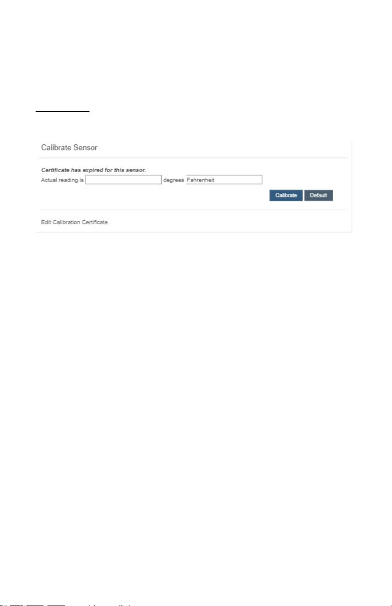
The default heartbeat interval is 120 minutes or two hours. It is recommended that you do
not lower your heartbeat level too much because it will drain the battery.
Finish by selecting the “Save” button.
Note: Be sure to select the “Save” button anytime you make a change to any of the sensor parameters. All
changes made to the sensor settings will be downloaded to the sensor on the next sensor heartbeat (checkin). Once a change has been made and saved, you will not be able to edit that sensor’s conguration again
until it has downloaded the new setting.
Calibrate View
If a sensor type has readings that need to be reset, the “Calibrate” tab will be available for
selection in the sensor tab bar.
To calibrate a sensor, you will want to ensure that the environment of the sensor and other
calibration device is stable. Note the “Expected Next Check-in” time for the sensor you
are calibrating and take a reading from your calibration device a few minutes prior to the
sensors next check-in.
Enter the actual (accurate) reading from the calibration device into the text eld. If you need
to change the unit of measurement you can do that here.
Press “Calibrate”.
To ensure that the calibration command is received prior to the sensors next check-in,
press the control button on the back of the gateway, once, to force communication (Cellular
and Ethernet gateways).
After pressing the "Calibrate" button and choosing the gateway button, the server will send
the command to calibrate the specied sensor to the gateway. When the sensor checks-in,
it will send the pre-calibration reading to the gateway, then receive the calibration command
and update it’s conguration. When the process is completed, it will send a “Calibration
Successful” message. The server will display the sensor’s last pre-calibrated reading for
this check-in, then all future readings from the sensor will be based on the new calibration
setting.
It is important to note that after calibrating the sensor, the sensor reading returned to the
server is based on pre-calibration settings. The new calibration settings will take eect on
the next sensor heartbeat.
Note: If you would like to send the changes to the sensor right away, please remove the battery(s) for a full 60
seconds, then re-insert the battery(s). This forces the communication from the sensor to the gateway and this the
message to make a change from the gateway back to the sensor. (If the sensors are industrial sensors, turn the
sensor o for a full minute, rather than removing the battery).
PAGE 11
Page 14
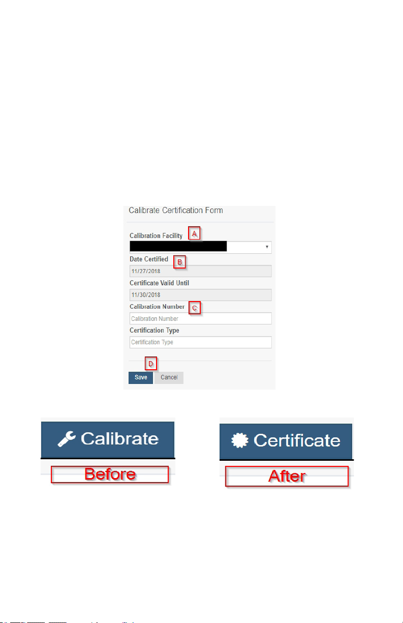
Creating a Calibration Certicate
Creating a sensor calibration certicate will mask the calibration tab from those who should
not have permissions to adjust these settings. Permissions for self-certifying a calibration
must be enabled in user permissions.
Directly below the calibrate button is the selection to "Create Calibration Certicate.
A. The Calibration Facility Field will be lled. Select the dropdown menu to change your
facility.
B. The date for "Certicate Valid Until" must be set one day in the future after the date
contained in the "Date Certied" eld.
C. "Calibration Number" and "Calibration Type" are unique values to your certicate.
D. Choose the "Save" button before moving on.
When the new certicate is accepted, the Calibration tab will change to a Certicate tab.
You will still be able to edit the certicate by choosing the Certicate Tab and navigating
down to "Edit Calibration Certicate."
The tab will revert back to "Calibrate" after the period for the certicate ends.
PAGE 12
Page 15
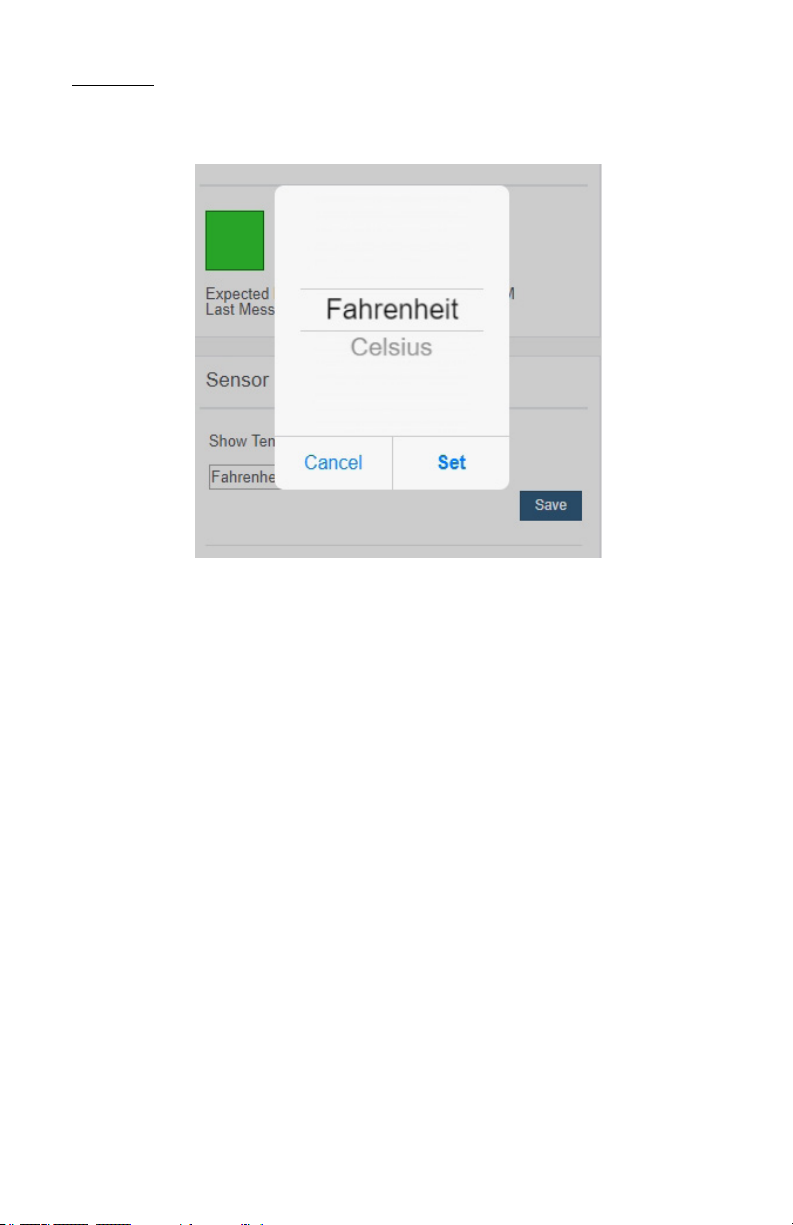
Scale View
If the sensor settings are inuenced by temperature, the scale option will be available in the
tab bar. To change the temperature unit of measurement from Fahrenheit to Celsius or vice
versa, select the Scale tab.
Choose the text box to trigger a pop-up window allowing you to change the scale. Select
the scale you prefer and push “Set.”
Press the “Save” button to complete your adjustment.
PAGE 13
Page 16

SUPPORT
For technical support and troubleshooting tips please visit our support library online at
monnit.com/support/. If you are unable to solve your issue using our online support, email
Monnit support at [email protected] with your contact information and a description of
the problem, and a support representative will call you within one business day.
For error reporting, please email a full description of the error to [email protected].
WARRANTY INFORMATION
(a) Monnit warrants that Monnit-branded products (Products) will be free from defects
in materials and workmanship for a period of one (1) year from the date of delivery with
respect to hardware and will materially conform to their published specications for a period
of one (1) year with respect to software. Monnit may resell sensors manufactured by other
entities and are subject to their individual warranties; Monnit will not enhance or extend
those warranties. Monnit does not warrant that the software or any portion thereof is error
free. Monnit will have no warranty obligation with respect to Products subjected to abuse,
misuse, negligence or accident. If any software or rmware incorporated in any Product
fails to conform to the warranty set forth in this Section, Monnit shall provide a bug x or
software patch correcting such non-conformance within a reasonable period after Monnit
receives from Customer (i) notice of such non-conformance, and (ii) sucient information
regarding such non-conformance so as to permit Monnit to create such bug x or software
patch. If any hardware component of any Product fails to conform to the warranty in this
Section, Monnit shall, at its option, refund the purchase price less any discounts, or repair
or replace nonconforming Products with conforming Products or Products having substantially identical form, t, and function and deliver the repaired or replacement Product to a
carrier for land shipment to customer within a reasonable period after Monnit receives from
Customer (i) notice of such non-conformance, and (ii) the non-conforming Product provided; however, if, in its opinion, Monnit cannot repair or replace on commercially reasonable
terms it may choose to refund the purchase price. Repair parts and replacement Products
may be reconditioned or new. All replacement Products and parts become the property of
Monnit. Repaired or replacement Products shall be subject to the warranty, if any remains,
originally applicable to the product repaired or replaced. Customer must obtain from Monnit
a Return Material Authorization Number (RMA) prior to returning any Products to Monnit.
Products returned under this Warranty must be unmodied.
Customer may return all Products for repair or replacement due to defects in original
materials and workmanship if Monnit is notied within one year of customer’s receipt of the
product. Monnit reserves the right to repair or replace Products at its own and complete discretion. Customer must obtain from Monnit a Return Material Authorization Number (RMA)
prior to returning any Products to Monnit. Products returned under this Warranty must be
unmodied and in original packaging. Monnit reserves the right to refuse warranty repairs
or replacements for any Products that are damaged or not in original form. For Products
outside the one year warranty period repair services are available at Monnit at standard
labor rates for a period of one year from the Customer’s original date of receipt.
(b) As a condition to Monnit’s obligations under the immediately preceding paragraphs,
Customer shall return Products to be examined and replaced to Monnit’s facilities, in
shipping cartons which clearly display a valid RMA number provided by Monnit. Customer
acknowledges that replacement Products may be repaired, refurbished or tested and found
to be complying. Customer shall bear the risk of loss for such return shipment and shall
bear all shipping costs. Monnit shall deliver replacements for Products determined by Mon-
nit to be properly returned, shall bear the risk of loss and such costs of shipment of repaired
Products or replacements, and shall credit Customer’s reasonable costs of shipping such
returned Products against future purchases.
PAGE 14
Page 17

(c) Monnit’s sole obligation under the warranty described or set forth here shall be to repair
or replace non-conforming products as set forth in the immediately preceding paragraph, or
to refund the documented purchase price for non-conforming Products to Customer. Mon-
nit’s warranty obligations shall run solely to Customer, and Monnit shall have no obligation
to customers of Customer or other users of the Products.
Limitation of Warranty and Remedies.
THE WARRANTY SET FORTH HEREIN IS THE ONLY WARRANTY APPLICABLE TO
PRODUCTS PURCHASED BY CUSTOMER. ALL OTHER WARRANTIES, EXPRESS
OR IMPLIED, INCLUDING BUT NOT LIMITED TO THE IMPLIED WARRANTIES OF
MERCHANTABILITY AND FITNESS FOR A PARTICULAR PURPOSE ARE EXPRESSLY
DISCLAIMED. MONNIT’S LIABIITY WHETHER IN CONTRACT, IN TORT, UNDER ANY
WARRANTY, IN NEGLIGENCE OR OTHERWISE SHALL NOT EXCEED THE PURCHASE
PRICE PAID BY CUSTOMER FOR THE PRODUCT. UNDER NO CIRCUMSTANCES
SHALL MONNIT BE LIABLE FOR SPECIAL, INDIRECT OR CONSEQUENTIAL DAMAGES. THE PRICE STATED FOR THE PRODUCTS IS A CONSIDERATION IN LIMITING
MONNIT’S LIABILITY. NO ACTION, REGARDLESS OF FORM, ARISING OUT OF THIS
AGREEMENT MAY BE BROUGHT BY CUSTOMER MORE THAN ONE YEAR AFTER
THE CAUSE OF ACTION HAS ACCRUED.
IN ADDITION TO THE WARRANTIES DISCLAIMED ABOVE, MONNIT SPECIFICALLY
DISCLAIMS ANY AND ALL LIABILITY AND WARRANTIES, IMPLIED OR EXPRESSED,
FOR USES REQUIRING FAIL-SAFE PERFORMANCE IN WHICH FAILURE OF A PROD-
UCT COULD LEAD TO DEATH, SERIOUS PERSONAL INJURY, OR SEVERE PHYSICAL
OR ENVIRONMENTAL DAMAGE SUCH AS, BUT NOT LIMITED TO, LIFE SUPPORT OR
MEDICAL DEVICES OR NUCLEAR APPLICATIONS. PRODUCTS ARE NOT DESIGNED
FOR AND SHOULD NOT BE USED IN ANY OF THESE APPLICATIONS.
PAGE 15
Page 18
CERTIFICATIONS
United States FCC
This equipment has been tested and found to comply with the limits for a Class B digital
devices, pursuant to Part 15 of the FCC Rules. These limits are designed to provide reasonable protection against harmful interference in a residential installation. This equipment
generates, uses, and can radiate radio frequency energy and, if not installed and used in
accordance with the instruction manual, may cause harmful interference to radio communications. However, there is no guarantee that interference will not occur in a particular
installation. If this equipment does cause harmful interference to radio or television recep-
tion, which can be determined by turning the equipment o and on, the user is encouraged
to try to correct the interference by one of more of the following measures:
• Reorient or relocate the recieving antenna.
• Increase the separtation between the equipment and reciever
• Connect the equipment into an outlet on a circuit dierent from that to which the
reciever is connected.
• Consult the dealer or an experienced radio/TV technician for help.
Warning: Changes or modications not expressly approved by Monnit could void
the user’s authority to operate the equipment.
RF Exposure
WARNING: To satisfy FCC RF exposure requirements for mobile
transmitting devices, the antenna used for this transmitter must not be
co-located in conjunction with any antenna or transmitter.
Monnit and ALTA Wireless Sensors:
This equipment complies with the radiation exposure limits prescribed for an uncontrolled
environment for xed and mobile use conditions. This equipment should be installed and
operated with a minimum distance of 23 cm between the radiator and the body of the user
or nearby persons.
All ALTA Wireless Sensors Contain FCC ID: ZTL-G2SC1. Approved Antennas
ALTA devices have been designed to operate with an approved antenna listed below, and
having a maximum gain of 14 dBi. Antennas having a gain greater than 14 dBi are strictly
prohibited for use with this device. The required antenna impedance is 50 ohms.
• Xianzi XQZ-900E (5 dBi Dipole Omnidirectional)
• HyperLink HG908U-PRO (8 dBi Fiberglass Omnidirectional)
• HyperLink HG8909P (9 dBd Flat Panel Antenna)
• HyperLink HG914YE-NF (14 dBd Yagi)
• Specialized Manufacturing MC-ANT-20/4.0C (1 dBi 4” whip)
PAGE 16
Page 19

Canada (IC)
English
Under Industry Canada regulations, this radio transmitter may only operate using an antenna of a type and maximum (or lesser) gain approved for the transmitter by Industry Canada.
To reduce potential radio interference to other users, the antenna type and its gain should
be so chosen that the Equivalent Isotropically Radiated Power (E.I.R.P.) is not more than
that necessary for successful communication.
The radio transmitters (IC: 9794A-RFSC1, IC: 9794A-G2SC1, IC: 4160a-CNN0301, IC:
5131A-CE910DUAL, IC: 5131A-HE910NA, IC: 5131A-GE910 and IC: 8595A2AGQN4NNN)
have been approved by Industry Canada to operate with the antenna types listed on previous page with the maximum permissible gain and required antenna impedance for each
antenna type indicated. Antenna types not included in this list, having a gain greater than
the maximum gain indicated for that type, are strictly prohibited for use with this device.
This device complies with Industry Canada licence-exempt RSS standard(s). Operation is
subject to the following two conditions: (1) this device may not cause interference, and (2)
this device must accept any interference, including interference that may cause undesired
operation of the device.
French
Conformément à la réglementation d’Industrie Canada, le présent émetteur radio peut
fonctionner avec une antenne d’un type et d’un gain maximal (ou inférieur) approuvé pour
l’émetteur par Industrie Canada. Dans le but de réduire les risques de brouillage radioélectrique à l’intention des autres utilisateurs, il faut choisir le type d’antenne et son gain de
sorte que la Puissance Isotrope Rayonnée Èquivalente (P.I.R.È) ne dépasse pas l’intensité
nécessaire à l’établissement d’une communication satisfaisante.
Le présent émetteurs radio (IC: 9794A-RFSC1, IC: 9794A-G2SC1, IC: 4160a-CNN0301,
IC: 5131A-CE910DUAL, IC: 5131A-HE910NA, IC: 5131A-GE910 et IC: 8595A2AGQN4NNN) a été approuvé par Industrie Canada pour fonctionner avec les types d’antenne
gurant sur la page précédente et ayant un gain admissible maximal et l’impédance requise
pour chaque type d’antenne. Les types d’antenne non inclus dans cette liste, ou dont le
gain est supérieur au gain maximal indiqué, sont strictement interdits pour l’exploitation de
l’émetteur.
Le présent appareil est conforme aux CNR d’Industrie Canada applicables aux appareils
radio exempts de licence. L’exploitation est autorisée aux deux conditions suivantes : (1)
l’appareil ne doit pas produire de brouillage, et (2) l’utilisateur de l’appareil doit accepter
tout brouillage radioélectrique subi, méme si le brouillage est susceptible d’en compromettre le fonctionnement.
PAGE 17
Page 20

SAFETY RECOMMENDATIONS
READ CAREFULLY
Be sure the use of this product is allowed in the country and in the environment required.
The use of this product may be dangerous and has to be avoided in the following areas:
• Where it can interfere with other electronic devices in environments such as hospitals
airports, aircrafts, etc.
• Where there is risk of explosion such as gasoline stations, oil reneries, etc.
It is responsibility of the user to enforce the country regulation and the specic environment
regulation.
Do not disassemble the product; any mark of tampering will compromise the warranty
validity. We recommend following the instructions of this user guide for correct setup and
use of the product.
Please handle the product with care, avoiding any dropping and contact with the internal
circuit board as electrostatic discharges may damage the product itself. The same precau-
tions should be taken if manually inserting a SIM card, checking carefully the instruction for
its use. Do not insert or remove the SIM when the product is in power saving mode.
Every device has to be equipped with a proper antenna with specic characteristics. The
antenna has to be installed with care in order to avoid any interference with other electronic
devices and has to guarantee a minimum distance from the body (23 cm). In case this re-
quirement cannot be satised, the system integrator has to assess the nal product against
the SAR regulation.
The European Community provides some Directives for the electronic equipments introduced on the market. All the relevant information’s is available on the European Community
website: http://ec.europa.eu/enterprise/sectors/rtte/documents/
Additional Information and Support
For additional information or more detailed instructions on how to use your Monnit Wireless
Sensors or the iMonnit Online System, please visit us on the web at monnit.com/support.
Monnit Corporation
3400 South West Temple
Salt Lake City, UT 84115
801-561-5555
www.monnit.com
Monnit, Monnit Logo and all other trademarks are property of Monnit, Corp.
© 2019 Monnit Corp. All Rights Reserved.
AUG-010 (02/19)
 Loading...