

Omega ADHT-005/480V/3P, ADHT-010/480V/3P, ADHT-015/480V/3P, ADHT-020/480V/3P, ADHT-025/480V/3P Specification
...Page 1
HIGH TEMPERATURE
AIR DUCT HEATERS
ADH and ADHT Series
U Series ADH Outlet
Air Temperatures
to 426°C (800°F)
U Series ADHT Outlet
Air Temperatures
to 648°C (1200°F)
U 5 to 270 kW
U 480V, 3 Phase
U 0.475" Dia. Tubular
Elements
APPLICATIONS
Heating air for various drying/
curing operations up to 648°C
(1200°F) air temperature, heat
treating, re-heating or
dehumidification, and other
similar air heating applications.
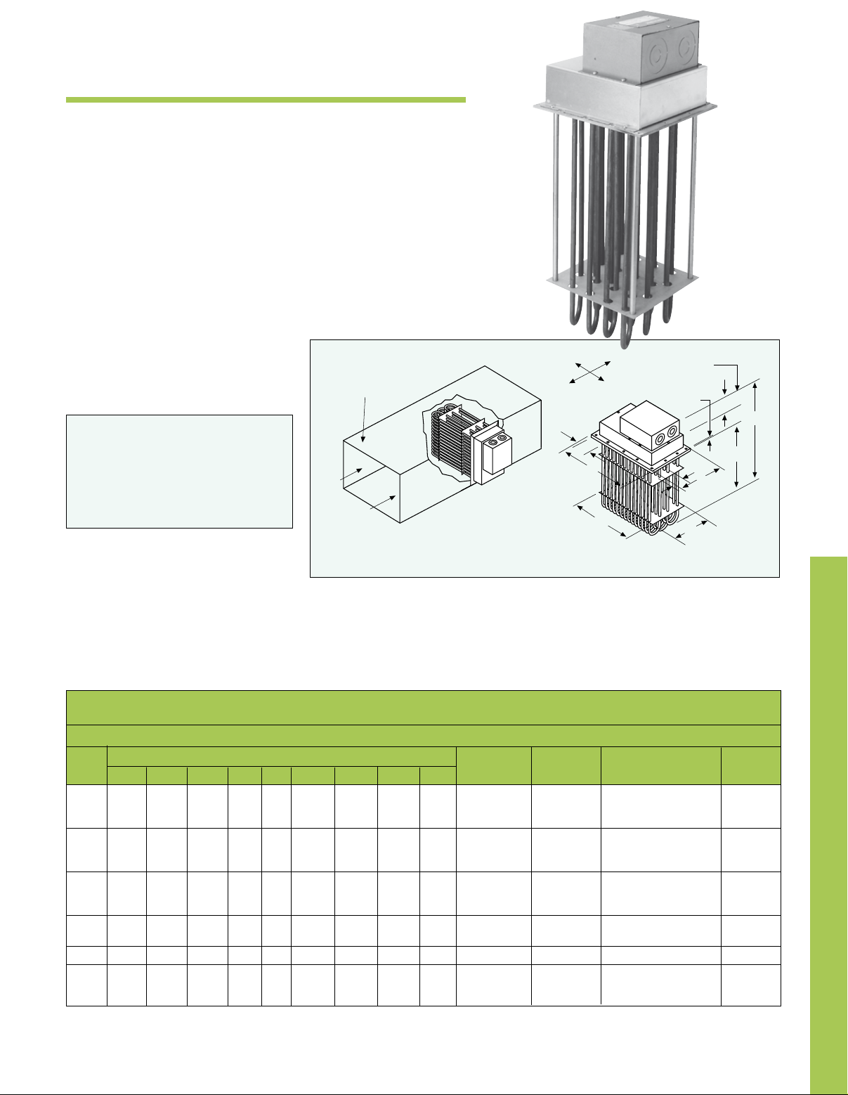
Duct opening is
D + 1⁄4" x M + 1⁄4"
Air
Air
ADH-005/480V/3P shown
smaller than actual size.
II
III
I
H
A
Airflow
Direction
IV
D
1
⁄2"
3-
E
4"
C
B
K
L
M
FEATURES
Rugged construction. Sturdy 0.475"
diameter tubular elements mounted
to a heavy
Terminal housing made of 18 gage
aluminized steel. Element support
plates of 16 gage aluminized steel are
held in place by stainless steel support
rods. High temperature units have the
1
⁄4 or 3⁄8" thick steel flange.
Hairpin elements
additional feature of stainless steel
material for the 3" insulation housing
and element support plate—all of which
provides superior rigidity, strength and
reliability.
Long life metal sheath tubular
elements—Corrosion/oxidation
resistant sheath. High grade
Incoloy sheath material for excellent
corrosion/oxidation resistance at high
operating temperatures.
DimensionsTypical Installation
To Order
ADH-Low-Medium Temperature (30 W/in2)
Dimensions - Inches
No. No.
Wt.
kW A B C D E H K L M Elem. Circ. Model No. lbs
5 55⁄8 201⁄8 281⁄8 4 1⁄4 21⁄2 31⁄2 111⁄8 91⁄2 3 1 ADH-005/480V/3P 8
10 75⁄8 203⁄8 281⁄8 6 1⁄4 31⁄2 31⁄2 111⁄8 91⁄2 6 1 ADH-010/480V/3P 15
15 95⁄8 203⁄8 281⁄8 8 1⁄4 3 31⁄2 111⁄8 91⁄2 9 1 ADH-015/480V/3P 25
20 115⁄8 203⁄8 281⁄8 10 1⁄4 23⁄4 31⁄2 111⁄8 91⁄2 12 1 ADH-020/480V/3P 35
25 135⁄8 203⁄8 281⁄8 12 1⁄4 31⁄4 31⁄2 111⁄8 91⁄2 15 1 ADH-025/480V/3P 40
30 155⁄8 203⁄8 281⁄4 14 3⁄8 33⁄4 31⁄2 111⁄8 91⁄2 18 1 ADH-030/480V/3P 55
35 175⁄8 203⁄8 281⁄4 16 3⁄8 41⁄4 31⁄2 111⁄8 91⁄2 21 1 ADH-035/480V/3P 65
40 195⁄8 203⁄8 281⁄4 18 3⁄8 43⁄4 31⁄2 111⁄8 91⁄2 24 2 ADH-040/480V/3P 70
45 215⁄8 203⁄8 281⁄4 20 3⁄8 51⁄4 31⁄2 111⁄8 91⁄2 27 2 ADH-045/480V/3P 80
50 235⁄8 203⁄8 281⁄4 20 3⁄8 53⁄4 31⁄2 111⁄8 91⁄2 30 2 ADH-050/480V/3P 90
60 275⁄8 203⁄8 281⁄4 26 3⁄8 41⁄2 31⁄2 111⁄8 91⁄2 36 2 ADH-060/480V/3P 105
100 435⁄8 203⁄8 281⁄4 42 3⁄8 53⁄8 31⁄2 111⁄8 91⁄2 60 5 ADH-100/480V/3P 175
162 395⁄8 35 427⁄8 38 3⁄8 47⁄8 31⁄2 111⁄8 91⁄2 54 6 ADH-162/480V/3P 185
216 275⁄8 35 427⁄8 26 3⁄8 41⁄2 37⁄8 20 183⁄8 72 6 ADH-216F/480V/3P 240
270 335⁄8 35 427⁄8 32 3⁄8 51⁄2 37⁄8 20 183⁄8 90 8 ADH-270F/480V/3P 300
Ordering Example: ADH-035/480V/3P, 21-element, 3-phase, 480V high temperature air duct heater.
Refer to J-3 for application data.
J-1
J
Page 2
Low watt density resistor wire. Watt
density on the heating coil is designed
for low watt density operation by
increasing the coil diameter, gage
and length of resistance wire to give
maximum surface area and low
operating coil surface temperature—
providing longer coil life.
Easy element replacement. Individual
elements are mechanically fastened to
the flange permitting convenient, easy
replacement.
Low wiring compartment
temperatures. Made possible by the
addition of a one-inch thick blanket of
insulation in the terminal box—allows
use of low temperature field wiring
instead of expensive high temperature
busbars and wire. High temperature
units include additional three inches
of insulation to help reduce duct heat
losses.
Easy access to simplified field
wiring terminals. Terminal housing
is completely removable for maximum
access to field wiring terminals.
Individual terminal blocks with threaded
stud type terminals are provided for
each circuit to permit quick positive
attachment of circuit wiring conductors.
Dirt/dust resistant terminal housing.
Terminal housing made of solid heavy
gauge aluminized steel rather than
perforated metal to resist dirt and
dust accumulation on the electrical
connections and thus provide longer
service life.
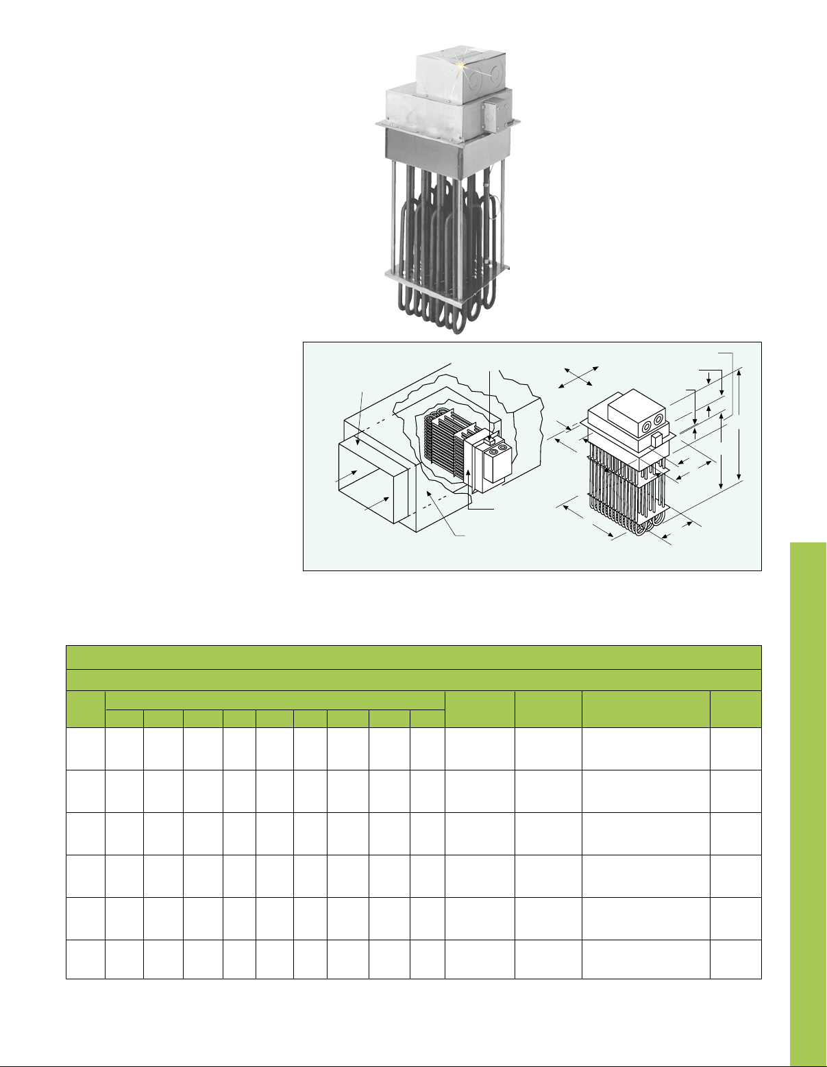
Thermocouple
Sheet Metal
Duct
Air
Air
Terminal Box
Insulation
(3" max.)
Flange mounting gasket. Packed
separately with each duct heater to
ADHT-005/480V/3P shown
smaller than actual size.
III
I
H
A
Insulated
Standoff
Collar
minimize leakage between the
flange and air duct.
II
IV
D
Airflow
Direction
DimensionsTypical Installation
3-1/2"
E
M
3-5/8"
4"
K
L
C
B
J
To Order
ADHT-High Temperature (20 W/in2)
kW A B C D E H K L M Elem. Circ. Model No. lbs
5 55⁄8 201⁄8 281⁄8 4
Dimensions - Inches
1
⁄4 21⁄2 31⁄2 111⁄8 91⁄2 3 1 ADHT-005/480V/3P 10
No. No. Wt.
10 75⁄8 203⁄8 281⁄8 6 1⁄4 31⁄2 31⁄2 111⁄8 91⁄2 6 1 ADHT-010/480V/3P 20
15 95⁄8 203⁄8 281⁄8 8 1⁄4 3 31⁄2 111⁄8 91⁄2 9 1 ADHT-015/480V/3P 30
20 11
5
⁄8 203⁄8 281⁄8 10 1⁄4 23⁄4 31⁄2 111⁄8 91⁄2 12 1 ADHT-020/480V/3P 40
25 135⁄8 203⁄8 281⁄8 12 1⁄4 31⁄4 31⁄2 111⁄8 91⁄2 15 1 ADHT-025/480V/3P 50
30 155⁄8 203⁄8 281⁄4 14 3⁄8 33⁄4 31⁄2 111⁄8 91⁄2 18 1 ADHT-030/480V/3P 65
35 17
5
⁄8 203⁄8 281⁄4 16 3⁄8 41⁄4 31⁄2 111⁄8 91⁄2 21 1 ADHT-035/480V/3P 80
40 195⁄8 203⁄8 281⁄4 18 3⁄8 43⁄4 31⁄2 111⁄8 91⁄2 24 2 ADHT-040/480V/3P 90
45 215⁄8 203⁄8 281⁄4 20 3⁄8 51⁄4 31⁄2 111⁄8 91⁄2 27 2 ADHT-045/480V/3P 100
50 23
5
⁄8 203⁄8 281⁄4 22 3⁄8 53⁄4 31⁄2 111⁄8 91⁄2 30 2 ADHT-050/480V/3P 110
60 275⁄8 203⁄8 281⁄4 26 3⁄8 41⁄2 31⁄2 111⁄8 91⁄2 36 2 ADHT-060/480V/3P 130
80 355⁄8 203⁄8 281⁄4 34 3⁄8 43⁄8 31⁄2 111⁄8 91⁄2 48 4 ADHT-080/480V/3P 175
90 39
5
⁄8 203⁄8 281⁄4 38 3⁄8 47⁄8 31⁄2 111⁄8 91⁄2 54 5 ADHT-090/480V/3P 200
100 435⁄8 203⁄8 281⁄4 42 3⁄8 53⁄8 31⁄2 111⁄8 91⁄2 60 5 ADHT-100/480V/3P 220
120 275⁄8 35 427⁄8 26 3⁄8 41⁄2 31⁄2 111⁄8 91⁄2 36 4 ADHT-120/480V/3P 205
160 35
5
⁄8 35 427⁄8 34 3⁄8 43⁄8 31⁄2 111⁄8 91⁄2 48 8 ADHT-160/480V/3P 270
180 395⁄8 35 427⁄8 38 3⁄8 47⁄8 31⁄2 111⁄8 91⁄2 54 6 ADHT-180/480V/3P 305
240 275⁄8 35 427⁄8 26 3⁄8 41⁄2 37⁄8 20 183⁄8 72 8 ADHT-240F/480V/3P 400
Ordering Example: ADHT-020/480V/3P is a 12-element, 3-phase, 480V high temperature air duct heater.
Refer to J-3 for application data. All ADHT models come with K type overtemp thermocouple.
J-2
Page 3
HIGH TEMPERATURE
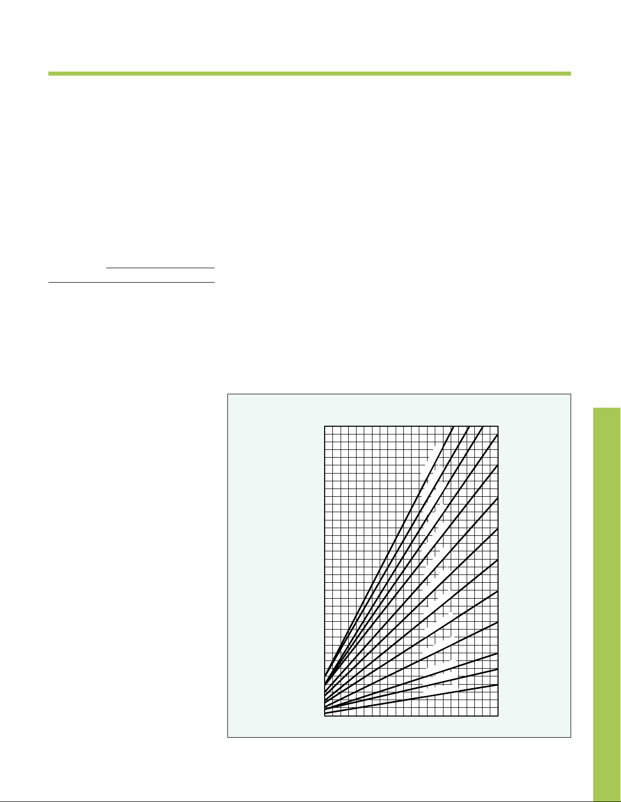
HUNDRED CUBIC FEET OF AIR PER MINUTE
AIR DUCT HEATERS
APPLICATION GUIDE
Selecting heater size. Refer to
Technical Section for examples on
determining kW requirements. For
quick estimating purposes, the following
formula may be used for standard
conditions (includes 1.2 safety factor):
kW = CFM x temp. diff/2500
Maximum work temperature. Types
ADH and ADHT process air heaters
can generally be used at the following
maximum temperature shown, provided
the minimum air velocity is maintained
uniformly through the heater:
Air Velocity
Max. Outlet Air Temp. °F
(ft/sec) ADH ADHT
4 800 1050
9 800 1100
16 800 1150
25 800 1200
36 800 1200
Application assistance. OMEGALUX
sales/application engineers are
available to assist you in the design
or selection of equipment.
INSTALLATION
MOUNTING TIPS
Low temperature duct heaters can be
fastened directly to the sheet metal duct
work with bolts or sheet metal screws.
High temperature duct heaters are
generally mounted to a field fabricated
stand off collar from the ductwork to
position the heater such that the 3"
insulation housing is in the same plane
as the duct insulation.
All heaters can be mounted in any
position; top, side or bottom (preferred)
entry. Minimum duct size is A or L
dimension plus
5
plus 1
⁄8".
Provide adequate heater support.
Consideration should be given to
installing hangers or some other means
of heater support whenever there is
any question about the ability of the
ductwork to support the heater weight.
Overtemperature protection.
All heaters should include an
overtemperature (overheat) control
whose temperature sensing element
is located on the air discharge side of
the heater as close to the heater as is
practical. High temperature ADHT units
include an overtemperature (Type K)
thermocouple as standard.
3
⁄8" and B dimension
Additional protection can be achieved
by installing an air flow or pressure
differential switch to protect the heater
against low air flow conditions.
Operation controls. Selection of
these controls, thermostat, SCR
units, contactors etc., depends on the
degree of accuracy required, reliability,
electrical rating of heater and economic
considerations.
Field power & control circuit wiring.
Must be capable of carrying the
electrical load and be protected by
overcurrent protective devices, such
as fusing, circuit breakers or ground
fault detection in accordance with the
requirements of the NEC and local
codes as applicable.
Tandem mounting. Multiple heaters
may be mounted in tandem with
each other provided the maximum
recommended outlet air temperature
is not exceeded.
Heat Requirements for Air
Based on .08 lbs./cu. ft. Weight
and a specific Heat of .237 Btu./lb./ϒF
170
150
130
110
90
KILOWATTS
70
50
30
10
0
1 357911
OPTIONS AVAILABLE
Gas tight design. Achieved by the
use of threaded compression fittings
with fiber washers to attach heating
elements to flange—prevents leakage
of ducted air into terminal housing.
Overtemperature protection.
Thermocouple welded to the element
sheath surface and wired to a terminal
block can be provided for accurate
overheat protection. Standard on high
temperature units.
Moisture or explosion-resistant
terminal housings are available for
those applications requiring special
terminal protection.
J
600ϒF RISE
550ϒF RISE
500ϒF RISE
450ϒF RISE
400ϒF RISE
350ϒF RISE
300ϒF RISE
250ϒF RISE
200ϒF RISE
150ϒF RISE
100ϒF RISE
75ϒF RISE
50ϒF RISE
J-3
 Loading...