

Page 1
4-20mA OUTPUT CURRENT
SENSOR SERIES
Installation & Operation Instructions
Phone: 1-888-967-5224
Website: workaci.com
PRECAUTIONS
• This product is not intended to be used for
Life or Safety applications.
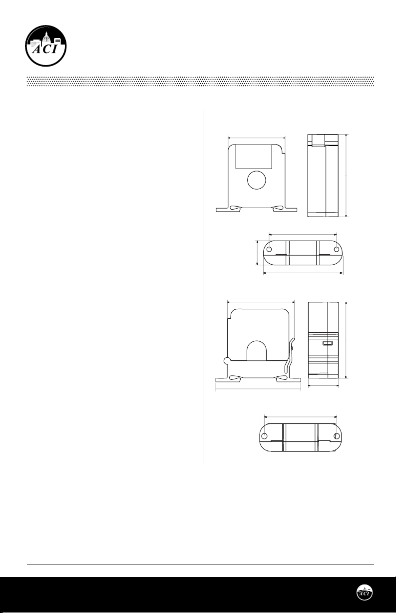
FIGURE 1: DIMENSIONS
Solid-Core
2.36” (59.94mm)
• This product is not intended for use in any
hazardous or classied locations.
• The A/CTA2 and A/SCTA2 Series Current
Sensors must be used on Insulated
2.77”
(70.45mm)
Conductors Only.
HIGH VOLTAGE
• Disconnect and lock out all power sources
before installation as severe injury or death
may result from electrical shock due to
contact with high voltage wires.
1.03”
(26.16mm)
GENERAL INFORMATION
The 4-20 mA Output Analog Current Sensors are designed
for use in any AC current monitoring application in which
you are looking to monitor a particular piece of
equipment. Applications may include monitoring a
resistive type load such as an incandescent light bulb,
heating element as well as any single speed linear load.
For currents monitored above 250 Amps, the CTA2-5 and
SCTA2-5 are ideal for use with a step down Ratio:5A
Output CT (Current Transformer) in stepping down
current in a monitored conductor to a proportional 0 to 5A
output signal. The current sensors are available in both
solid and split-core versions which also includes a
Patented (Pat. No. US 7,416,421) 35 mm Din Rail mounting
foot for easy installation in panel mount applications. The
solid-core versions are a great choice for new installations
or OEM applications in which cost sensitivity, lower trip
points and environmental issues like dust and moisture
may be of concern. The split-core version of the current sensors work great in retrot applications and for use on service
technicians vehicles since one or two parts will work in most applications and can be easily installed without
disconnecting any wires.
Split-Core
2.55” (64.69mm)
3.24” (82.23mm)
2.87” (72.80mm)
3.35” (84.99mm)
2.87” (72.77mm)
2.77”
(70.35mm)
1.10” (28.02mm)
INSTALLATION
Make sure that all installations are in compliance with all national and local electrical codes. Only qualied
individuals that are familiar with codes, standards, and proper safety procedures for high-voltage
installations should attempt installation. The current sensor is a 2-wire, 4 to 20 mA Loop Powered device
Page 1
Automation Components, Inc.
2305 Pleasant View Road | Middleton, WI 53562
Phone: 1-888-967-5224 | Website: workaci.com
Version: 9.0
I0000789
Page 2
that requires a regulated +13.5 to 30VDC external
power source.
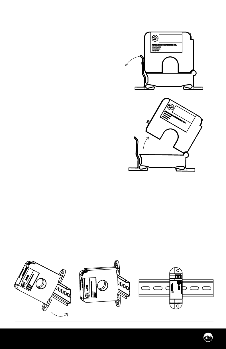
FIGURE 2: OPENING A/SCS2 SERIES
The current sensor may be mounted in any position
A/SCTA2-5
using the two #8 x ¾” Tek screws and the mounting
holes in the base, or snapped directly on to the 35mm
DIN rail (See Figure 3). Leave a minimum distance of
1” (3 cm) between the current sensor and any other
magnetic devices such as contactors and
transformers.
Latch Operation for A/SCTA2 S eries
Press down on the side tab and swing the top of the
unit up to open the split core current sensor as shown
in Figure 2. Press down rmly on the cover to close
the current sensor. An audible “click” will be heard as
the tab slides over the tongue on the base.
A/SCTA2-5
CAUTION: Mating surfaces of the magnetic core are
exposed when the sensor is open. Electrical contact
grease, present on the cores to prevent corrosion, can
capture grit and dirt if care is not exercised. Operation can be impaired if anything prevents good
contact between pole pieces. Visually check the
mating parts of the core before closing the current
sensor.
Current Sensor Setup
The amperage range selected represents the maximum current that can be applied to the conductor being
monitored, Do not exceed! All current sensors with selectable ranges will have the range selection jumper
factory set on the high range. For models with eld selectable amperage ranges, select the correct amperage range using the range selection jumper. Note that all -RMS models have True RMS outputs and should
be used with Variable Frequency Drives.
Note: An extra jumper shunt is included. It can be discarded if not needed.
Note: In applications where high vibrations are encountered, ACI recommends to use the jumper shunt
without tab. A pliers can help with jumper shunt installation onto the pins.
FIGURE 3: DIN RAIL INSTALLATION
Page 2
Automation Components, Inc.
2305 Pleasant View Road | Middleton, WI 53562
Phone: 1-888-967-5224 | Website: workaci.com
Version: 9.0
I0000789
Page 3
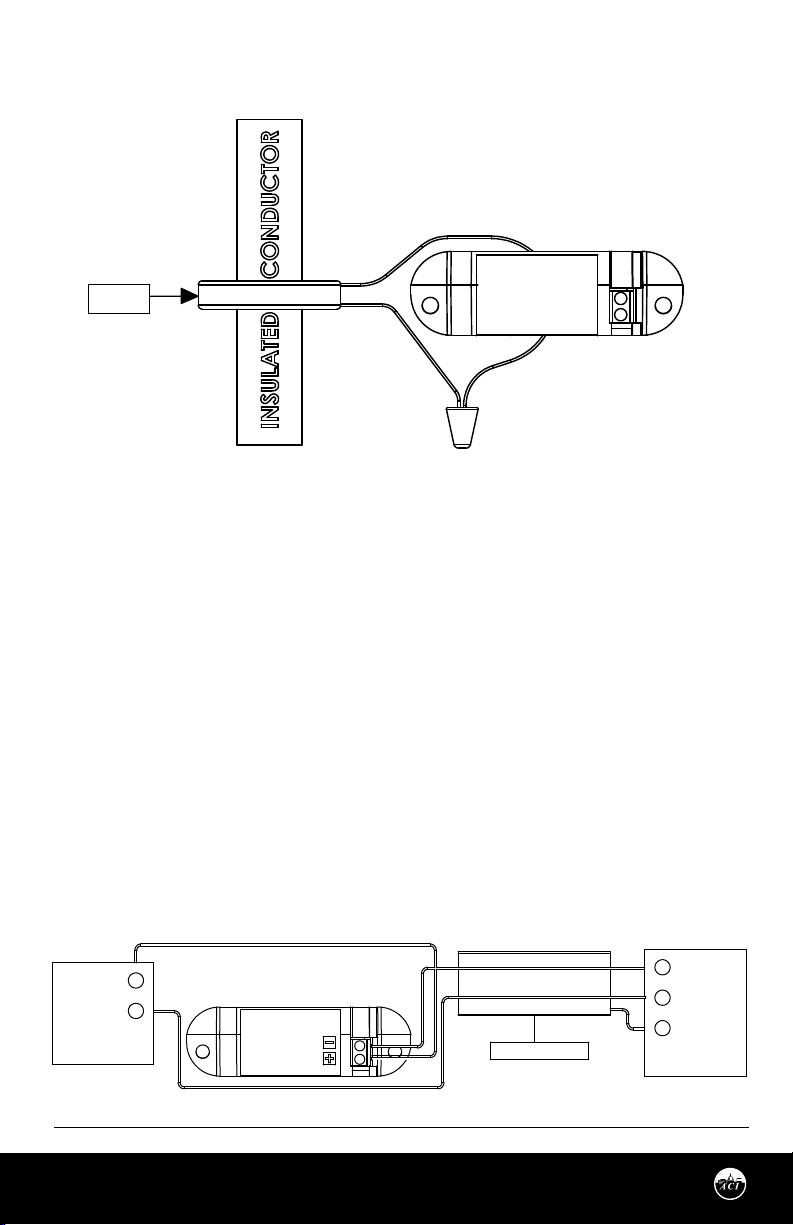
FIGURE 4: CURRENT TRANSFORMER
600: 5A
C.T
A/SCTA2-5
APPLICATION NOTES
For load currents greater than sensor maximum continuous current rating:
For applications in which the normal operating current is greater than 250 Amps or for conductors larger
than 0.750” (1.90 cm) in diameter, an external 5 Amp Current Transformer must be used as shown in Figure
4. Use the A/CTA2-5 or A/SCTA2-5 to scale the 5A current to a 4-20ma current.
WIRING INSTRUCTIONS
ACI recommends the use of a two conductor 16 to 22 AWG shielded cable, copper wire only, for all 4 to 20mA
current sensor installations. A maximum wire length of less than 30 meters (98.4 feet) should be used
between the current sensors and the Building Management System or controller. All wiring must comply
with all local and National Electric Codes.
Note: When using a shielded cable, be sure to connect only (1) end of the shield to ground at the controller.
Connecting both ends of the shield to ground may cause a ground loop.
When removing the shield from the sensor end, make sure to properly trim the shield to prevent any chance
of shorting. The current sensor terminals are polarity sensitive and represent a linear and proportional 4 to
20mA output signal. Tighten the screws at the terminal block connections to the recommended torque of 0.5
to 0.6 Nm (4.43 to 5.31 in-lbs.). The aperture (hole) size of the current sensor is 0.75” (1.90 cm).
FIGURE 6: ANALOG CIRCUIT
DC POWER
SUPPLY
+
-
4-20mA
13.5-30VDC
13.5 to 30 VDC
Automation Components, Inc.
2305 Pleasant View Road | Middleton, WI 53562
Phone: 1-888-967-5224 | Website: workaci.com
Page 3
SHIELDED CABLE
4 to 20 mA
SIGNAL INPUT
AI
COMMON
GND
(SHIELDED)
Building Automation
System
Version: 9.0
I0000789
Page 4
TROUBLESHOOTING
PROBLEM
No reading
Erratic readings
Inaccurate readings
Current Sensor is operating at a
low-level current or failing to operate
within the accuracy specications.
SOLUTION(S)
- Conrm that you have +13.5 to 30VDC in series with the current sensor output terminals
and the analog input of the control panel.
- Check the polarity of the circuit.
- Verify that the terminals are screwed down, wires are rmly in place.
- Disconnect the input to the control panel and then insert a current meter (mA range) in
series with the current sensor output to verify that the circuit is working properly.
- Verify that the wires are terminated properly.
- Check that the +13.5 to 30VDC input is clean. In areas of high RF interference, shielded
cable may be necessary to stabilize signal.
- If you suspect that the current sensor is not reading within the accuracy specications,
please contact the factory for assistance.
-Visually check the mating parts of the core to ensure there is no debris between the split
contacts. See Figure 2.
-Remove all debris or dust manually and close the current sensor.
-Continue to retest the sensor in your application.
STANDARD ORDERING
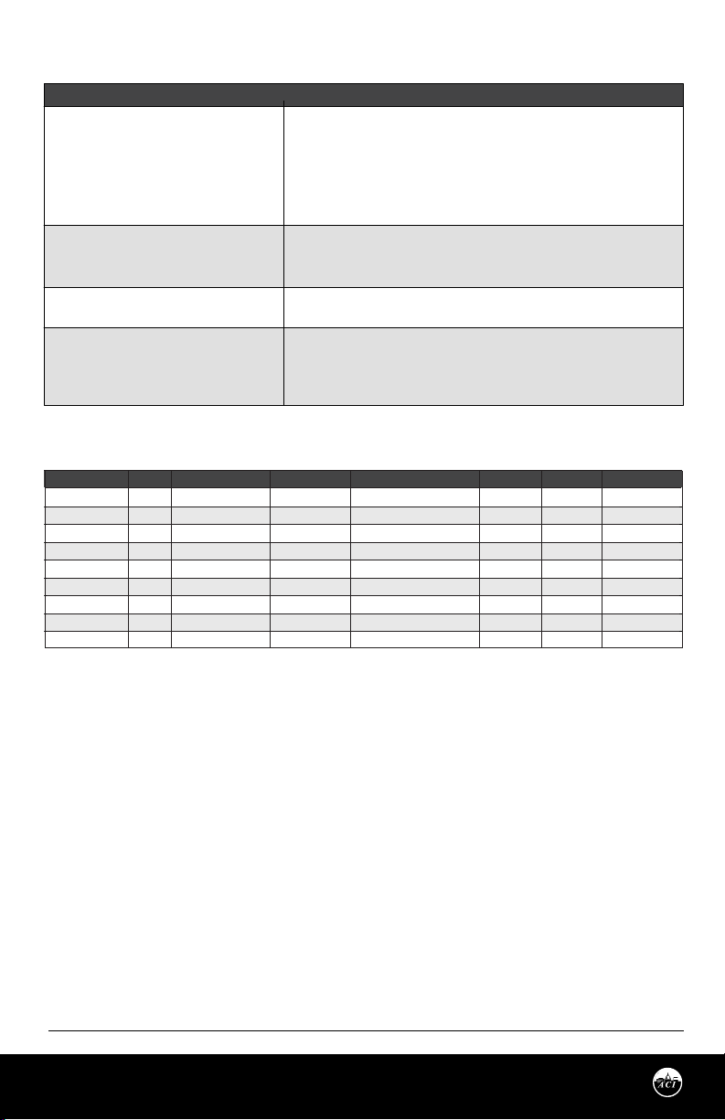
Model #
A/CTA2-5
A/CTA2-50
A/CTA2-250
A/SCTA2-5
A/SCTA2-50
A/SCTA2-200
A/CTA2-50-RMS
A/CTA2-250-RMS
A/SCTA2-50-RMS
Note*: Only the 100 Amp Range will meet the accuracies over the operating frequency range of 15 to 100 Hz (See Specication Table)
Item #
142379
142378
142377
142376
142375
142374
142373
142372
142371
Selectable Ranges
0 to 5A
0 to 10/20/50A
0 to 100/200/250A
0 to 5A
0 to 10/20/50A
0 to 100/150/200A
0 to 10/20/50A
0 to 100*/200/250A
0 to 10/20/50A
Measurement
Average
Average
Average
Average
Average
Average
True RMS
True RMS
True RMS
AC Waveform
Pure Sinusoidal
Pure Sinusoidal
Pure Sinusoidal
Pure Sinusoidal
Pure Sinusoidal
Pure Sinusoidal
Distorted & Pure Sinusoidal
Distorted & Pure Sinusoidal
Distorted & Pure Sinusoidal
Solid-Core
•
•
•
•
•
Split-Core
•
•
•
•
Output Signal
4 to 20 mA
4 to 20 mA
4 to 20 mA
4 to 20 mA
4 to 20 mA
4 to 20 mA
4 to 20 mA
4 to 20 mA
4 to 20 mA
Automation Components, Inc.
2305 Pleasant View Road | Middleton, WI 53562
Phone: 1-888-967-5224 | Website: workaci.com
Page 4
Version: 9.0
I0000789
Page 5
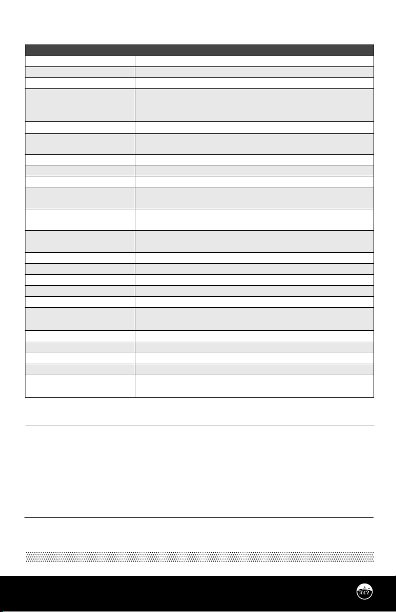
PRODUCT SPECIFICATIONS
SENSOR NON-SPECIFIC INFORMATION
Monitored Current Type:
Maximum AC Voltage:
Isolation Voltage:
Operating Frequency Range :
Core Style:
Supply Voltage:
Maximum Load Resistance @ 24 VDC:
Supply Current:
Sensor Amperage Range:
Output Signal | Maximum Output
Signal:
Accuracy :
Response Time:
Aperture Size:
Din Rail Size:
Operating Temperature Range:
Operating Humidity Range:
Storage Temperature | RH Range:
Enclosure Material | Flammability
Rating:
Wiring Connections:
Wire Recommendations:
Wire Size:
Terminal Block Torque Rating:
Minimum Mounting Distance:
Note:
All current output sensors are calibrated at an ambient room temperature of 71ºF (21.5ºC) |
Note: Only the 0 to 100 Amp range in the A/CTA2-250-RMS will meet accuracy specications from 15 to 100 Hz
AC Current
600 VAC
2200 VAC
A/CTA2 & A/SCTA2 Series: 40 to 1KHz | A/CTA2-50-RMS & A/SCTA2-50 RMS: 15 to 100
Hz | A/CTA2-250-RMS (0-100A Range): 15 to 100 Hz | A/CTA2-250-RMS (0-200/250A Ranges): 30
to 100 Hz
Solid-Core and Split-Core Versions available (See Ordering Grid pg. 5 )
+8.5 to 30 VDC (Reverse Polarity Protected)
250 Ohm Load (1-5 VDC): +13.5 to 30 VDC | 500 Ohm Load (2-10 VDC): +18.5 to 30 VDC
775 Ohms (Formula: (24 VDC – 8.5 VDC) / 0.020A )
25 mA minimum
See Ordering Grid pg. 5 (Field Selectable)
4 to 20 mA (2-Wire, Loop Powered) | Limited to 25 mA
All Models: +/- 1% of Selected Range except A/SCTA2-50-RMS: +/- 2% from 15 to 20 Hz
+/- 1% from 20 to 100 Hz
A/CTA2-xxx and A/SCTA2-XXX: < 600 mS (Rise and Fall Time)
A/CTA2-xxx-RMS & A/SCTA2-50-RMS: 600 mS (Rise Time) and 2800 mS (Fall Time)
0.75” (19.05 mm)
35 mm (U.S. Patent No. 7,416,421)
5 to 104ºF (-15 to 40ºC)
0 to 95%, non-condensing
41 to 95°F (5 to 35°C) | 40% to 85% RH, non-condensing
PC/ABS (Polycarbonate/ABS Blend) | UL94-V0
2 Position, Screw Terminal Block (Polarity Sensitive)
2 Conductor (Shielded Cable)
18 to 24 AWG (0.823 mm to 0.205 mm) Copper Wires only
4.43 to 5.31 in-lbs. (0.5 to 0.6 Nm)
1” (2.6 cm) between current sensor & other magnetic devices (Relays, Contactors,
Transformers)
WARRANTY
The ACI Current Switch Series are covered by ACI’s Five (5) Year Limited Warranty, which is located in the front of
ACI’S SENSORS & TRANSMITTERS CATALOG or can be found on ACI’s website: www.workaci.com.
W.E.E.E. DIRECTIVE
At the end of their useful life the packaging and product should be disposed of via a suitable recycling
centre. Do not dispose of with household waste. Do not burn.
Page 5
Automation Components, Inc.
2305 Pleasant View Road | Middleton, WI 53562
Phone: 1-888-967-5224 | Website: workaci.com
Version: 9.0
I0000789
Page 6
NOTES
Page 6
Automation Components, Inc.
2305 Pleasant View Road | Middleton, WI 53562
Phone: 1-888-967-5224 | Website: workaci.com
Version: 9.0
I0000789
Page 7
NOTES
Page 7
Automation Components, Inc.
2305 Pleasant View Road | Middleton, WI 53562
Phone: 1-888-967-5224 | Website: workaci.com
Version: 9.0
I0000789
Page 8
Automation Components, Inc.
2305 Pleasant View Road
Middleton, WI 53562
Phone: 1-888-967-5224
Website: workaci.com
Page 8
Automation Components, Inc.
2305 Pleasant View Road | Middleton, WI 53562
Phone: 1-888-967-5224 | Website: workaci.com
Version: 9.0
I0000789
 Loading...