

Page 1

User’s Guide
Shop online at
omega.com
e-mail: [email protected]
For latest product manuals:
www.omegamanual.info
SM
ACC101, ACC102A, ACC103,
ACC301A, ACC310, ACC320
Accelerometers
Page 2

omega.com [email protected]
Servicing North America:
U.S.A. Omega Engineering, Inc.
Headquarters: Toll-Free: 1-800-826-6342 (USA & Canada only)
Customer Service: 1-800-622-2378
Engineering Service: 1-800-872-9436
Tel: (203) 359-1660
e-mail: [email protected]
For Other Locations Visit omega.com/worldwide
(USA & Canada only)
(USA & Canada only)
Fax: (203) 359-7700
The information contained in this document is believed to be correct, but OMEGA accepts no liability for any errors it contains,
and reserves the right to alter specifications without notice.
Page 3

ACC
101,102A,103,301A,310,320
ACCELEROMETERS OPERATOR'S MANUAL
TABLE OF CONTENTS
SECTION 1 - INTRODUCTION
SECTION 2 -
·UNPACKING
3 -
SECTION
What is an Accelerometer?.................................................................................. 2
How Does it Work?
High Impedance or Low Impedance? ....
Low Impedance Micro Circuit
Noise in Accelerometers
General Characteristics ...............
UNDERSTANDING YOUR ACCELEROMETER ............
..
........................................................................................
..
..........................................
SECTION 4 - POWER REQUIREMENTS ..............................................
Power Supplies .................................................................................................. 5
SECTION 5 - CONNECTOR WIRING ...................................................
Coaxial Connectors............................................... ....... ............. ........................ 7
Two Pin Connectors..........
Four Pin Connectors
....
........................................................................................... 7
SECTION 6 - CABLING TECHNIQUES.................................................
Splicing and Extending Cables............................................................................ .8
Securing Cables
.................................................................................................. 8
SECTION 7 - MOUNTING THE ACCELEROMETER ............................ 10
Stud Mounting..
Adhesive Mounting
Adhesive Mounting Bushings..........................
Magnetic Mounting…………..........
................................................................................................... 10
.....
....................................
SECTION 8 - SPECIFICATIONS.......................................................... 1
Basic Sensitivity ................................................................................................. 14
Basic Frequency Response ........
ACC 101 Specifications .......
ACC 102A Specifications ..................
.
ACC 103 Specifications
ACC 301A Specifications .....
ACC 310 Specifications
ACC 320 Specifications .....
Notes……………………………………………………………………………………. 21
WARRANTY………………………………………………………………………….… 22
........................
.
........................
...................................................................... ..1
YOUR ACCELEROMETER ...................... 1
..........................................................
.
..
....................
.
.....................................
............................................................................. 7
..................................................
...........
.
.......
....
.
............
.
............
.
.
..........
......................
......................................... .3
...
...
...................
...
...................
....
......................................................... 14
.....................
..
............................................................... 16
...
.......................................................... 17
....
...
.........................
...
.......................................................... 19
....
...
.........................
...
............................
...............
...............
...
.................. 3
................................. 4
.....
........................ 10
.....
....................... 11
.................... 12
...
........... 15
.................. 18
..................... 20
.....
2
.. 2
2
5
7
8
4
Page 4

jj
Page 5

1
SECTION 1 • INTRODUCTION
Thank you tor selecting our accelerometer for your application. You
made
an
and
outstanding choice
we
are glad
to
provide you with the
by
selecting this OMEGA Engineering
best
accelerometer that
technology can offer. This equipment has set the world standard
excellence and should provide you with years
of
faithful
service.
Before you use your accelerometer, please read this manual to ensure
maximum performance
equipment, please
this
1
(800) 622-2378. There
you
between 8:30 AM
of
your
unit. If
you should have any problem
call our Customer Service Department
are customer service people available to help
and 5:00 PM (EST) Monday through
•
SECTION 2
Remove the
there a re any questions
Service Department
Upon
signs
transit.
The carrier
UNPACKING YOUR ACCELEROMETER
packing list
and verify that
all equipment has been received. If
about the shipment, please call OMEGA
at 1-(800) 622-2378 or (203)
receipt
of
of
the shipment, inspect the container
damage. Take particular note of any evidence of
Immediately report any damage
NOTE:
will
not
honor any claims unless
to
359·1660.
the shipping
all shipping material is saved
and equipment for
agent.
their examination. After examining and removing contents, save the
material and carton
The accelerometer comes packaged in
also contain a cable (
with
an i
nsulating thermal boot. The boot may already
in
the event reshipment Is
Integral or
separate). Each
necessary.
its
own protective case which may
accelerometer
accelerometer and may or may not be removable depending
model. The
package may also contain an isolating mounting stud,
washers, a magnet assembly, or other special part. Care should be
to lose
not
accommodate the accelerometer, accessories, and calibration data
any part including the case which can continue to be
Notice that the serial number and sensitivity of the unit is indicated on
calibration data sheet. The data sheet also includes
specifications that are endorsed for the particular
unit.
have
product
modern
the
with
at
Friday.
Customer
any
rough handling i
packing
is equipped
be
fitted over
upon
the
spacing
taken
used
sheet.
the
performance
for
n
for
the
to
Page 6

SECTION 3 • UNDERSTANDING YOUR ACCELEROMETER
WHAT IS AN ACCELEROMETER?
An accelerometer is a device for measuring shock and vibration.
accelerometer transduces the acceleration of an
analog
acceleration
HOW DOES
Piezoelectric Accelerometers
Mounted within
small mass. This
through
acceleration,
charge output
signal.
The analog signal indicates the real-time,
of
the object on which the accelerometer
IT WORK?
the
the
piezoelectric
the
mass exerts a force
of
accelerometer
mass
is coupled to
crystal.
the crystal that
housing
When the accelerometer
is a
the supporting accelerometer
on
the
is
directly proportional to the
object into a proportional
Instantaneous
IS mounted.
piezoelectric crystal affixed
is
crystal. This
force results
acceleration.
There are many piezoelectric crystal materials that are useful
accelerometer construction. The most
Lead
Metaniobate, Lead Zirconate,
There are
crystals within
The materials
are
For more information
the
also many
selected
the
to
different
accelerometer
and
physical construction used
furnish the p
about
appropriate sales bulletin
mechanical configurations
case.
articular
the construction
or
contact OMEGA Engineering, Inc
common materials used
Lead
Titanat e and natural quartz
of
iIn an
accelerometer
performance characteristics
of
your accelerometer refer
the masses
HIGH IMPEDANCE OR LOW
There
are two
manufactured. These are high i
Essentially,
as
10mV/g
if the
output sensitivity
or
100mV/g, then you
the output sensitivity is specified in units
then
you are
working with
IMPEDANCE?
distinctly different types
mpedance and low
is
specified i n
are
working with
of pC/g
a high
impedance sensor.
of
accelerometers
mV/g
(millivolts
a low
impedance
(pico
coulombs
impedance"
OMEGA's
(see
electronics required
are built right into the
transformation is
signals
desirable
virtually
accelerometers
Figure
3-1
are
transmitted from
for
driving
all
conventional
are the low
impedance type
). A low impedance
to
detect the
case
done
at the
long
cables and it provides a proper Impedance match
data
charge
of the
sensor.
point
the
acquisition
of
sensor.
of
accelerometer
accelerometer is one in
generated
In this
by the
piezoelectric crystal
way, "high" to "low" impedance
measurement and only
The
low
impedance output
systems.
base
subjected
to an
in
input
are ceramic
crystal.
and
design
desired.
.
that are
types.
per g) such
sensor. If
charge per g)
which the
low
impedance
An
to
in
to
a
a
is
to
2
Page 7
3
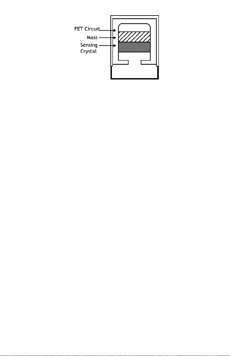
Figure 3-1. Low Impedance Accelerometer
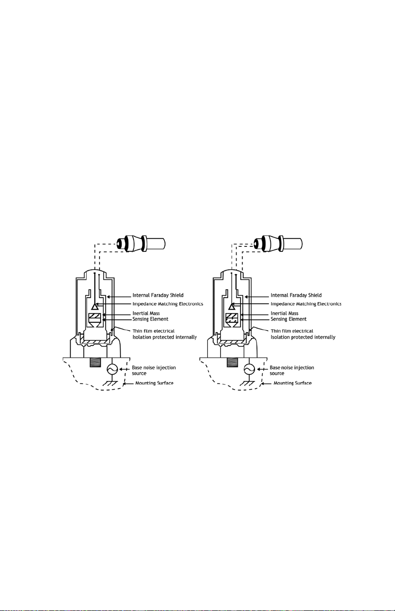
Figure 3-2 Case
LOW IMPEDANCE
OMEGA
impedance
filtering capabilities
properties
are
extremely rugged
without
schemes
•
ESO
•
cross
•
over voltage
When used proper ly within specified
provide
NOISE IN ACCELEROMETERS
Electrical Grounding
An
accelerometer
the output
MICRO
CIRCUIT
has a broad line of micro circuits which yield
output
characteristics.
These hybrid circuits often include
and protection schemes. The specific micro
are
damage
Include:
protection
wire
protection
engineered
or degradation of performance. Additional
protection
to create the output
and
capable
limits, OMEGA accelerometers
years of reliable, trouble-free
service.
signal ground either connected
may be
designed
to the case of the accelerometer or
isolated
accelerometer.
from the case of
Case Grounded Accelerometers
Case grounded accelerometers are
connected electrically
to any conductive surface on which they
are mounted. When these units
care must be
due to
ground noise.
grounded accelerometer
be
allowed
potential
to conduct to
or noise
The case ground type accelerometer should not be
where
ground
loops might be
OMEGA
Model ACC 103 is a case
(see Figure 3-2)
exercised
source.
are
used,
to avoid errors
These
cases should not
any
outside
problem,
grounded
of
with
the
case
characteristics
withstanding extremely
Grounded Accelerometer
such as
accelerometer.
selected
machinery monitoring. The
excellent low
special
desired.
high
circuit
shock
protection
will
for applications
chip
They
Page 8

Case
Isolated Accelerometers
Case isolated accelerometers (see Figure
any conductive surface
from OMEGA are built i
possibility
and
ACC
of
301
ground
are case isolated
on
which
n a variety
noise
interference. OMEGA Models ACC
Figure 3-3. Case Isolated Accelerometer
GENERAL
CHARACTERISTICS
Axis of Sensitivity
Most
accelerometers are
Normally,
normal to
accelerometer
the
accelerometer will transduce shock
the
accelerometer's mounting
will have
orthogonal axes. This
usually amounts
Triaxial Accelerometers
T
riaxial units essentially
into
a
single
package.
signals. In
conductor
accelerometers
triaxial units the three sensors share
requiring
are two wire
to less than 5% of
built to be
some sensitivity
transverse
have
Triaxial units
only a
4-wire
4-wire sy st e ms.
they are mounted.
of
configurations
accelerometers.
sensitive
base. It
or
cross axis sensitivity
the major
three single axis
have
connector. Note
systems and
most
3-3) are
isolated electrically
Isolated
and
to
motion
in
one
and
vibration that i
should
be noted that the
to
motion
in
axis sensitivity.
accelerometers
three
independent
the
that most
triaxial accelerometers
from
accelerometers
eliminate
101, ACC 102,
any
major axis.
s input
the other
is minor and
same
single axis
two
integrated
output
ground
are
4
Page 9
5
SECTION 4
The low
current
analyzers, data collectors,
built in.
The power
or 24 volts.
for
accelerometers will
constant current
powering may impede some of
range,
You
supply
with
POWER SUPPLIES
If the data
• POWER REQUIREMENTS
impedance type
power source.
required
Please refer
clarification
should tak
the output to insure
on its
as high as10 mA
temperature range and noise
e care not to
is
used, it must incorporate
acquisition system being used does
power supply then a
ma nufacture s sing l e
supplies.
Low impedance
preferable
reason, it is
accelerometer. Th
characteristics
battery
these applications where power
Please refer
for
accelerometer should
schematic
power supply.
that a
often appropriate
and can be
pack versions.
to
the appropriate sales bulletins and
each OMEGA power
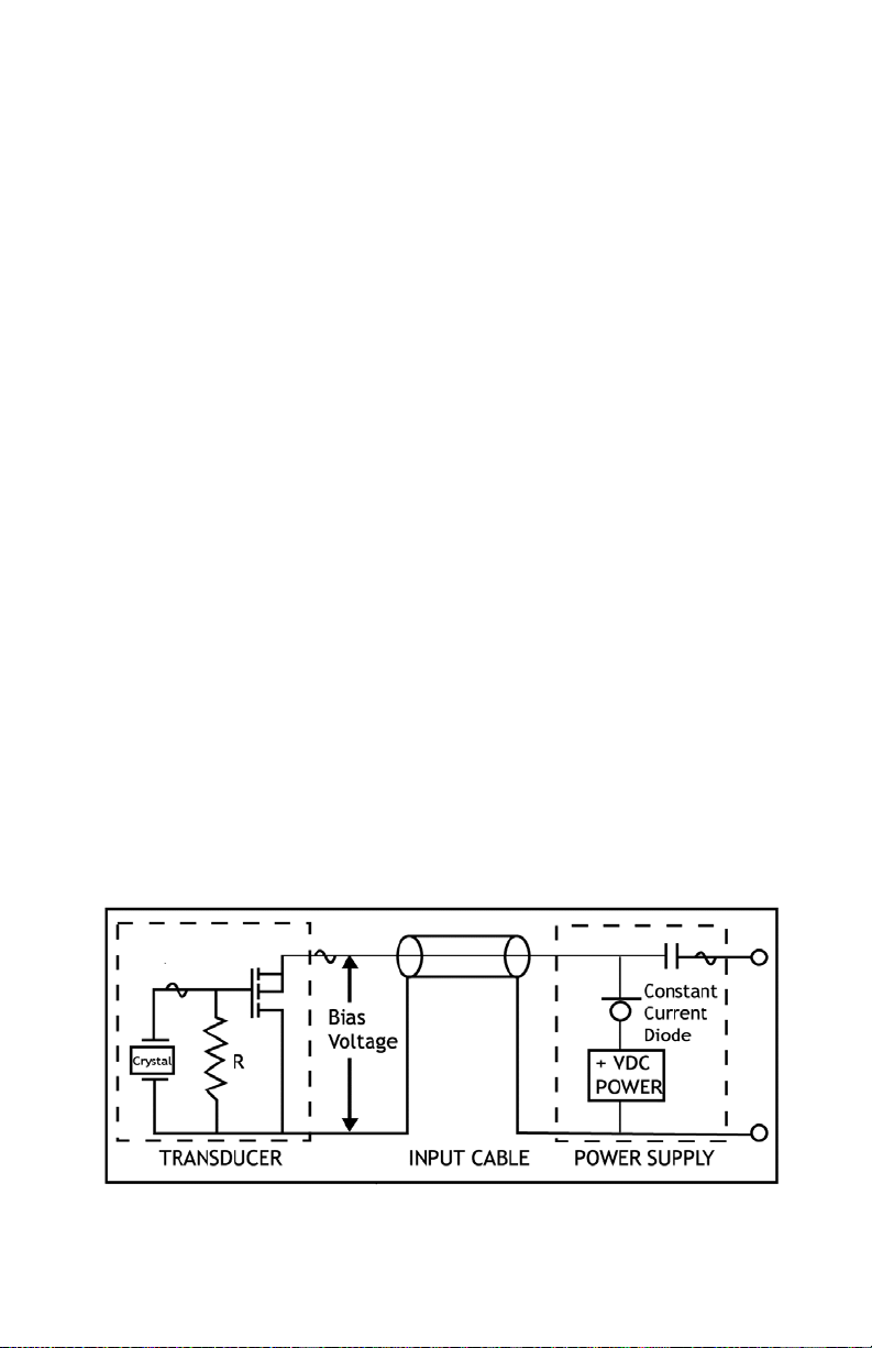
diagram shows the basic components
Figure
4a. - Low
of
accelerometer must
Modern
data
acquisition systems (oscilloscopes,
etc.)
often have this constant current
to drive
not be
the accelerometer
to
the specifications describing your
power requirements. Further note that
damaged
exceed
that the
even If the
or
voltage
the
operating characteristics
level.
the 10
a 2
mA
accelerometer
separate power supply must
be
powered
is
typically 2-4 mA
power
as
high
as 30 volts.
such as
mA current
constant current diode in
limit. If a custom power
Is not over-powered.
not
incorporate its
be used.
channel and multiple channel accelerometer
accelerometers
very
low noise
e battery
offered in either NiCad rechargeable
Regulated
supply.
be
connected
Impedance Accelerometer
do not
regulated power
to use a
-powered unit offers
line power
must stay on for extended periods of time.
Figure
to a
require much
supply be used. For this
battery powered
the
supplies
operating
4-1
illustrates
constant
current power supply. This
within the
Interconnection
power and it is
unit
cleanest (low
are also available for
manuals
how a low
accelerometer and
by a constant
FFT
power
supply
at either
particular model
all
supply provides
15
OMEGA
Incorrect
dynamic
series
own
OMEGA
power
for powering
or
the
noise)
disposable
provided
impedance
Page 10

Some data acquisition systems incorporate the power supply portion of
schematic diagram. In
data acquisition
or “Integrated
Circuit Power" (see Figure
thes
e i
nstances, the accelerometer
system's input connector which may be labeled
4·2).
is
simply
Figure 4·2. Low Impedance Wiring Directly to Instrumentation
For those applications where the data acquisition system does not
constant current power, an external power supply must be used.
accelerometer should
"Acceleration In
connected
Figure 4-3. Low Impedance Wiring to Power Supply and
to the
be connected to
".
The
power supply connector
input of the data acquisition
the power
system
supply
labeled
being used (see Figure
''Output" should
the
fed
into
the
"Accelerometer In"
supply
Essentially, the
connector labeled
Instrumentation
the
be
4-3).
6
Page 11
7
SECTION
Figure
5-1.
Coaxial
COAXIAL CONNECTORS
5-
Most single axis sensors use a
connector
power to the
transmit
shield of
acceleration
TWO PIN
CONNECTORS
Some single axis accelerometers use a two pin connector in place of
the typical coaxial type.
accelerometer
result Is that the
shield of a
to be wired with
Figures 5-1 and
Cable
FOUR PIN CONNECTORS
Triaxial accelerometers use four pin connectors.
the
pins are used for powering _the
three
independent
three
lines.
three integral senso_rs.
triaxial
unit to determine the particular pinout configuration.
CONNECTOR WIRING
coaxial cable terminating
.
In these cases the center conductor is used for sending
accelerometer.
the dynamic acceleration
the coaxial cable
signal. Figure 5·1 shows the coaxial
in
the same way that
two
pins
coaxial accelerometer.
either
coaxial cable
5·2 depict
Connection
The center conductor is also used to
signal from the
accelerometer.
is used as ground for the power supply and
connection.
_ The two pins are
connected
coaxial connectors
correspond
these two
to the center conductor and
The
two pin
or with
conventional
Figure
configuration
shielded
wiring schemes.
5-2.Two-Pin
Cable Connection
(Twisted
Pair)
in a
coaxial
within the
are wired. The
lends itself
twisted pair wire.
In these cases, three of
three
individual
acceleration signals are also present on these same
The fourth pin Is the ground conductor and is shared among all
Please refer t o the individual specifications for your
accelerometers.
The
The
Page 12
SECTION 6 • CABLING TECHNIQUES
As
stated,
no
special "noise treated" cables
low impedance accelerometers. Signals may be
Instrumentation grade two wire twisted pair shielded
SECURING
Figure
conventions minimize cable or connector fatigue failures and
data. Typically, low
or
CABLES
6-1
cable motion.
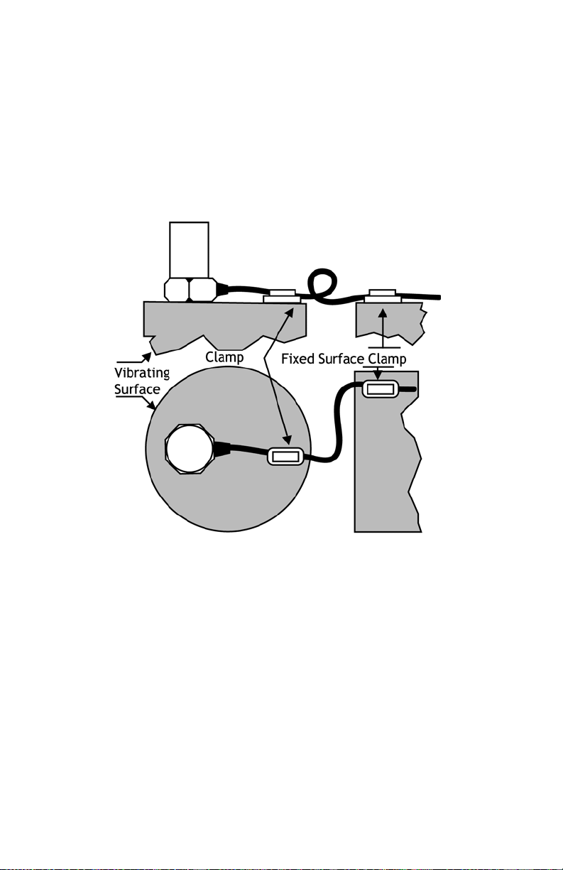
shows
the recommended method of
impedance devices are
are
not
required when operating
run over
or coaxial cable.
securing
affected
any
conventional
cables. These
consequent loss of
by sharp
cable
with
bends
Figure
6-1.Cable
Routing
and
SPLICING & EXTENDING
Common
sense and care
cables. Of course, it is
CABLES
should
always
be used
a good
when splicing and
Idea
to tur n off all power and, if
possible, disconnect the accelerometer and power
this work.
When extending
Male
and
a
coaxial cable, it is
female cable connectors
advisable
are
readily available
(i.e., BNC to BNC, TNC to TNC, 10-32 to 10-32,etc.). These
extension
cables are
available from
OMEGA.
8
Securing
to use coaxial connectors.
supply
when
for this
extending
performing
purpose
adapters
and
Page 13
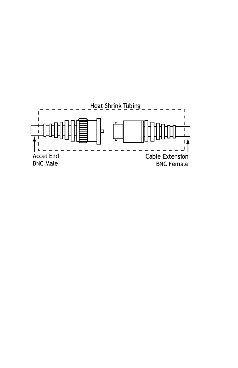
9
The outside
ground. The splice
ground or conduct to any
connector
loop
When working
recommended that
6-2). Some heat
which
shell of
(whic h is signal
noise
Interjection.
provides a
NOTE
these splicing connectors
connector shell should
outside potential or noise
common)
with permanently routed cable
the
splices be
shrink
products
water tight
sealed wi th
contai
seal over the splice.
Is the
not be allowed to touch
touch ground
heat
n heat
activated two-part
accelerometer
source. Letting
can
cause
systems it is
shrink
(see
Figure
epoxy
signal
a
ground
Figure 6-2. Cable Splice with Heat
Shrink
Page 14

SECTION
For
that your
techniques
the
relative merits
7-
MOUNTING THE ACCELEROMETER
reliable vibration data, particularly
accelerometer
provide
accelerometer.
of
seven common mounting
be
for
different frequency
Figure 7-1
is a
at high
mounted correctly.
frequency response
frequencies, it is important
Different mountin
response characteristics fro
plot
describing
techniques.
g
m
the
Figure
7-1.Frequency Response
MOUNTING
Most
from the
removable,
OMEGA accelerometers
bottom
of the unit. This stud may or may not be
depending
STUD
acc el er ometer w i t h the mounting stud,
the mating hole is clean of debris and that it is
accommodate
the
mounting stud.
of
Different
Mounting Techniques
have a mounting stud protruding
upon
the model. When attaching the
you
should make certain that
deep
The surface should be
clean, and dry. Refer to Tables I and II below for the recommended
flatness,
perpendicularity,
and bolt seating
torque.
For those
applications requiring
light film of gr ea s e may be applied
the
transmission at
10
mounting
surface. The grease film provides
the
higher
frequencies.
a flat bandwidth above 4KHz, a
between
the
accelerometer
enhanced
enough to
flat,
and
dynamic
Page 15

11
Surface Preparation and Bolt Seating Torques
Table I
Mounting
Surface Roughness: 32 Microinch rms Armstrong A36
Balzona Super Metal
Hole Perpendicularity: 1 degree causes
0.015% error
Tap Class: 2
Ciba-Geigy 8504
Eastman 910
Hysol 309
Tridox F88
Mounting torque: 6-32, 10 in-lb
Ultra Bond 522
10-32, 20 in-lb
Cyanoacrylate Type
1/4-28, 35 in-lb
Cements
Table II
Adhesives
ADHESIVE MOUNTING
Practically
bonded
different tacky
(such as Krazy
or broken off in shear.
with two part epoxy adh esi ves . R efer
recommended adhesives
permanent,
accelerometer bonding. Further note that the durability of the
adhesive
fast curing
all
accelerometers
to
an
object. Temporary bonds can be achieved with many
adhesives, beeswax,
Glue). These types of bonds are easily peeled off
two part adhesives which may be used f
is
quite often better for slow curing adhesives that it is for
types.
lend themselves to be adhesively
or
cyanoacrylate
More permanent
.
Notice that there
bonds can be achieved
to
Table II above for a list of
are
many other good,
type cements
or
Page 16

Mounting Bushing
ADHESIVE MOUNTING BUSHINGS
An adhesive mounting bushing may
bonded
to
an object so that
accelerometer
may
be
screwed into
bushing rather than into the object
measured. This
applications where
drill into an
is
appropriate
it is
not practical
object for stud mounting. It is
for
be
the
the
being
those
to
also appropriate for applications where it
is
anticipated
need
to be
that
the accelerometer
removed
will
periodically.
may
be
welded
The bushings
adhesively
should
bushings to make certain
bonded
in
place.
be
taken when bonding the
no adhesive
allowed to seep into the
mounting
hole.
or
Care
is
bushing's
Figure 7-2.
This can
bushing before bonding
prevent
accelerometer or bolt is
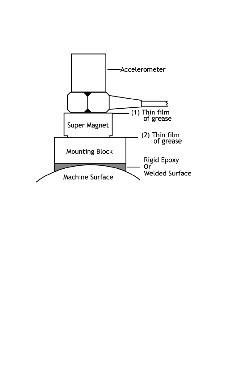
MAGNETIC MOUNTING
be
avoided
by
threading the
It to
the surface.
uncured adhesive from being
removed.
accelerometer
Additional
drawn
up
Magnets are not generally recommended for measurements above
are quite adequate for lower frequency
a
single accelerometer
obvious requirement
that the magnet
is
used
is
that the measurement point must
can stick
to
it.
measurements
to
measure a great number
A
flat magnet with smooth machined surfaces
is
recommended. This allows the
magnet
and perpendicular
to
bond efficiently
surface providing good dynamic transmissibility. For those
magnet does not seat well, it may
magnetic bushing. Note that
Series 300
stainless steel which will not rust and is
most
be
necessary to bond
adhesive
mounting
As with other mounting techniques, a
the dynamic transmissibility when
using
thin film
a magnet.
of
grease
Using horse-shoe (or U-shaped) magnets
popular, should
an example of magnetic
be
restricted
mounting.
to
measurements below
on
curved
Adhesiv
e
or a dummy bolt into the
care should
be
taken to
through the hole when the
5KHz.
They
and can
be
helpful when
of
points. The
be
ferro-magnetic so
mounting
to the
points
a
sizeable ferro-
bushings are made
hole
mounting
where the
of
not fer ro·magnetic.
can
be
used
to
enhance
surfaces, although
1 KHz.
See figure
7-3
for
12
Page 17
13
Figure
7-3.
Magnetic
Mounting
Page 18
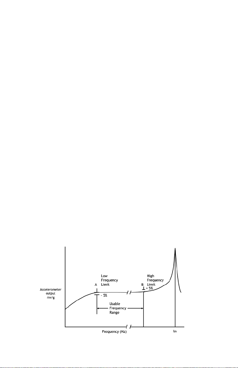
SECTION
Figure 8-1.Typical Frequency Response
Plot
8- SPECIFICATIONS
The
performance specifications for OMEGA accelerometers
defined
well
bulleti
accelerometer
n and
and listed in
the calibration certificate
product for
BASIC SENSITIVITY
OMEGA's
low
impedance accelerometers
output sensitivity groups: 10mV/g
specification represents
course,
100 Hz. Of
within fixed limits.
A ±5%
100mVIg unit
between
verified
specification
95mV/g
at 100
the basic
This limit is
may
and 105mV/g.
Hz and
certificate.
BASIC
FREQUENCY
RESPONSE
frequency response specification
The
much
the
actual sensitivity
ypically
T
this
frequency response specification
specified frequency
response
frequency response specification is indicated
between points A and B.
frequency response specification should
sensitivity
specification.
a unit has an
frequency
within a ±5%
frequencies
is
Th
basic
Exam ple: If
frequency response specification
frequency within
the
100mV/g or as low as
this
section. Refer to the
which is
more information.
are
and
100mV/g. The
the
output
of the
accelerometer
sensitivity
usually
on
this
basic
be
manufactured with a sensitivity which
varies
specified
sensitivity
The actual sensitivity for each
recorded
on the
for an
may
vary
over the
range.
for an
Figure
8·1
depicts a typical wide
accelerometer. The
actual sensitivity
of ±5% the
operating frequency
90mV/g
.
supplied with each
standardized
from
one unit to the next
at ±5%.
means that a
accelerometer's calibration
accelerometer Indicates
useable frequency
is
state
useable
not be
of
95mVIg
actual sensitivity
range
may
are very
appropriate
sales
Into two major
basic sensitivity
as measured at
particular
is
actually
unit is
how
range.
d to be ±5% over a
band
frequency
range
by the
confused with
the
at 100Hz and
at
be as high as
a
a
14
Page 19

15
ACC 101 SPECIFICATIO NS
Power Requirements
2 - 6 mA constant current
@ 24 to 30 VDC
Reference Sensit ivity (±12%)
100 mV/g @ 100 Hz
Frequency Range (±10%)
3 Hz - 5 kH z
Frequency Range (±3dB)
1 Hz - 10 kHz
Amplitude Range
±70 g-pk
Amplitude Linearity
<1%
Temperature Range
-10 to 200 °F (-20 to 95 °C)
Transverse Sensi t ivity
<5%
Shock Lim it
5,000 g-pk
Mounted Resonant Frequency
18 kHz
Output Impedance
100 ohms
Bias Voltage
12 VDC (typ.)
Base Strain (@250 µ-in/in)
<.008 g-pk/µ-in/in (t yp.)
Noise Fl oor (wideband)
250 µg-rms (typ.)
Weight
50 grams
Material
6061 Al
Dimensions
1.5" H x 1" Hex
Connector
Side exit 10' integral c oax ial
cable to BNC
Mounting
1/4-28 removable stud
Mounting Torque
35 in-lb (3.9 N-m)
Page 20

ACC 102A SPECIFICATIO NS
Power Requirements
2 - 6 mA constant current
@ 24 to 30 VDC
Reference Sensit ivity (±10%)
Frequency Range (±5%)
5 Hz - 5 kH z
Frequency Range (±3dB)
2 Hz - 7 kH z
Amplitude Range
±65 g-pk
Amplitude Linearity
Temperature Range
-10 to 200 °F (-20 to 95 °C)
Transverse Sensi t ivity
<5%
Shock Lim it
5,000 g-pk
Mounted Resonant Frequency
Output Impedance
100 ohms
Bias Voltage
12 VDC (typ.)
Base Strain (@250 µ-in/in)
<.001 g-pk/µ-in/in (typ.)
Noise Fl oor (wideband)
300 µg-rms (typ.)
Weight
45 grams
Material
Welded stainless steel wit h
composite polymer
Dimensions
Connector
Side exit 10' integral c oax ial
cable to BNC
Mounting
10-32 captive throughbolt
Mounting Torque
20 in-lb (2.2 N-m)
100 mV/g @ 100 Hz
<1%
18 kHz
1.0" H x 1.2" dia.
16
Page 21

17
ACC 103 SPECIFICATIO NS
Power Requirements
2 - 6 mA constant current @
15 to 30 VDC
Reference Sensit ivity (±5%)
10 mV/g @ 100 Hz
Frequency Range (±5%)
3 Hz - 10 kHz
Frequency Range (±3dB)
1 Hz - 30 kHz
Amplitude Range
±500 g-pk
Amplitude Linearity
<2%
Temperature Range
-40 to 250 °F (-40 to 121 °C)
Transverse Sensi t ivity
<5%
Shock Lim it
5,000 g-pk
Mounted Resonant Frequency
50 kHz
Output Impedance
1000 ohms
Bias Voltage
7 VDC (typ.)
Base Strain (@250 µ-in/in)
Noise Fl oor (wideband)
1500 µg-rms (typ.)
Weight
16 grams
Material
303 stainless steel
Dimensions
.82" H x .5" Hex.
Connector
Side exit 10-32 connector
Mounting
10-32 removable stud
Mounting Torque
20 in-lb (2.2 N-m)
<.003 g-pk/µ-in/in (t yp.)
Page 22

ACC 301A SPECIFICATIO NS
Power Requirements *
2 - 6 mA constant current
@ 15 to 30 VDC
Reference Sensit ivity (±5%) *
10 mV/g @ 100 Hz
Frequency Range (±5%) *
3 Hz - 7 kH z
Frequency Range (±3dB) *
1 Hz - 10 kHz
Amplitude Range *
±500 g-pk
Temperature Range
-40 to 250 °F (-40 to 121 °C)
Transverse Sensi t ivity *
<5%
Shock Lim it *
5,000 g-pk
Mounted Resonant Frequency*
25 kHz (typ.)
Output Impedance *
1000 ohms
Bias Voltage *
7 VDC (typ.)
Base Strain (@250 µ-in/in) *
<.005 g-pk/µ-in/in (typ.)
Noise Floor (wideband) *
1500 µg-rms (typ.)
Weight
14 grams
Material
Dimensions
.85" H x .85" W x 1.1 D
Connector
Side exit 4-pin connector
Mounting
10-32 removable stud
Mounting Torque
* Each axis
Titanium
20 in-lb (2.2 N-m)
18
Page 23

19
ACC 310 SPECIFICATIO NS
Power Requirements
2 - 6 mA constant current
@ 24 to 30 VDC
Reference Sensit ivity (±10%)
Frequency Range (±5%)
5 Hz - 10 kHz
Frequency Range (±3dB)
2 Hz - 20 kHz
Amplitude Range
±70 g-pk
Amplitude Lineari t y
Temperature Range
-40 to 250 °F (-40 to 121
°C)
Transverse Sensi t ivity
<5%
Shock Lim it
5,000 g-pk
Mounted Resonant Frequency
>40 kHz
Output Impedance
100 ohms
Bias Voltage
12 VDC (typ.)
Base Strain (@250 µ-in/in)
.001 g-pk/µ-in/in (typ.)
Noise Fl oor (wideband)
350 µg-rms (typ.)
Weight
68 grams
Material
316L stainless steel
Dimensions
Connector
Top exit 2-pin MIL 5015
Mounting
1/4-28 removable stud
Mounting Torque
35 in-lb (3.9 N-m)
100 mV/g @ 100 Hz
<1%
1.8" H x 7/8" Hex
Page 24

ACC 320 SPECIFICATIONS
Power Requirements
2 - 6 mA constant current
@ 24 to 30 VDC
Reference Sensit ivity (±10%)
100 mV/g @ 100 Hz
Frequency Range (±5%)
5 Hz - 4 kH z
Frequency Range (±3dB)
2 Hz - 12 kHz
Amplitude Range
±70 g-pk
Amplitude Linearity
<1%
Temperature Range
-40 to 250 °F (-40 to 121 °C)
Transverse Sensi t ivity
<5%
Shock Lim it
5,000 g-pk
Mounted Resonant Frequency
>18 kHz
Output Impedance
100 ohms
Bias Voltage
12 VDC (typ.)
Base Strain (@250 µ-in/in)
Noise Fl oor (wideband)
350 µg-rms (typ.)
Weight
155 grams
Material
304L stainless steel
Dimensions
1.05" H x 2.2" L X 1.0" W
Connector
Side exit 2-pin MIL 5015
Mounting
1/4-28 through bolt
Mounting Torque
35 in-lb (3.9 N-m)
<.005 g-pk/µ-in/in (t yp.)
20
Page 25

21
NOTES
Page 26

WARRANTY/DISCLAIMER
OMEGA ENGINEERING, INC. warrants this unit to be free of defects in materials and
workmanship for a period of 13 months from date of purchase. OMEGA’s WARRANTY adds
an additional one (1) month grace period to the normal one (1) year product warranty to
cover handling and shipping time. This ensures that OMEGA’s customers receive maximum
coverage on each product.
If the unit malfunctions, it must be returned to the factory for evaluation. OMEGA’s Customer
Service Department will issue an Authorized Return (AR) number immediately upon phone
or written request. Upon examination by OMEGA, if the unit is found to be defective, it
will be repaired or replaced at no charge. OMEGA’s WARRANTY does not apply to defects
resulting from any action of the purchaser, including but not limited to mishandling, improper
interfacing, operation outside of design limits, improper repair, or unauthorized modification.
This WARRANTY is VOID if the unit shows evidence of having been tampered with or shows
evidence of having been damaged as a result of excessive corrosion; or current, heat, moisture
or vibration; improper specification; misapplication; misuse or other operating conditions
outside of OMEGA’s control. Components in which wear is not warranted, include but are not
limited to contact points, fuses, and triacs.
OMEGA is pleased to offer suggestions on the use of its various products. However,
OMEGA neither assumes responsibility for any omissions or errors nor assumes
liability for any damages that result from the use of its products in accordance
with information provided by OMEGA, either verbal or written. OMEGA warrants
only that the parts manufactured by the company will be as specified and free of
defects. OMEGA MAKES NO OTHER WARRANTIES OR REPRESENTATIONS OF ANY
KIND WHATSOEVER, EXPRESSED OR IMPLIED, EXCEPT THAT OF TITLE, AND ALL
IMPLIED WARRANTIES INCLUDING ANY WARRANTY OF MERCHANTABILITY AND
FITNESS FOR A PARTICULAR PURPOSE ARE HEREBY DISCLAIMED. LIMITATION
OF LIABILITY: The remedies of purchaser set forth herein are exclusive, and the
total liability of OMEGA with respect to this order, whether based on contract,
warranty, negligence, indemnification, strict liability or otherwise, shall not exceed
the purchase price of the component upon which liability is based. In no event shall
OMEGA be liable for consequential, incidental or special damages.
CONDITIONS: Equipment sold by OMEGA is not intended to be used, nor shall it be used: (1)
as a “Basic Component” under 10 CFR 21 (NRC), used in or with any nuclear installation or
activity; or (2) in medical applications or used on humans. Should any Product(s) be used in or
with any nuclear installation or activity, medical application, used on humans, or misused in
any way, OMEGA assumes no responsibility as set forth in our basic WARRANTY / DISCLAIMER
language, and, additionally, purchaser will indemnify OMEGA and hold OMEGA harmless from
any liability or damage whatsoever arising out of the use of the Product(s) in such a manner.
Direct all warranty and repair requests/inquiries to the OMEGA Customer Service Department.
RETURN REQUESTS/INQUIRIES
BEFORE RETURNING ANY PRODUCT(S) TO OMEGA, PURCHASER MUST OBTAIN AN
AUTHORIZED RETURN (AR) NUMBER FROM OMEGA’S CUSTOMER SERVICE DEPARTMENT
(IN ORDER TO AVOID PROCESSING DELAYS). The assigned AR number should then be
marked on the outside of the return package and on any correspondence.
The purchaser is responsible for shipping charges, freight, insurance and proper packaging to
prevent breakage in transit.
FOR WARRANTY RETURNS, please have
the following information available BEFORE
contacting OMEGA:
1. Purchase Order number under which
the product was PURCHASED,
2. Model and serial number of the product
under warranty, and
3. Repair instructions and/or specific
problems relative to the product.
OMEGA’s policy is to make running changes, not model changes, whenever an improvement is possible.
This affords our customers the latest in technology and engineering.
OMEGA is a registered trademark of OMEGA ENGINEERING, INC.
© Copyright 2017 OMEGA ENGINEERING, INC. All rights reserved. This document may not be copied, photocopied,
reproduced, translated, or reduced to any electronic medium or machine-readable form, in whole or in part, without
the prior written consent of OMEGA ENGINEERING, INC.
FOR NON-WARRANTY REPAIRS,
consult
OMEGA for current repair charges. Have the
following information available BEFORE
contacting OMEGA:
1. Purchase Order number to cover the
COST of the repair,
2. Model and serial number of the product, and
3. Repair instructions and/or specific problems
relative to the product.
Page 27

Where Do I Find Everything I Need for
Process Measurement and Control?
OMEGA…Of Course!
Shop online at omega.com
TEMPERATURE
MU
Thermocouple, RTD & Thermistor Probes, Connectors, Panels & Assemblies
MU
Wire: Thermocouple, RTD & Thermistor
MU
Calibrators & Ice Point References
MU
Recorders, Controllers & Process Monitors
MU
Infrared Pyrometers
PRESSURE, STRAIN AND FORCE
MU
Transducers & Strain Gages
MU
Load Cells & Pressure Gages
MU
Displacement Transducers
MU
Instrumentation & Accessories
FLOW/LEVEL
MU
Rotameters, Gas Mass Flowmeters & Flow Computers
MU
Air Velocity Indicators
MU
Turbine/Paddlewheel Systems
MU
Totalizers & Batch Controllers
pH/CONDUCTIVITY
MU
pH Electrodes, Testers & Accessories
MU
Benchtop/Laboratory Meters
MU
Controllers, Calibrators, Simulators & Pumps
MU
Industrial pH & Conductivity Equipment
SM
DATA ACQUISITION
MU
Communications-Based Acquisition Systems
MU
Data Logging Systems
MU
Wireless Sensors, Transmitters, & Receivers
MU
Signal Conditioners
MU
Data Acquisition Software
HEATERS
MU
Heating Cable
MU
Cartridge & Strip Heaters
MU
Immersion & Band Heaters
MU
Flexible Heaters
MU
Laboratory Heaters
ENVIRONMENTAL
MONITORING AND CONTROL
MU
Metering & Control Instrumentation
MU
Refractometers
MU
Pumps & Tubing
MU
Air, Soil & Water Monitors
MU
Industrial Water & Wastewater Treatment
MU
pH, Conductivity & Dissolved Oxygen Instruments
M5097/0117
 Loading...