

Page 1
Bulletin E-24-A
2-27/32
(72.23
1/2 NPT
3-5/32
(80.12)
1-21/32
(42.07)
1-5/8
(41.28)
1/2 male NPT
x 1/8 female NPT
1/8 male NPT
x 7/16-24 female
O-Ring
7/16-24 female
x 1/8 male NPT
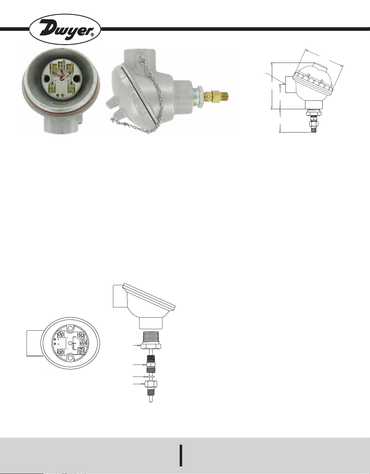
No. A-709 RTD Transmitter Enclosure
Specifications - Installation and Operating Instructions
Shown with optional Series
RTD Temperature Transmitter
PARTS LIST
(1) Enclosure
(1) Enclosure Cover
(1) 1/8˝ male NPT x 7/16-24 male Adapter
(1) 1/8˝ male NPT x 7/16 female Adapter
(1) 1/2˝ male NPT x 1/8˝ female Bushing
(2) M4x8 Socket Cap Screws
(1) 1/4˝ I.D. x 3/8˝ O.D. O-ring
ENCLOSURE ASSEMBLY
1. Insert 1/2˝ male NPT x 1/8˝ female adapter into enclosure
from bottom.
2. Place o-ring inside 7/16-24 female fitting and loosely
assemble it to the 7/16-24 male x 1/8˝ NPT adapter, then
assemble to adapter noted in step #1 as shown in Figure 1.
INSTALLING SERIES 651 RTD TRANSMITTER
1. Use M4x8 screws to attach RTD to enclosure.
2. Feed wiring through 1/2˝ NPT opening.
3. Connect wiring to appropriate terminals on transmitter.
INSTALLING SERIES RTD SENSOR
1. From inside of enclosure, feed tip of RTD sensor through
transmitter (if included) and fitting assembly.
2. Make sure wiring will clear all metal surfaces when cover
is replaced.
3. Lock RTD sensor in place by tightening the two hex fittings outside the enclosure.
4. Use 1/8˝ NPT threads to mount assembled unit in place.
Optional A-345 1/8˝ NPT flange includes a gasket and two
self tapping screws for convenient installation on sheet
metal ducts, etc.
5. Attach RTD sensor wires to transmitter terminals if it is
installed within enclosure, if using a remotely located transmitter , r oute wiring between sensor and transmitter to inside
through the 1/2˝ NPT opening.
6. Replace cover and tighten screws when wiring is complete.
©Copyright 2008 Dwyer Instruments, Inc. Printed in U.S.A. 5/08 FR# 71-440727-10
DWYER INSTRUMENTS, INC.
Figure 1
Phone: 219/879-8000 www.dwyer-inst.com
 Loading...