

Page 1
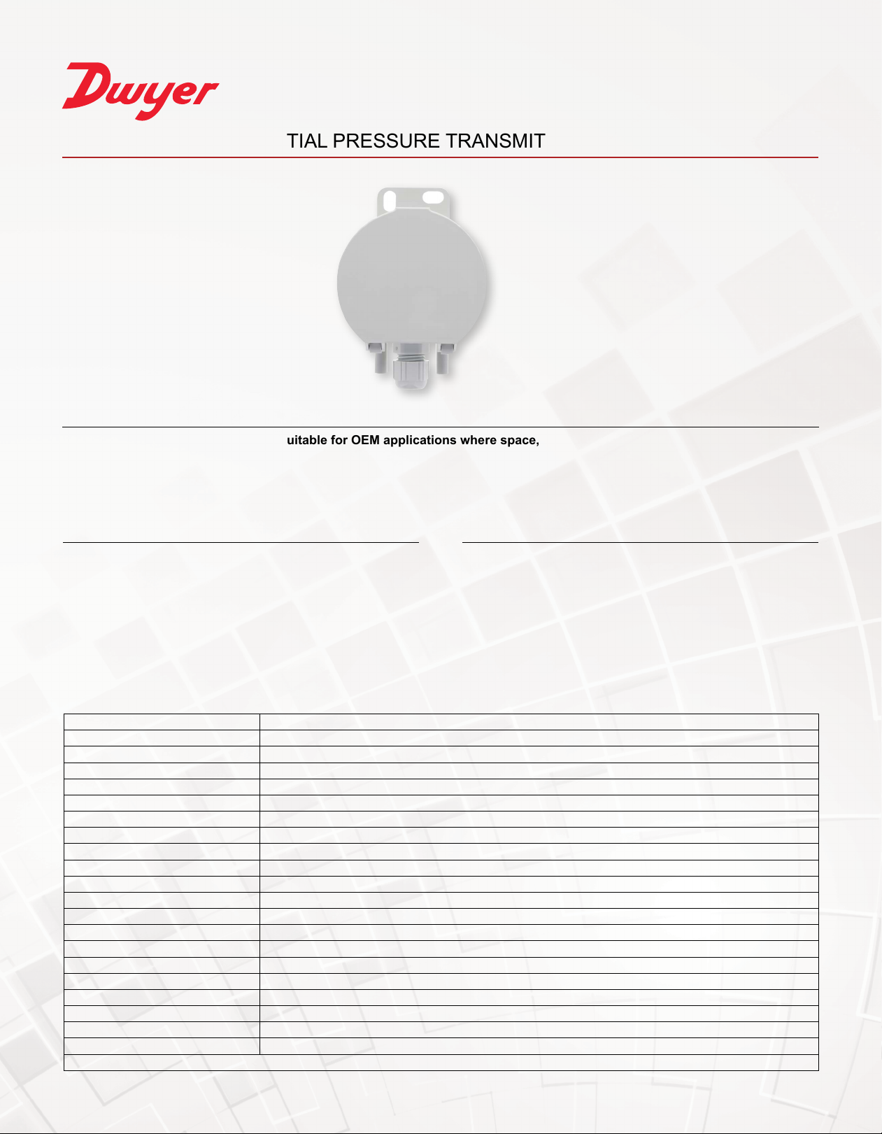
SERIES 685 | DIFFERENTIAL PRESSURE TRANSMITTER
®
BENEFITS/FEATURES
• Cost effective and compact device suitable for OEM applications where space, simplicity, and value are key
• Single button to zero saves maintenance time
• Factory restore to defaults with a long button press
• User-adjustable response time provides versatility for many applications
APPLICATIONS
• Building automation, air-conditioning and clean room technology
• Valve and shutter control
• Filter, ventilator and fan monitoring
• Air-ow control
SPECIFICATIONS
Service Air and non-corrosive gases.
Sensor Type Piezoresistive pressure sensor.
Output Signal 2-wire: 4-20 mA; 3-wire: 0-10 V.
Supply Voltage 2-wire: 18-30 VDC; 3-wire: 18-30 VAC/DC.
Loop Resistance 2-wire: 500 Ω max; 3-wire: ≥ 1 kΩ (≤ 10 mA).
Maximum Current Draw 2-wire: 21 mA; 3-wire: 40 mA.
Accuracy* ≤ ±0.5% RSS (BFSL), ±1 Pa.
Thermal Effects* See model-dependent specications table.
Long-Term Stability* ≤ ±1% RSS per year.
Temperature Limits -4 to 158°F (-20 to 70°C).
Humidity Limits 0 to 95% RH, non-condensing.
Response Time 1 s (default) or 200 ms (user selectable).
Pressure Connections 6 mm hose connection.
Electrical Connection Spring connector for cable and leads up to 1.5 mm
Cable Conduit Cap nut conduit, 15 mm (across ats), made of polyamide.
Mounting Screw fastening with sheet metal screws.
Housing Material ABS.
Housing Dimensions Ø 66 x 28 mm.
Enclosure Rating IP54.
Weight 1.6 oz (46 g).
Compliance CE, UKCA.
*Accuracy specications are based on measurements at 73°F (23°C).
DESCRIPTION
The Series 685 Differential Pressure Transmitter is used to measure
differential pressure and vacuum. The adjustable pressure range and
output signal make it the ideal choice for installers and maintenance
professionals. It has a user-congurable response time via a jumper
and can be mounted in any orientation. Applications include building
automation systems, clean room monitoring, valve and ap control, lter
monitoring, and air ow control. It has an adjustable pressure range, a
single button to zero, and can be reset to factory settings with a long
button press. No additional reference pressure sources or separate
calibration devices are necessary.
2
.
Page 2
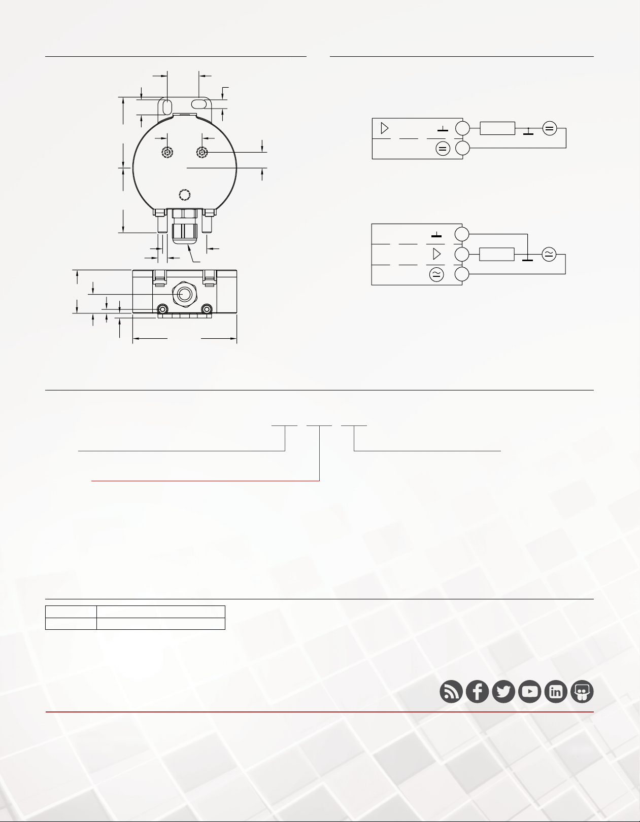
DIMENSIONS WIRING DIAGRAM
0.787 [20.0]
[3.0]
1.083
[27.5]
0.394 [10.0]
2-WIRE
0.217 [5.5]
0.374 [9.5]
0.472
[12.0]
0.098
[2.5]
1.772
[45.0]
1.614
[41.0]
0.236 [6.0]
0.118
0.866 [22.0]
P +
2.598 [66.0]
1.102 [28.0]
15 MM AF
P -
HOW TO ORDER
Use the bold characters from the chart below to construct a product code.
685 -0 -V
4... 20 mA
18... 30 VDC
3-WIRE
GND
0... 10 V
18... 30 VAC
2
LOAD
1
4-20 mA output wiring
3
LOAD
2
1
Voltage output wiring
SERIES
685: Differential pressure transmitter
ELECTRICAL OUTPUT
BLANK: 4-20 mA
-V: 0-10 V
PIPE SIZE
-0: 0 to 1 in w.c.
-1: 0 to 2 in w.c.
-2: 0 to 3 in w.c.
-3: 0 to 5 in w.c.
-4: 0 to 10 in w.c.
-5: 0 to 15 in w.c.
-6: 0 to 20 in w.c.
-7: 0 to 25 in w.c.
-8: 0 to 40 in w.c.
-9: 250 Pa
-10: 750 Pa
-11: 1250 Pa
-12: 2500 Pa
-13: 5000 Pa
ACCESSORIES
Model Description
A-685-DIN DIN rail adapter kit for Series 685
DWYER INSTRUMENTS, LLC
©Copyright 2022 Dwyer Instruments, LLC
Printed in U.S.A. 5/22 DS-685
Important Notice: Dwyer Instruments, LLC reserves the right to make changes to or discontinue any product or service identied in this publication without notice. Dwyer advises its customers to obtain the
latest version of the relevant information to verify, before placing any orders, that the information being relied upon is current.
 Loading...