

Page 1
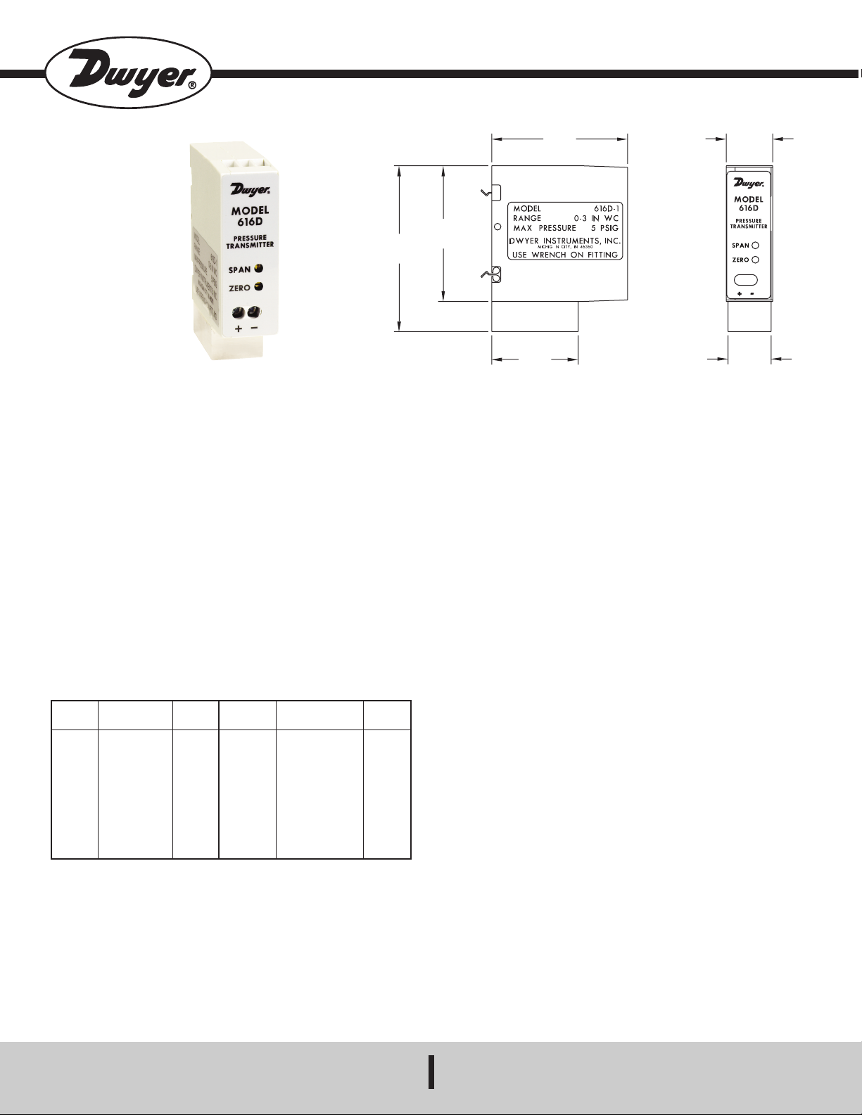
>55.=27
2
-57/64
[
73.42]
2-3/8
[60.33]
1-1/2
[38.10]
2
-3/8
[
60.33]
13/16
[20.64]
3/4
[19.05]
A
".;2.<!*252//.;.7=2*5 ;.<<>;.#;*7<62==.;
"9.,2/2,*=287<D7<=*55*=287*7-9.;*=2707<=;>,=287<
#1. ".;2.< 2//.;.7=2*5 ;.<<>;. #;*7<62==.; senses the
pressure of air and compatible gases and sends a standard 4-20 mA
output signal. The 616D housing is specifically designed to mount on a
35 mm DIN rail in a panel. This mounting style allows for several units to
be mounted closely together reducing required space. A wide range of
models are available factory calibrated to specific ranges as listed in the
chart below. The span and zero controls are for use when checking
calibration. They are not intended for re-ranging to a significantly
different span. Versatile circuit design enables operation in 2-wire
current loops.
For applications requiring direct pressure readings or percent of full span
output, the optional Model A-701 Digital Readout makes an ideal
companion device. It provides a bright red 0.6˝ high, 3-1/2 digit LED
display while supplying power to the Series 616D transmitter. For
additional information on these and other transmitters, see the Dwyer
Instruments, Inc. full line catalog.
".;2.<#;*7<62==.;8-.5<*7-!*70.< "##
*A
;.<<
58 psig
150 psig
150 psig
29 psig
29 psig
2 psig
5 psig
11 psig
8-.5
!*70.
0-3 in w.c.
0-6 in w.c.
0-10 in w.c.
0-20 in w.c.
0-40 in w.c.
0-100 in w.c.
0-200 in w.c.
0-10 psid
0-20 psid
*A
;.<<
2 psig
5 psig
5 psig
11 psig
11 psig
29 psig
29 psig
29 psig
58 psig
8-.5
!*70.
0-30 psid
0-50 psid
0-100 psid
0-12 ft w.c.
0-20 ft w.c.
1.5-0-1.5 in w.c.
5-0-5 in w.c.
10-0-10 in w.c.
" #"
".;?2,.Air and non-combustible, compatible gases.
&.==.-*=.;2*5<Consult factory.
,,>;*,B ±0.25% F.S. at 70°F.
"=*+252=B ±1% F.S./yr.
#.69.;*=>;.262=<20 to 120°F (-6.67 to 48.9°C).
;.<<>;.262=<See chart.
#1.;6*5//.,= ±0.055% F.S./°F (0.099% F.S./°C).
8@.;!.:>2;.6.7=<10-35 VDC (2 wire).
>=9>="207*54 to 20 mA.
).;8*7-"9*7-3><=6.7=<Potentiometers for zero and span.
889!.<2<=*7,.DC: 0-1250 ohms maximum.
>;;.7=87<>69=287DC: 38 mA maximum.
5.,=;2,*5877.,=287<Screw-type terminal block.
;8,.<<877.,=287<1/8˝ female NPT. Accessories included are 2
barbed fittings for 1/8˝ (3.12 mm) and 3/16˝ (4.77 mm) I.D. rubber or
vinyl tubing.
8>7=270;2.7=*=287 Vertical, on a 1.378˝ (35 mm) DIN rail.
&.201=4.8 oz (136 g).
8,*=287
Select a clean, dry mounting location free from excess vibration where
the temperature will remain between 20 and 120°F (-6.7 and 48.9°C).
Distance from the receiver is limited only by total loop resistance. See
Electrical Connections below. The tubing supplying pressure to the
instrument can be practically any length required, but long lengths will
increase response time slightly.
8<2=287
A vertical position, with pressure connections pointing down, is
recommended. That is the position in which all standard models are
spanned and zeroed at the factory. They can be used at other angles,
but final spanning and zeroing must be done while transmitter is in that
alternate position.
;.<<>;.877.,=287<
Two integral barbed tubing connections are provided. They are dualsized to fit both 1/8˝ and 3/16˝ (3.12 and 4.76 mm) I.D. tubing. Be sure
the pressure rating of the tubing exceeds that of the operating ranges.
&(!"#!$#"
'CE#($"
187.E
*AE
@@@-@B.;27<=,86
.6*25E27/8-@B.;6*25,86
Page 2
#!#"
POWER
SUPPLY
10-35 VDC
PRESSURE
TRANSMITTER
RECEIVER
1500
1400
1300
1200
1100
1000
900
800
700
600
500
400
300
200
100
50
Total Receiver Resistance ()
Maximum Value (1250 )
R Max. =
0 5 10 13 15 20 25 30 35 40
L
Vps–10.0
20mA DC
Operating
Region
SPAN AND ZERO
A
DJUST
ELECTRICAL
C
ONNECTIONS
A
$# 8 78= .A,..- <9.,2/2.- <>995B ?85=*0. ;*=270<
.;6*7.7=-*6*0.78=,8?.;.-+B@*;;*7=B@255;.<>5=#12<>72=2<
78=-.<207.-/8;8;?85=<527.89.;*=287
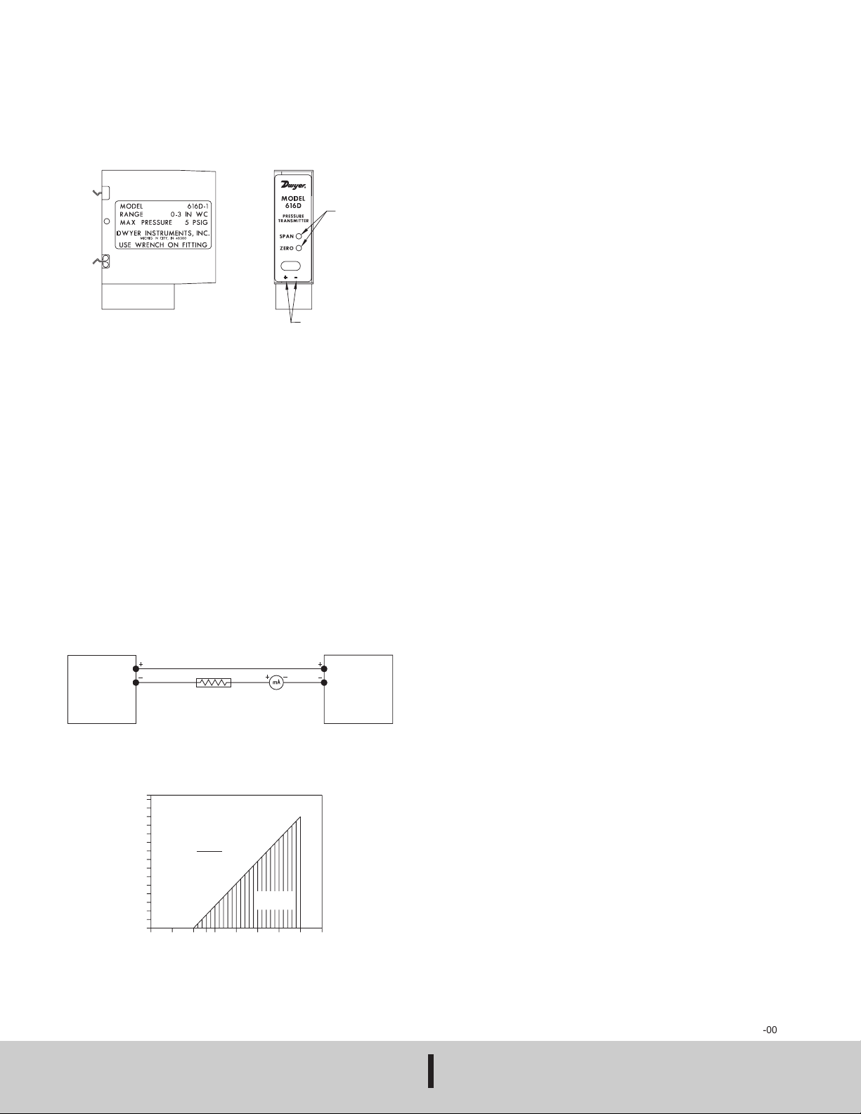
Electrical connections are made to the terminal block located in front of
the transmitter. Terminals are marked + and - (See Figure B below).
20>;.
&2;..70=1
The maximum length of wire connecting transmitter and receiver is a
function of wire size and receiver resistance. Wiring should not
contribute more than 10% of the receiver resistance to total loop
resistance. For extremely long runs (over 1000 feet), choose receivers
with higher resistance to minimize size and cost of connecting leads.
Where wiring length is under 100 feet, hook-up wire as small as 22 AWG
can be used.
*52+;*=2871.,4
Each Series 616D Transmitter is factory calibrated to the range given in
the model chart. To check calibration and adjust if necessary, the
following procedure should be used. For purposes of clarification in these
instructions, range is defined as that pressure which, applied to the
transmitter, produces 20 milliamps of current in the loop. Zero pressure
is always assumed to be 4 milliamps.
1. With the transmitter connected to the companion receiver, insert an
accurate milliameter in series with the current loop. The milliameter
full scale range should be 30 mA or greater.
2. Connect a controllable pressure source to one leg of a tee with the
other two legs connected to the high pressure port of the transmitter
and the third leg to an accurate test gage or manometer, in an
appropriate range. The low pressure port should be vented to
atmosphere. Calibration must be performed with the unit in the same
position in which it will be mounted.
3. Apply electrical power to the unit and allow it to stabilize for 10
minutes.
4. With no pressure applied to the transmitter, adjust ZERO control so
that loop current is 4 mA. See Figure B.
5. Apply full range pressure and adjust loop current to 20 mA using
SPAN control. See Figure B.
6. Relieve pressure and allow transmitter to stabilize for 2 minutes.
7. Zero and span controls are slightly interactive, so repeat steps 4
through 6 until zero and full range pressures consistently produce
currents of 4 and 20 mA respectively.
8. Remove the milliameter from the current loop and proceed with final
installation of the transmitter and receiver.
&2;.9.;*=287
An external power supply delivering 10-35 VDC with minimum current
capability of 40 mA DC (per transmitter) must be used to power the
control loop. See Figure C for connection of the power supply, transmitter
and receiver. The range of appropriate receiver load resistance (RL) for
the DC power supply voltage available is expressed by the formula and
graph in Figure D. Shielded two wire cable is recommended for control
loop wiring. If grounding is required, use the negative side of the control
loop after the receiver. Otherwise, in 2-wire operation it is not necessary
to observe polarity of control loop connections.
&2;.877.,=287<
20>;.
8@.;">995B%85=*0.D%@2;.
%85=*0.79>=
Series 616D Transmitters can be easily adapted for receivers requiring
1-5 or 2-10 VDC inputs. Insert a 249 ohm, (1-5 VDC) or 499 ohm (2-10
VDC) resistor of the proper power rating in series with the current loop
but in parallel with the receiver input. Locate this resistor as close as
possible to the input. Because resistor accuracy directly influences
output signal accuracy, we recommend use of a precision ±0.1%
tolerance resistor to minimize this effect.
$# !%!"##
An advantage of the standard 4-20 mA DC output signal produced by the
Series 616D Transmitter is that any number of receivers can be
connected in series in the current loop. Thus, an A-701 Digital Readout,
an analog panel meter, a chart recorder, process controlling equipment
or any combination of these devices can be operated simultaneously.
The only requirement is that each component be equipped for a standard
4-20 mA input and the proper polarity of the input connections be
observed when inserting the device in the current loop. If any of the units
display a negative or downscale reading, the signal input leads are
reversed.
#
Upon final installation of the Series 616D Differential Pressure
Transmitter and the companion receiver, including the A-701 Digital
Readout, no routine maintenance is required. A periodic check of the
system calibration is recommended following the procedures explained
under Calibration Check. The Series 616D Transmitter is not field
serviceable and should be returned, freight prepaid, to the factory if
repair is required. Please enclose a description of the problems
encountered plus any available application information. The A-701
should be returned directly to its manufacturer for service. See the A-701
instructions for address.
©Copyright 2015 Dwyer Instruments, Inc.
&(!"#!$#"
'CE#($"
20>;.
Printed in U.S.A. 8/15 FR# 443269-00 Rev. 3
187.E
*AE
@@@-@B.;27<=,86
.6*25E27/8-@B.;6*25,86
 Loading...