

Page 1
TM
1. INSTALLATION AND START-UP
1. Install the instrument at the DIN rail
2. Connect the power supply (see section 5)
• see section 7.1 for an explanation on ‘normal mode’ of operation
3.Accessthe‘congurationsystem’(seesection8)
• remove the output signal terminal
• make sure there are no dangerous voltages at the input signal terminals (in case of
doubt, remove also the two input signal terminals)
• open the front cover
•locatethe‘congurationdigits’
• locate the ‘UP’ (5) and ‘SQ’ (<) keys
4.Conguretheinputsignal(seesection7)
•choosethedesiredcongurationcodefortheinputsignal(seesection6)
• introduce the code at the instrument (see section 7.2)
5.Conguretheoutputsignal(seesection7)
•verifytheactualcongurationandmodifyifrequired(seesection7.3)
6.Blockaccesstothe‘congurationsystem’(seesection8)
• remove the output signal terminal (if it was placed)
• close the front cover
• connect the output signal terminal
•conrmthatthefrontcovercannotbeopened
• connect the two input signal terminals (if they were removed)
7. Connect the output signal (see section 5)
8.Connecttheinputsignal(seesection5)
2. MATERIAL INCLUDED
The instrument is provided with the following elements :
• 1 x instrument DR-I3P
• 4 x plug-in screw terminals, connected to the instrument
• 1 x Quick installation guide
3. ADDITIONAL DOCUMENTATION
To view the DR-I3P spec sheet and manuals visit
us at http://www.omega.com/...
4. HOW TO ORDER
Model No. Description
DR-I3P
Isolated signal converter with universal
power supply
QUICK INSTALLATION GUIDE · DR-I3P
Page 1/2
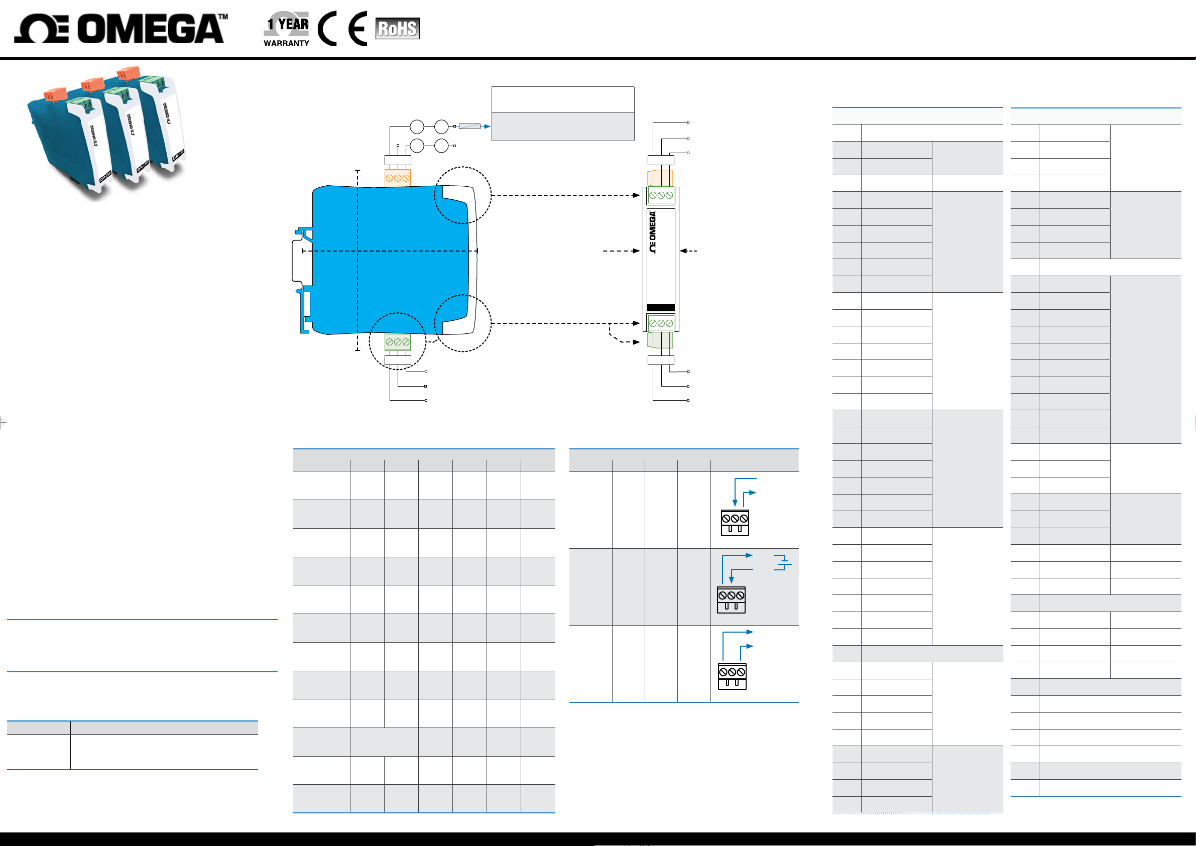
5. CONNECTIONS 6. INPUT SIGNAL - CONFIGURATION CODES
Powerfrom18to265Vac/dcisolated
(Freq.45/65Hz,consumption<1.5W,overvoltagecat.2).
Protection fuse for power supply:
~
~ -
ABC
108 mm
(4.25’’)
fuse
+
•400 mAtime-lagforpower<50 Vac/dc
•250 mAtime-lagforpower50to265 Vac/dc
OUTPUT SIGNAL (789)
see ‘Table 2’
106 mm
(4.17’’)
INPUT SIGNAL (123 456)
see ‘Table 1’
1 2 3
Standard(35 mm)DIN
rail mount
Pt+, Ni+, Ntc+, Resistance+
Thermocouple +,Pt1003rdwire
Thermocouple -,Pt-,Ni-,Ntc-,Resistance-
Table 1 | INPUT signal connections
INPUT signal Input terminal
1 2 3 4 5 6
4/20 mApassive mA- Vexc
4/20 mAactive mA- mA+
0/10 Vdc common +Vdc
0/10 Vdc
with Vexc
Potentiometer Pot.- Potent. Pot.+
Resistance Res- Res+
NTC NTC- NTC+
Thermocouple tc- tc+
Pt100 (3 wires) Pt-
Pt100 (2 wires)
Pt1000, Pt500 Pt- Pt+
Ni100, Ni500,
Ni1000
(short. 1 and 2)
Ni- Ni+
Pt-
(3rd wire)
Pt-
common +Vdc Vexc
Pt+
Pt+
789
22.5mm
(0.89’’)
DR-I3P
456
Table 2 | OUTPUT signal connections
OUTPUT
signal
4/20 mA
active
4/20 mA
passive
0/10 Vdc common +Vdc
Output terminal Connections
7 8 9
mA-
(in)
mA+
(out)
mA-
(in)
Common 0V
Signal4/20 mA
Signal0/10 Vdc
(or passive mA output)
(mA current return)
(or active mA output)
Vexc(+15 Vdc),Pot.+(5 Vdc)
mA, Vdc, Potentiometer
Common, Pot.-
mA-
mA+
mA+
(out)
789
mA+
mA-
789
common
+Vdc
789
Table 3 | Input signal - Conguration codes
Code Input signal range
00to09 [no function assigned]
10 4/20 mA
11 0/10 Vdc
12 0/100 % Potentiometer
13 0/100 KOhm
14 0/50 KOhm
15 0/25 KOhm
16 0/10 KOhm
17 0/5 KOhm
18 0/2.5 KOhm
19 0/1200 ºC
20 0/1000 ºC
21 0/800 ºC
22 0/600 ºC
23 0/450 ºC
24 0/300 ºC
25 0/150 ºC
26 0/1350 ºC
27 0/1000 ºC
28 0/800 ºC
29 0/600 ºC
30 0/450 ºC
31 0/300 ºC
32 0/150 ºC
33 0/1300 ºC
34 0/1000 ºC
35 0/800 ºC
36 0/600 ºC
37 0/450 ºC
38 0/300 ºC
39 0/150 ºC
40 [no function assigned]
41 0/900 ºC
42 0/600 ºC
43 0/450 ºC
44 0/300 ºC
45 0/150 ºC
46 0/400 ºC
47 0/300 ºC
48 0/200 ºC
49 0/100 ºC
Process
Resistance
Thermocouple J
ThermocoupleK
Thermocouple N
Thermocouple E
Thermocouple T
Table 3 | Input signal - Conguration codes
Code Input signal range
50 0/1750 ºC
51 0/1500 ºC
Thermocouple R
52 0/1200 ºC
53 0/900 ºC
54 0/1750 ºC
55 0/1500 ºC
Thermocouple S
56 0/1200 ºC
57 0/900 ºC
58 [no function assigned]
59 0/700 ºC
60 0/600 ºC
61 0/500 ºC
62 0/400 ºC
63 0/300 ºC
64 0/200 ºC
65 0/100 ºC
66 -50/+50 ºC
67 -100/+100 ºC
68 -200/+200 ºC
69 0/630 ºC
71 -150/150 ºC
72 0/630 ºC
74 -150/150 ºC
75 -60/180 ºC Ni100
76 --- ---
77 -60/180 ºC Ni1000
78to79 [no function assigned]
80 -50/50 ºC NTC
81 0/90 ºC NTC
82 -50/50 ºC NTC(44006)
83 0/90 ºC NTC(44006)
84to94 [no function assigned]
95 ‘Password’ function
96 Pt100‘Alpha’(01=0.0385,02=0.0390)
97 Factorydefaultconguration
98 Firmware version
99 [no function assigned]
--- Exit de menu and discard changes
Pt100
Pt50070 0/300 ºC
Pt100073 0/300 ºC
(R25=10K,β=3500)
(R25=10K,β=3500)
MQSxxxx_0121
Page 2
QUICK INSTALLATION GUIDE · DR-I3P
TM
Page 2/2
7. CONFIGURATION AND OPERATION
7.1 OPERATION IN ‘NORMAL MODE’
Whenthepowersupplyisconnected,theinstrument:
•activatesthe‘congurationdigits’,anddisplaysthecodefortheactualinputsignal
range
•activatesthedecimalpoint(ash),showingtheactualoutputsignalrange
• the instrument is in ‘normal mode’ of operation
‘Eco’ function (‘conguration digits’ are automatically powered off)
Ifthere isnointeractionfromthe operatorfor 60seconds,the instrumentpowersoff
the‘congurationdigits’.Thedecimalpointremainsactive(ashing),indicatingthatthe
instrument is working correctly.
Topoweronthe‘congurationdigits’,pressoneofthefrontkeys‘SQ’ (<) or ‘UP’ (5).
Thiswillpoweronthe‘congurationdigits’andactivatethe‘normalmode’ofoperation.
7.2 INPUT SIGNAL CONFIGURATION
Withtheinstrumentin‘normalmode’ofoperation(seesection7.1),pressthe‘SQ’ (<)
keyfor1second.Thehorizontalledslightfrombottomtotop.Whentheupperledlights,
theinstrumentactivatesthe‘congurationmode’.
Ifthekeyisreleasedbeforeactivatingthe‘congurationmode’,thehorizontalleds
light downwards from top to bottom, and the instrument returns to ‘normal mode’ of
operation.Insidethe‘congurationmode’thedecimalpointisnotactive.
Insidethe‘congurationmode’,the‘congurationdigits’indicatethecodefortheactual
inputsignalrange(seesection6foralistofcodes).Pressthe‘UP’(5)keytoincrease
the code number.
• press once to increase the value in ‘+1’
• maintain the key pressed to automatically increase the value
Whenthedesiredcodeisreached,pressthe‘SQ’(<)key.Theleds lighta roundshape
whilethenew congurationisstored, andtheinstrument returns to‘normalmode’of
operation.
Whenexitingthe ‘congurationmode’without changes (‘rollback’ activation, ‘inactive
code’selection, etc)thehorizontalleds light downwardsfromtop tobottom,andthe
instrument returns to ‘normal mode’ of operation.
‘Rollback’ function
If there is no interaction from the operator for 30 seconds, the instrument exits the ‘con-
gurationmode’andreturnsto‘normalmode’ofoperation,discardingchanges.
7.3 OUTPUT SIGNAL CONFIGURATION
How to identify the congured output signal
Theconguredoutputsignalisidentiedwiththeactivedecimalpoint:
•activedecimalpointtotheright,for4/20 mAoutput
•activedecimalpointtotheleft,for0/10 Vdcoutput
Output 0/10 Vdc
(left decimal point)
How to congure the output signal
Withtheinstrumentin‘normalmode’ofoperation(seesection7.1),pressthe‘SQ’ (<)
and ‘UP’ (5) keys at the same time.
•thehorizontalledslightfrombottomtotop
• when the upper led lights, the actual decimal point position is displayed
• after 1 second, the decimal point will switch position
•releasethe two keys,theleds light aroundshapewhile the newcongurationis
stored, and the instrument returns to ‘normal mode’ of operation
•ifthekeysarereleasedbeforethenewcongurationisstored,thehorizontalleds
will light downwards from top to bottom, and the instrument returns to ‘normal mode’
of operation.
Connecttheoutputterminalsaccordingtotheoutputsignalcongured.
Output 4/20 mA
(right decimal point)
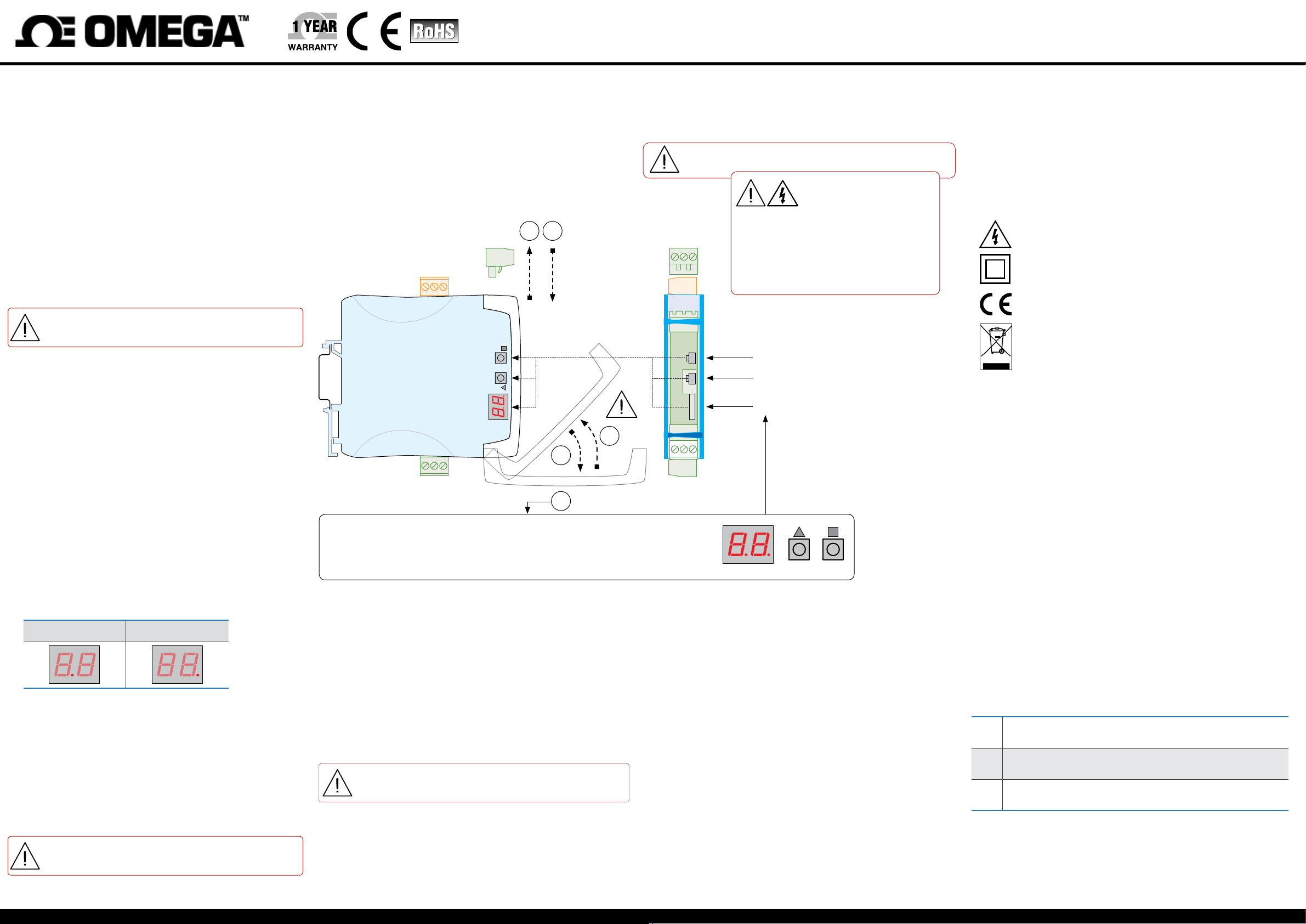
8. CONFIGURATION SYSTEM
1. Remove the output signal terminal
• check that there are no dangerous voltages at the input signal terminals (in case of
doubt, remove also the two input signal terminals)
2.Openthefrontcover
3.Conguretheinstrument
•locatethe‘congurationdigits’
• locate the ‘UP’ (5) and ‘SQ’ (<) keys
4. Close the front cover
• remove the output signal terminal (if it was previously placed)
51
UP SQ
4
2
3
‘CONFIGURATION SYSTEM’
•the‘congurationdigits’indicatetheactiveinputsignalrange(seesection6)
• keys ‘UP’ (5) and ‘SQ’ (<)toconguretheinstrument(seesection7)
• the decimal point position indicates the active output signal range (see section 7.3)
9. MENU ‘TOOLS’
The ‘Force Low’ (‘FL’) and ‘Force High’ (‘Fh’) functions inside the ‘tools’ menu, temporarily
force the output signal to the low and high levels of the output signal range selected. These
tools allow to validate the function of remote elements connected to the instrument output.
• ‘Force Low’ (‘FL’)forcestheoutputsignaltotheminimum(4 mAor0 Vdc).The‘FL’ash
message indicates that the function is active. Press any key to deactivate and return to
the ‘Force Low’ (‘FL’) menu entry.
• ‘Force High’ (‘Fh’)forcestheoutputsignaltothemaximum(20 mAor10 Vdc).The‘Fh’
ashmessageindicatesthatthefunctionisactive.Pressanykeytodeactivateandreturn
to the ‘Force High’ (‘Fh’) menu entry.
How to access the ‘tools’ menu
Withtheinstrumentin‘normalmode’ofoperation(seesection7.1),pressthe‘UP’ (5) key
for1second.Thehorizontalleds lightfrombottomto top.Whenthe upperledlights,the
instrument activates the ‘tools’ menu activates.
Ifthekeyisreleasedbeforeactivatingthe‘tools’menu,thehorizontalledslight
downwards from top to bottom, and the instrument returns to ‘normal mode’ of
operation. Inside the ‘tools’ menu the decimal point is not active.
Insidethe‘tools’menu,the‘congurationdigits’indicatethecodeoftherstfunctionavailable.
• press the ‘UP’ (5) key to move to the next function
• press the ‘SQ’ (<) key to activate the function
To exit the ‘tools’ menu, press the ‘UP’ (5) key until the parameter ‘- -’ appears. Press the ‘SQ’
(<)key.Thehorizontalledslightdownwardsfromtoptobottomandtheinstrumentreturns
to ‘normal mode’ of operation (or wait for the automatic ‘rollback’ (30 seconds)).
5. Connect the output signal terminal
• when connected at place, check that the front cover can not be opened
• if previously removed, connect the two input signal terminals
Whencorrectlyconnected,theoutputsignalterminalpreventsthefrontcover
from opening.
Opening the front cover reduces the security level of the operator. If dangerous
terminals, remove both input signal terminals before opening
thefrontcover.Whenthefrontcoverisopen:
• isolation between power supply and ac
cessible parts and is reduced to ‘basic’ level.
• isolation between input signals and accessible parts is temporarily disabled.
Theoperationmustbeperformedbyqualiedoperators.
Key‘SQ’ (<)
Key‘UP’ (5)
‘Conguration digits’
‘Conguration digits’
voltages are connected to any of the input
-
UP SQ
10. PASSWORD CONFIGURATION
Deneapasswordtopreventaccessto‘congurationmode’and‘tools’menutounauthorizedoperators.
•accessthe‘congurationmode’
•accesscode‘95’andpresskey‘SQ’ (<)
•the‘congurationdigits’indicatecode‘00’ashing
• press key ‘UP’ (5) to select the desired code (for example, ‘73’)
• press key ‘SQ’ (<) to validate
•themenureturnstocode‘95’
•exit‘congurationmode’validatingchanges(accessthe‘--’entryandpress‘SQ’ (<))
• to exit without validating changes, wait for the automatic ‘rollback’ (30 seconds)
Oncethepasswordisapplied,whenakeyispressed,the‘congurationdigits’ashwith
code ‘00’. Enter the ‘password’ code to grant access (code ‘73’ in the previous example).
How to deactivate the password
Todeactivatethepassword,accesscode‘95’,selectvalue‘00’,andvalidatechanges.
11. REGULATIONS
This instrument conforms to the actual CE regulations. For a copy of the ‘CE declaration of
conformity’ see section 3. Applicable regulations are :
Security regulations EN-61010-1(‘Fixed’equipment,‘Permanentlyconnected’.‘Double’isolation.Overvoltagecategory2).
Electromagnetic compatibility regulations EN-61326-1
This instrument does not provide a general mains switch and will start operation as soon as
power is connected. The instrument does not provide protection fuse, and the fuse must be
added during installation. Instrument designed to be DIN rail mounted, inside a cabinet, protected from direct impacts.
Risk of electrical shock. Instrument terminals can be connected to dangerous
voltage.
Instrumentprotectedwithdoubleisolation.Noearthconnectionrequired.
Instrument conforms to CE rules and regulations.
Accordingtodirective2012/19/EU,electronicequipmentmustberecycledina
selective and controlled way at the end of its useful life.
12. FACTORY CONFIGURATION
Inputsignal 4/20 mA [10]
Outputsignal 4/20 mA [xx.]
Passwords disabled [00]
‘Alpha’ 0.0385 [01]
Display code [10.]
Toreturntofactorydefaultparameters,selectcode‘97’andactivatevalue‘01’.
•accessthe‘congurationmode’
•accesscode‘97’andpresskey‘SQ’ (<)
•the‘congurationdigits’indicatecode‘00’ashing
• press key ‘UP’ (5) to change to ‘01’
• press key ‘SQ’ (<)
•theledslightaroundshapewhilethenewcongurationisstored,andtheinstrument
returns to ‘normal mode’ of operation
•the‘congurationdigits’indicatecode‘10.’andthedefaultfactorycongurationisnow
active
13. ERROR CODES
Table 4 | Messages and errors
‘Hardwareunderrange’.Inputsignalisbelowtheminimumreadablesignal.Output
E1
signalistheminimumavailable0 Vdc,0 mA.Possiblesensorbreak.
‘Hardwareoverrrange’.Inputsignalisabovethemaximumreadablesignal.Output
E2
signalisthemaximumavailable10.5 Vdc,20.5 mA.Possiblesensorbreak.
‘Password error’. If ‘password’ function is active, the password code entered is not
E3
correct.
Theerrorcodeisshownashingondisplay.Theerrorcodeisnotvisibleinside‘conguration
mode’ or inside the ‘tools’ menu. The error code remains active on display until the problem
thatcausedtheerrorissolved.Incaseofmultipleerrorcodes,solvetherstproblemtosee
the next active error code.
 Loading...