

Page 1
Linear Thermistor
Components and Probes
OL-705-PP air probe shown with
Model 5830, sold separately.
Following is a description of why these networks
produce linear information. The equation for a voltage
divider network, consisting of R and R0 in series, is:
where E
thermistor, and E
is the voltage drop across R. If R is a
out
out
the total curve will be essentially non-linear and of a
general “S” shape, with linear or nearly linear portions
near the ends and in the center.
E
= Ein
out
R
R + R
0
is plotted versus temperature,
D
Linear Response Components
For applications requiring thermistors with linear
response to temperature change, OMEGA offers
linear components. These unique devices consist of
a thermistor composite for temperature sensing and
an external resistor composite for linearizing.
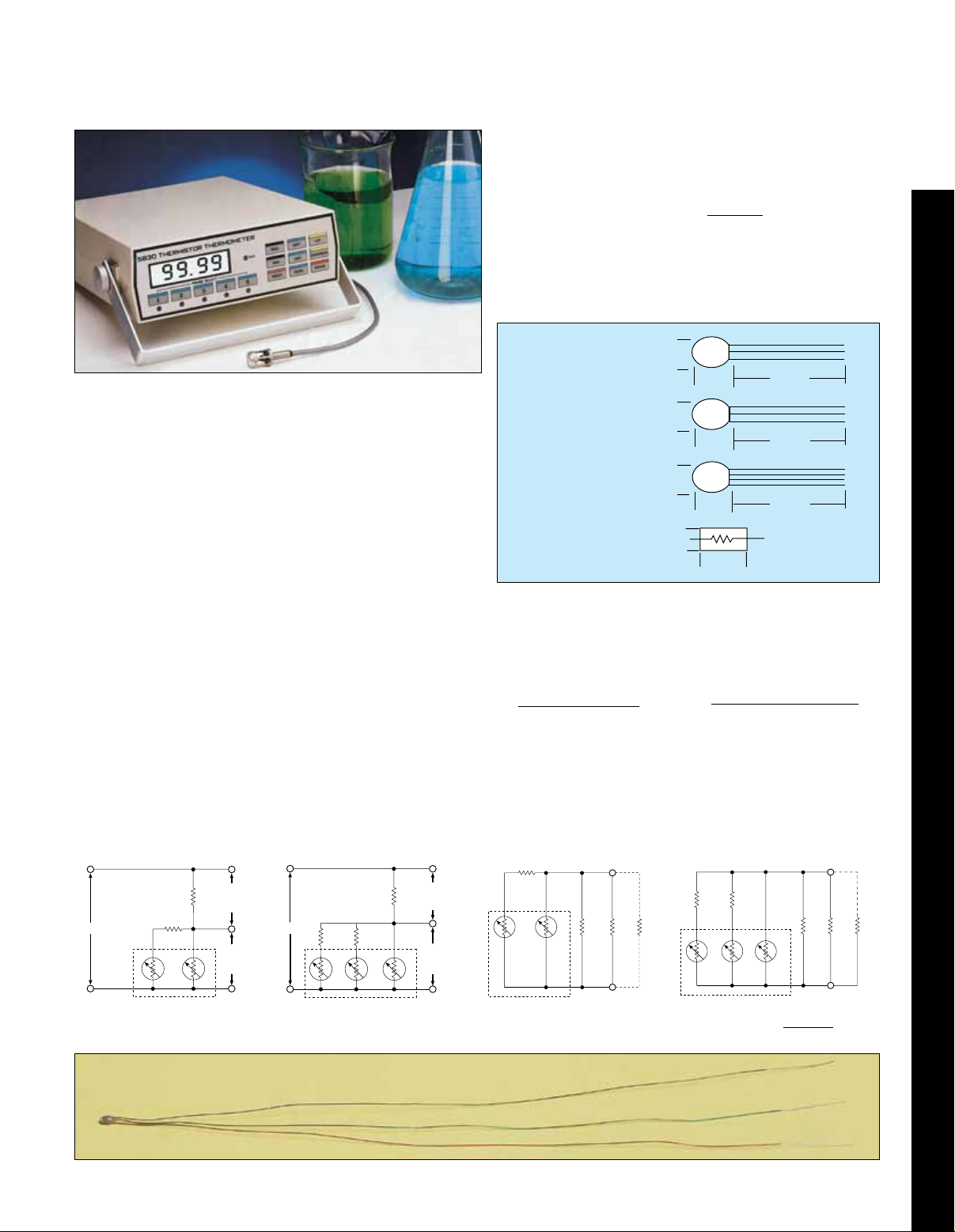
Thermistor composites 44018 and 44019 each contain
two thermistors packaged in a single sensor (Figures
1A and 1B). Thermistor composite 44020 contains three
thermistors packaged in a single sensor (Figure 1C).
Resistor composites for use with 44018 and 44019
thermistor composites consist of two metal film resistors of
the size shown in Figure 2. Resistor composites for use
with the 44020 thermistor composite consist of three of
the same type metal film resistors.
Linear components are manufactured with different
values for different temperatures ranges. When they
are connected in networks shown in Figures 3 (A and
B) and 4 (A and B), they produce a varying voltage or
resistance which is linear with temperature.
One of the basic network manifestations is a voltage
divider as in Figure 3A for components other than #44212,
and as shown in Figure 3B for component #44212. The
area within the dashed lines represents the thermistor
composite. The network hookup for linear resistance
versus temperature is shown in Figure 4A for linear
components except #44212, and in Figure 4B for #44212.
Linear Voltage vs. Temperature
E
out
1
Positive
Slope
E
in
R2R
T
1
T
2
E
out
Negative
Slope
Figure 3B
E
in
Figure 3A
R
R
2
T
1
Note: Model 5830 precision benchtop thermometer
includes linearized circuity.
3
T
2
E
R
out
Positive
1
Slope
E
out
Negative
Slope
T
3
Figure 1A
Thermistor
Composite 44018
Figure 1B
Thermistor
Composite 44019
Figure 1C
Thermistor
Composite 44020
Figure 2
Metal Film
Resistor
2.0 mm
(0.08")
Max.
2.8 mm
(0.110")
Max.
3.1 mm
(0.125")
Max.
2.5 mm
(0.100")
Max.
3.8 mm
(0.150)
Max.
3.8 mm
(0.150)
Max.
7.1 mm
(0.28'')
Max.
6.8 mm
(0.27")
Max.
150 mm
(6") Nom.
150 mm
(6") Nom.
150 mm
(6") Nom.
0.63 mm D
(0.025")
If R is modified by the addition of other thermistors and
resistors, linearity of the center section of the curve,
where sensitivity is greatest, can be extended to cover
a wide range of temperatures. This section follows the
general equation for a straight line, y = mx + b or in
terms of a linear component:
For Voltage Mode
E
= ±MT + b Rt = MT + b
out
For Resistance Mode
where M is slope where M is slope
in volts/ °T, in ohms/°T,
T is temperature T is temperature
in °C or °F, and in °C or °F, and
b is the value of b is the value of the
E
when T = 0° total network resistance,
out
Rt, in ohms when T =
Linear Resistance vs. Temperature
R
2
R2R
3
R
x RL1
1
– R
1
R
1
1
R
T
1
1
T
2
Figure 4A
RL1 may be any value as long as a new R1 value
*
(R1A) is selected to satisfy the relationship:
RL
R
1
*
T1T2T
Figure 4B
R1A =
3
R
RL
RL
1
*
D-42
Page 2
Sensitivity is 400 times greater
than an IC thermocouple.
Thermistor values as high as
30 mV/°C are common. In addition,
output voltage can be applied to
a recorder or digital voltmeter to
produce a precise, sensitive,
direct reading thermometer.
In other situations,
it is frequently desirable to have
thermistor composite temperature
sensors at more than one
location. When this is required,
it is not necessary to have a
separate resistor composite for
each thermistor composite. It is
possible to multiplex any number of
thermistor composites through
a single resistor composite for
greater design flexibility
Multiplexing
The 44018 thermistor composite
is used in four of the linear
components. The part that changes
in each component is the resistor
composite, which determines the
temperature range. Therefore,
the 44018 thermistor composite
can be used over the entire -30 to
100°C temperature range by simply
changing resistor composites.
Its accuracy and interchangeability
over the full range is ±0.15°C.
It is not mandatory that OMEGA®
resistor composites be used with the
44018 thermistor composite. Any
0.1% resistors of the proper values
and with a temperature coefficient of
30 PPM or less may be substituted.
To Order
Thermistor Resistor
Linear Kit
Model No. Model No. Model No.
44201 44018 44301
44202 44018 44302
44203 44018 44303
44204 44018 44304
44211A 44019 44311A
44212 44020 44312
See the next page for more information.
Ordering Examples: 44203, linear kit, 44018, dual thermistor composite plus 44303, resistor
composite sensor.
44202, linear kit, 44018, dual thermistor composite plus 44302, resistor composite sensor.
†
Composite Composite
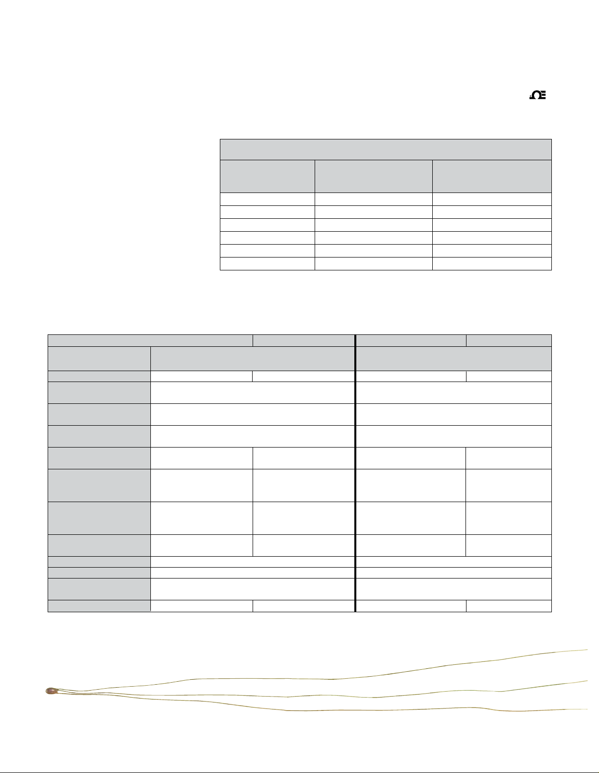
Component Specifications
°C °F °C °F
† Linear Components
Kit Model No. 44201 44202
Range 0 to 100°C 32 to 212°F -5 to 45°C 23 to 113°F
Thermistor Composite
Model No. 44018 44018
Resistor Composite
Model No. 44301 44302
Resistor R
Composite Values R
Thermistor Accuracy ±0.15°C ±0.27°F ±0.15°C ±0.27°F
& Interchangeability -30 to 100°C -22 to 212°F -30 to 100°C -22 to 212°F
E0 Positive Slope E
= E
out
(+0.0053483 E
+0.13493 E
E0 Negative Slope E
= E
out
(-0.0053483 E
+0.86507 E
Resistance Mode Rt = Rt = Rt = Rt =
(-17.115) T +2768.23 (-9.508) T +3072.48 (-32.402) T +4593.39 (-18,001) T +5169.42
*Ein MAX 2.0 Volts 3.5 Volts
*IT MAX 625 µA 615 µA
***Load Resistance
Minimum R.L. 3 MΩ 10 MΩ
Linearity Deviation ±0.216°C ±0.388°F ±0.065°C ±0.12°F
* Ein Max and *IT Max values have been assigned to control thermistor self-heating errors so they do not enlarge the component error band;
i.e., the sum of the linearity deviation plus the probe tolerances. The values were assigned using a thermistor dissipation constant of 8MW/°C
in stirred oil. If better heat-sink methods are used or if an enlargement of the error band is acceptable, Ein Max. and IT Max values may be
exceeded without damage to the thermistor probe.
*** See Figure 1, example 1 on typical linear component application on next page.
† † Kit includes thermistor composite and resistors.
= 3200 Ω, R1 = 5700 Ω,
1
= 6250 Ω R2 = 12000 Ω
2
= E
) T (+0.00297127 Ein) T (+0.0056846 Ein) T (+0.00315851 Ein) T
in
+0.03985 Ein +0.194142 Ein +0.093083 E
in
) T (-0.00297127 Ein) T (-0.0056846 Ein) T (-0.00315851 Ein) T
in
+0.96015 Ein +0.805858 Ein +0.906917 E
in
out
= E
out
= E
out
= E
out
out
out
=
in
=
in
D-43
Page 3
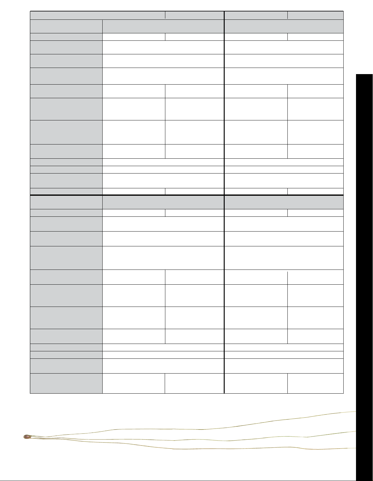
°C °F °C °F
Linear Components
Kit Model Number† 44203 44204
Range -30 to 50°C -22 to 122°F -2 to 38°C +30 to 100°F
Thermistor Composite
Model Number 44018 44018
Resistor Composite
Model Number 44303 44304
Resistor R1 = 18,700 Ω R1 = 5700 Ω
Composite Values R2 = 35,250 Ω R2 = 12,400 Ω
Thermistor Accuracy ±0.15°C ±0.27°F ±0.15°C ±0.27°F
& Interchangeability -30 to 100°C -22 to +212°F -2 to +38°C -22 to +212°F
E
= E
out
= E
out
= E
out
out
=
(+0.0067966 Ein) T (+0.00377588 Ein) T (+0.00563179 Ein) T (+0.0031289 Ein) T
E0 Positive Slope +0.34893 Ein +0.228102 Ein +0.192439 Ein +0.09232 E
E
= E
out
= E
out
= E
out
out
in
=
(-0.0067966 Ein) T (-0.00377588 Ein) T (-0.00563179 Ein) T (-0.0031289 Ein) T
E0 Negative Slope +0.65107 Ein +0.771898 Ein +0.807563 Ein +0.90768 E
in
Resistance Mode Rt = (-127.096) T Rt = (-70.608) T Rt = (-32.1012) T Rt = (-17,834) T
+12175 +14435 +4603.1 +5173.8
Ein MAX* 3.0 Volts 4 Volts
IT MAX***
475 µA 685 µA
Load Resistance
Minimum R.L.*** 10 MΩ 10 MΩ
Linearity Deviation ±0.16°C ±0.29°F ±0.03°C ±0.055°F
Linear Components
Kit Model Number† 44211A 44212
Range -55 to 85°C -67 to 185°F -50 to 50°C -58 to 122°F
Thermistor Composite
Model Number 44019 44020
Resistor Composite
Model Number 44311A 44312
Resistor R1 = 3550 Ω, R1 = 23,100 Ω
Composite Values R2 = 6025 Ω R2 = 88,200 Ω
R3 = 38,000 Ω
Thermistor Accuracy ±0.4°C, 0 to 85°C ±0.72, 32 to 185°F ±0.1°C ±0.18°F
& Interchangeability ±0.8°C, -55 to 0°C ±1.44, -67 to 32°F -50 to 50°C - 58 to 122°F
E0 Positive Slope E
= E
out
= E
out
= E
out
out
=
(+0.005068 Ein) T (+0.002816 Ein) T (+0.00559149 Ein) T (+0.00310638 Ein) T
+0.3411 Ein +0.2510 Ein +0.40700 Ein +0.30760 E
E0 Negative Slope E
= E
out
= E
out
= E
out
out
in
=
(-0.005068 Ein) T (-0.002816 Ein) T (-0.00559149 Ein) T (-0.00310638 Ein) T
+0.6589 Ein +0.7490 Ein +0.59300 Ein +0.69240 E
in
Resistance Mode Rt = (-17.99) T Rt = (-9.994) T Rt = (-129.163) T Rt = (-71.757) T
+2339 +2658.8 +13698.23 +15994.5
Ein MAX.* 2.0 Volts 3.5 Volts
IT MAX.*** 833 µA 700 µA
Load Resistance
Minimum R.L.*** 10 MΩ 10 MΩ
Linearity Deviation ±0.15°C (condition A)** ±0.27°F (A)
±1.1°C ±2°F ±0.08°C (condition B)** ±0.15°F (B)
D
The maximum error at any point is the algebraic sum of the thermistor manufacturing tolerances, plus linearity deviation, a fixed network
**
behavior. Condition “A” is the worst case linearity deviation of ±0.15°C and may occur with the ±0.1% resistors supplied. Condition “B” exists
when the three resistors are whin ±0.02% of nominal, which reduces linearity deviation to ±0.08°C.
Note: The time required for a thermistor composite to indicate 63% of a newly impressed temperature is one second
in “well stirred” oil and ten seconds in free , still air.
† † Kit includes thermistor composite and resistors.
D-44
Page 4
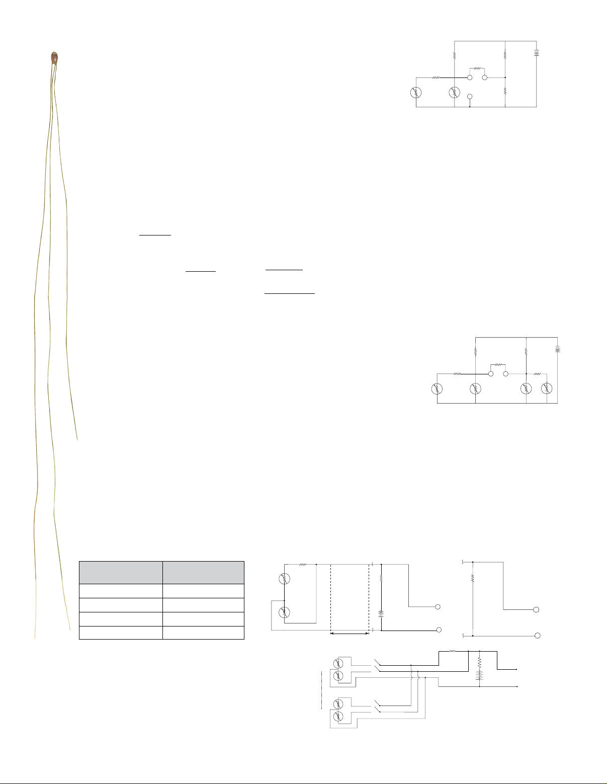
Typical Linear Component Applications
Ein
R1
T2
Figure 2
R1
Ein
R3
R4
Figure 1
RL
Eout
R1
T2
Figure 4
Resistance Mode
R
1
Eout
Example 1:
To measure and record on a 100 mV recorder temperature in the range 30 to 40°C.
1. Select Part number 44202 (temperature range -5°to +45°C)
basic equation E
= (-0.0056846 Ein) T +0.805858 E
out1
in
2. Calculate Ein for 10°C equal to 100 mV
(E
[(-0.0056846 E
) 30°C + 0.805858 Ein] - [(-0.0056846 Ein) 40°C + 0.805858 Ein] = 100 mV
in
, @30°C - E
out
@ 40°C) = 100 mV
out1
0.056846 E
E
= 1.7591 Volts
in
T1
= 100 mV
in
R1
R2
RL
Eout2
Eout1
T2
3. Using the Linear network as two legs of a Wheatstone bridge add the two additional legs,
R
and R4 so that E
3
(1) The voltage drop across R
(2) E
= 1.7591 Volts
in
(3) 1000 ohms ≤ R
If R
(4) E
(5) E
R
+ R4 is more than 5 K, some degradation of linearity will occur.)
3
E
=
R4
out1
E
= E
R4
in R4
+ R
R
3
= -0.0056846 (1.7591 Volts) (+30°C) +0.805858 (1.7591 Volts) = 1.1180 Volts
= E
R
out1
Solve for R3 and R4 1.1180 =
4. Apply E
to the recorder input terminals and the result is a direct reading 10°C full scale thermometer.
out2
= 0 when T = 30°C. (See Figure 1.) R3 and R4 are calculated from five known conditions.
out2
+ R4 ≤ 5000 ohms. (If R3 + R4 is less than 1 K, excessive battery drain may occur.
3
4
Ein R4
=
4
(ER4) should equal Eout1 at 30°C for E
4
1.7591
R
or 1.1180 =
+ R3 R3 + R
3
4
4
1.7591
R
4
R4 + 100-R
and let us choose R
R
R3 = 364.45 ohms
4
to equal zero.
out2
3
= 635.55 ohms
4
+ R4 = 1000 ohms.
Example 2:
To make a 4 digit 100 mV sensitivity digital voltmeter into a direct reading differential
thermometer whose ambient range is -30 to 40°C;
1. Select Part number 44203 (temperature range -30 to 50°C)
R
basic equation Eout = (-0.0067966 Ein) T +0.65107 Ein
2. Calculate Ein so that 10 mV equals one degree C. (This is done so that the Digital
Volt Meter will read directly in temperature with 0.01°C readability)
(E
[(-0.0067966 E
)(-30) +0.65107 Ein] - [(-0.0067966 Ein) (40) + 0.65107 Ein] = 0.700
in
0.47576 E
E
, @ -30°C - E
out
, @ +40°C) = 0.700 Volts
out
= 0.700
in
= 1.4713 Volts
in
2
T1
3. Connect two linear networks (#44203) as shown in Fig. 2.
4. Apply E
to the Digital Volt Meter input terminals for a direct reading differential thermometer.
out
Example 3:
To make a 2-wire system from a 3-wire system using any Linear component:
1. For voltage mode, connect R
to the thermistor composite. (See Figure 3.) This unit can function as the
2
temperature sensor and be located remote from the signal conditioning circuit by up to distance “D”.
2. The resistance mode differs from the voltage mode only by removal of the power source. (See Figure 4.)
3. Acceptable distance “D” varies according to the temperature range. Using #22 wire “D” may be as follows
without loss of accuracy in both 2-wire and 3-wire systems. Where distance “D” is greater than indicated,
heavier gauge wire may be used.
Temperature Distance
Range “D”
R2
T1 R1
A
A
R1
0 to 100°C 30 m (100')
-5 to 45°C 91 m (300')
-30 to 50°C 91 m (300')
30 to 100°C 91 m (300')
Example 4:
Multiplexing to connect any number of thermistor
composites to a single signal conditioning circuit.
(See Figure 5.) Multiplexing can be accomplished
much more easily with a two-wire system, such as
shown in Figure 5.
Lead Colors:
Green: Common to T1 & T2
Brown: T1 Red: T2
T2
D-45
SENSOR1
SENSORN
Ein
B
D
T1
T2
T1
T2
E
out
B
R2
Figure 5
Ein
R2
T1
 Loading...