

Page 1
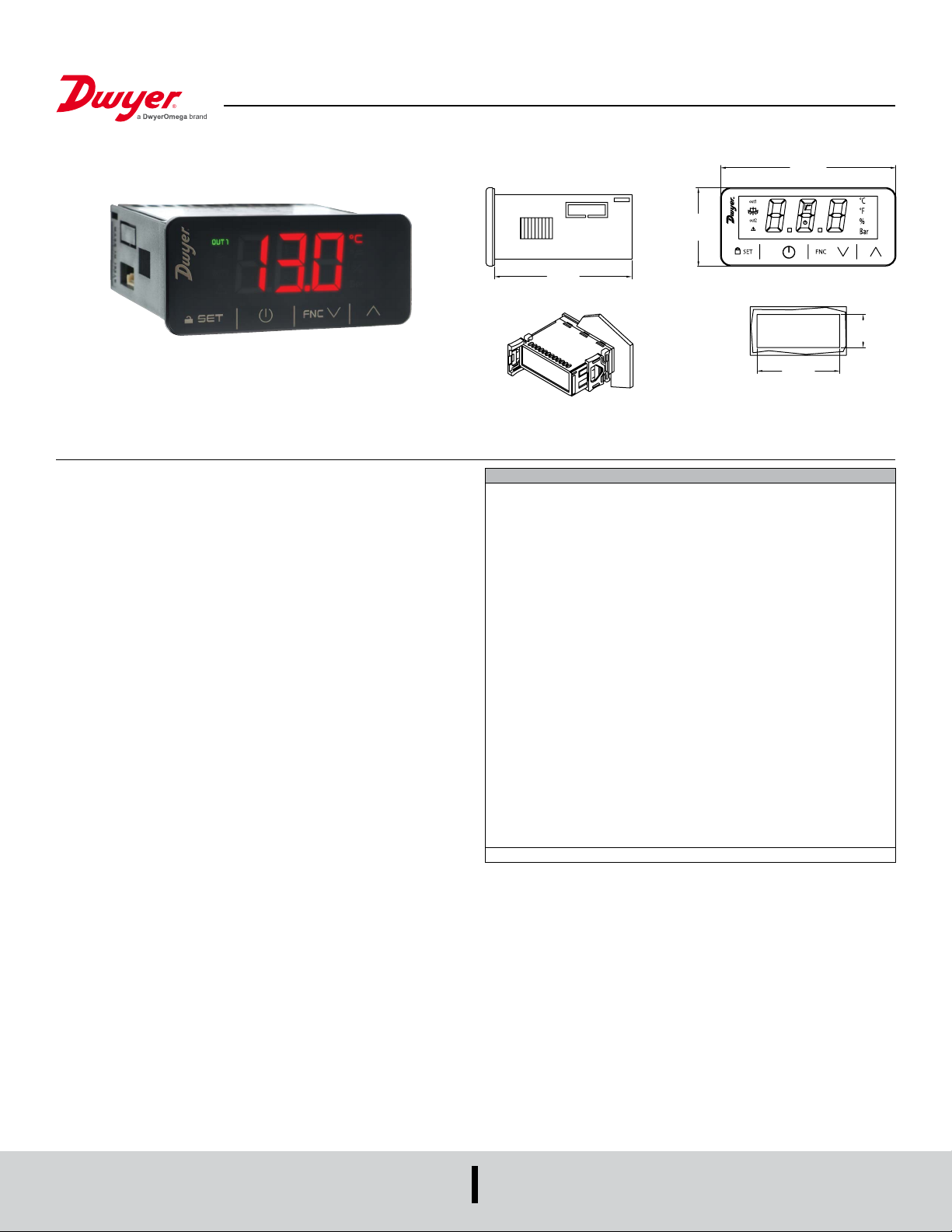
Series 40M2 Digital Temperature Controller
2-15/16
®
Specications - Installation and Operating Instructions
1-5/16
[33]
2-5/16
[59]
Bulletin T-40M2
[75]
DRILLING TEMPLATE
2-13/16
[71.0]
1-1/8
[29.0]
The Series 40M2 Digital Temperature Controller accepts a variety of inputs for
temperature measurements and set points up to 999°F/537°C. Observing the current
status of the controller is made easy with the 3-digit, multi-color LED display that has
alarm and output symbols. For added versatility, the temperature units can be eld
selected for °F or °C. A ashing alarm informs users when the current temperature
exceeds preset limits. The On-Off/PID and PID with auto-tuning provide accurate and
reliable control in complex applications. The Modbus
used to communicate over a TTL/RS-485 interface. When programming multiple units,
the 40X2-K programming key is available to reduce setup time.
INSTALLATION
Note: Unit must be mounted away from vibration, impacts, water and corrosive gases.
• Cut hole in panel 2-51/64 x 1.9/64 in (71 x 29 mm).
• The thickness of the panel must be between 1/32 and 5/64 in (0.8 and 2.0 mm).
• Insert unit into hole from the front side of the panel.
• Slide the mounting bracket securely against the panel from the rear of the unit.
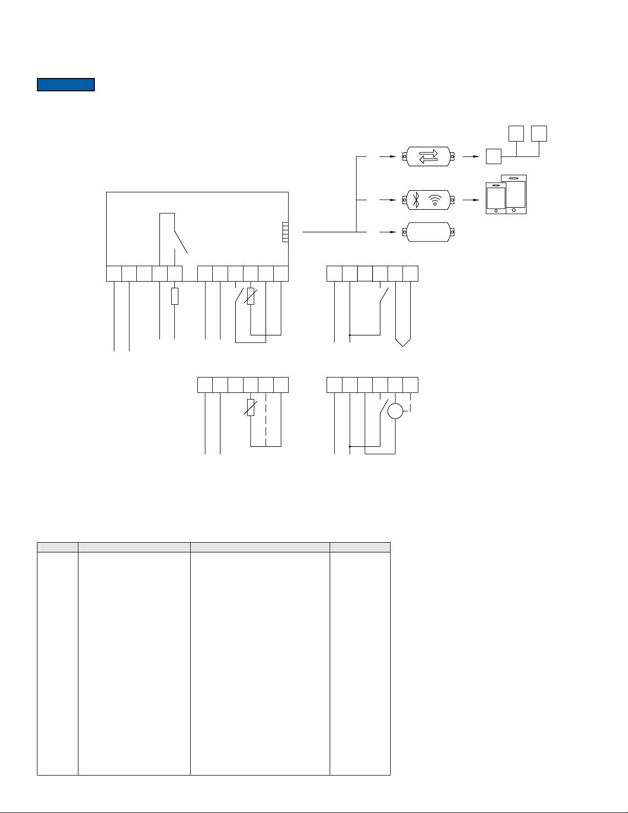
• Wiring diagram is displayed on top of the switch.
®
protocol TTL slave port can be
SPECIFICATIONS
Sensor Input: RTD, thermocouple, thermistor, current, or voltage. 1 digital
multipurpose dry contact.
Multipurpose Input: Dry contact 3.3 V, 1 mA (not available if sensor input is
congured for Pt 100, Pt 1000, or Ni 120 3-wire input).
Sensor Input Types: Current: 0-20 mA/4-20 mA, congurable; Voltage: 0-10
V/2-10 V, congurable; PTC probe: -58 to 302°F (-50 to 150°C); NTC probe: -40
to 230°F (-40 to 110°C); PT100 probe*: -148 to 999°F (-100 to 650°C); PT1000
probe*: -148 to 999°F (-100 to 650°C); Ni120 probe: -112 to 572°F (-80 to 300°C); J
T/C*: -130 to 999°F (-90 to 700°C); K T/C*: -130 to 999°F (-90 to 999°C).
Output: 0-10 VDC or PWM (12-24 VAC/DC model needs to be powered @ 24
VAC/DC for 0-10 VDC or PWM).
Control Type: On-Off/PID, PID with auto-tuning.
Power Requirements: 115-230 VAC or 12-24 VAC/DC depending on model.
Communication: TTL/RS-485 interface, Modbus
BMSF.
Display: 3 digit LED display.
Resolution: 1°F (0.1°C) for thermocouples; 1°F (0.1°C) for all other models.
Relay (K1) Output: 16 A in-rush res. @ 250 VAC, SPST, type 1.
Dry Contact: One multi-purpose, 3.3 V, 1 mA rating.
Alarm: Built in buzzer.
Temperature Limits: Operating: 23 to 131°F (-5 to 55°C).
Humidity Limits: 10-90% RH, non-condensing.
Storage Temperature: -13 to 158°F (-25 to 70°C).
Weight: 2.3 oz (65 g).
Front Panel Rating: IP65.
Compliance: CE, UKCA, cURus.
*Upper range limited by 3-digit display.
®
protocol port for programming or
DWYER INSTRUMENTS, LLC
P.O. BOX 373 • MICHIGAN CITY, INDIANA 46360, U.S.A.
Phone: 219-879-8000
Fax: 219-872-9057
www.dwyer-inst.com
e-mail: [email protected]
Page 2
WIRING
1
12-24 V
Pt 100/Pt 1000/NI 120
BMS
Avoid installing the temperature probe cables in close proximity of any power cables. Maximum cable length of 10 m (32.8 ft) for all cables, except for the PWM analog output
which is 1 m. A temperature offset adjustment may be made using the CA1 parameter. Connection methods include xed and plug-in screw terminal blocks for wires up to 14
AWG (2.5 mm
NOTICE
2
) and pico-blade connector.
To reduce any electromagnetic interference, mount the power cables as far away as possible from the signal cables.
• Disconnect the power supply before carrying out any type of maintenance.
TTL/RS-485
serial interface
or
EVlink BLE or
Wi-Fi module
power supply:
15... 230 VAC in 40M2-20
AC/DC in 40M2-40
K1
(u1 def. = 1)
12 A continuous
(config.)
regulator 1
mains
40M2
AO
gnd id Pb1
7
0-10 V/PWM
reference
9 12111085421
multi-purpose
regulation
TTL MODBUS port
PTC/NTC
Pb1
7 7
9 1211108
AO
7
0-10 V/PWM
AOgndAO
or
or
gnd id Pb1
9 1211108
multi-purpose
reference
gnd 12 V Pb1
9 1211108
programming key
+ regulation
J/K
100
1010
01
smartphone
or tablet
0-10 V/PWM
reference
regulation
0-10 V/PWM
0-20 mA/4-20 mA/0-10 V/2-10 V
reference
multi-purpose
regulation
INITIAL SETUP
1. Install unit with the provided instructions above.
2. Electrically wire the device as described in the wiring section. A power on self test will begin once power is applied. This test will take a few seconds and the display will
switch off when it’s complete.
3. Congure the device as shown in the section SETTING CONFIGURATION PARAMETERS. The recommended parameters for rst time use are listed in the chart below:
Parameter Description Range or Options Factory Setting
SP
P0
P0
P0
P0
P0
P0
P0
P0
P0
P0
P0
P0
P0
P0
P2
P2
r5
r5
r10
r10
uA
uA
uA
uA
ub
ub
Set point
Type of input probe
Type of input probe
Type of input probe
Type of input probe
Type of input probe
Type of input probe
Type of input probe
Type of input probe
Type of input probe
Type of input probe
Type of input probe
Type of input probe
Type of input probe
Type of input probe
Display units
Display units
Cooling or heating for set point 1
Cooling or heating for set point 1
Cooling or heating for set point 2
Cooling or heating for set point 2
Analog output
Analog output
Analog output
Analog output
Analog output type
Analog output type
r1 to r2
0 = PTC
1 = NTC
2 = J Type Thermocouple
3 = K Type Thermocouple
4 = 3 wires Pt 100
5 = 2 wires Pt 100
6 = 3 wires Pt 1000
7 = 2 wires Pt 1000
8 = 4-20 mA
9 = 0-20 mA
10 = 2-10 V
11 = 0-10 V
12 = 3 wires Ni 120
13 = 2 wires Ni 120
0 = °C
1 = °F
0 = Cooling
1 = Heating
0 = Cooling
1 = Heating
0 = disabled
1 = proportional to regulation temperature
2 = regulator 1
3 = regulator 2
0 = 0-10 V
1 = PWM
0
2
2
2
2
2
2
2
2
2
2
2
2
2
2
0
0
0
0
0
0
1
1
1
1
0
0
Page 3
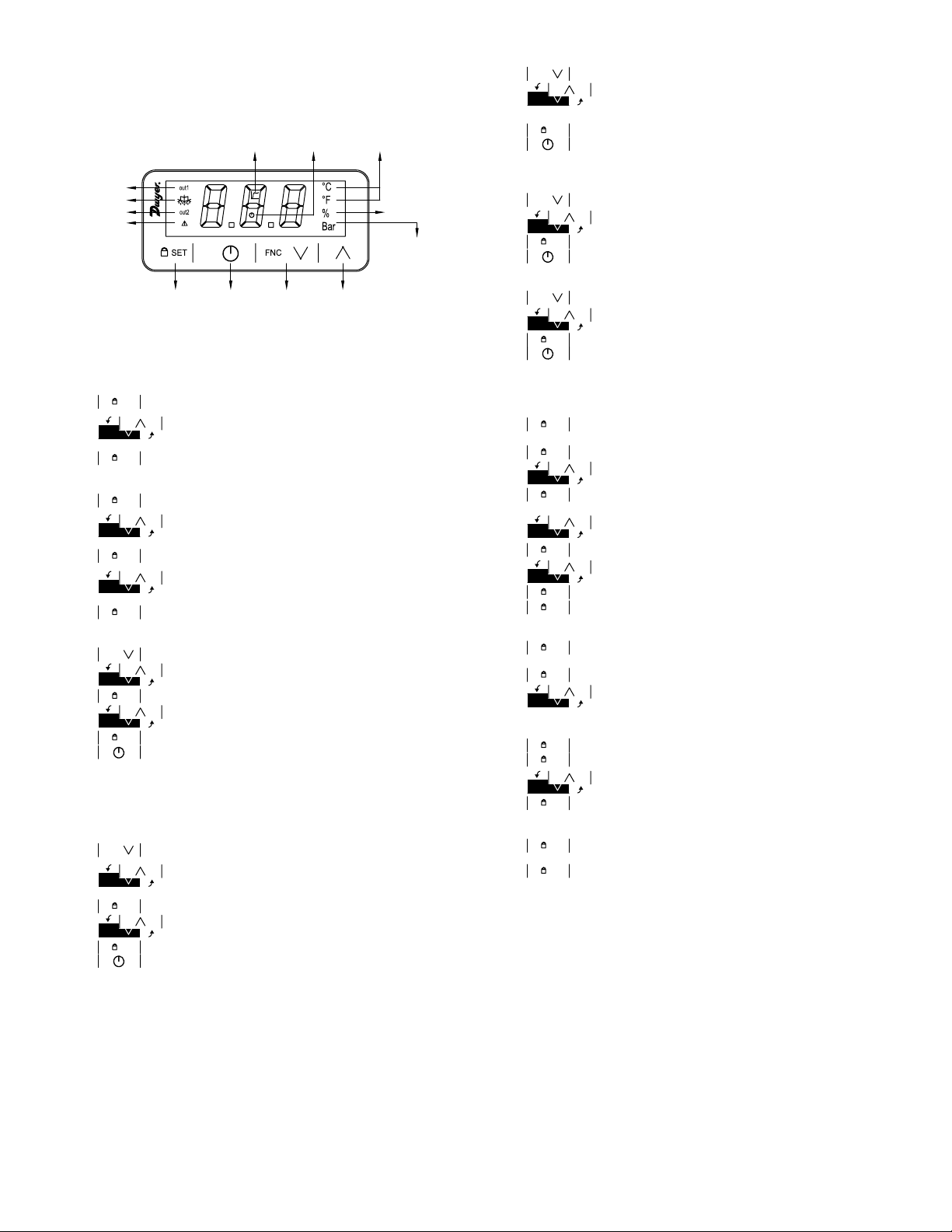
USER INTERFACE AND MAIN FUNCTIONS
REGULA
REGULA
OF MEASUREMENT
TEMPERATURE
LOCK
FUNCTIONS
A. Switching the Device On and Off
Press the POWER key for 4 seconds. When the display is switched on, the
display will show the P5 value.
ANALOG
OUTPUT ON/STAND-BY
UNIT OF
MEASUREMENT
B. Displaying the number of start-ups of the relay.
1.
2.
FNC
Press the down key for four seconds.
FNC
Press the UP or DOWN key within 15 seconds to select a
label. nS1 = display the number of start-ups of the K1 relay in
thousand.
SET
3.
4.
Press the SET key.
Press the ON/STANDBY key ( or take no action for 60 seconds)
to exit the procedure.
TOR 1
RESERVED
ALARM
TOR 2
PERCENTAGE
PRESSURE UNIT
SET,
KEYPAD
ON/STAND-BY
ESCAPE
DOWN,
ADDITIONAL
UP
B. Unlocking the Keypad
Touch any key for one second, until the display shows “UnL”.
C. Setting the Set Point (If u0=0,3 or 4)
1. Ensure the keypad is not locked.
2.
3.
4.
SET
Press the SET key. The display should show the label “SP”.
Press the UP or DOWN key within 15 seconds to set the value
FNC
SET
within the limits r1 and r2. The default on the unit will be 0 to
350.
Press the SET key or take no action for 15 seconds to set the
set point.
D. Setting Set Point 1 and Set Point 2 (if u0=1 or 2)
SET
1.
2.
3.
4.
5.
Press the SET key. The display should show the label “SP”.
Press the UP or DOWN key within 15 seconds to set the value
FNC
SET
within the limits r1 and r2. The default on the unit will be 0 to
350.
Press the SET key. The display will show the label “SP2”.
Press the UP or DOWN key within 15 seconds to set the value
FNC
SET
of set point 2 within the limits r7 and r8. The default on the unit
will be 0 to 350.
Press the SET key or take no action for 15 seconds to set the
set point.
E. PID Control Activation with Auto-tuning (if r20=1, default)
FNC
1.
2.
3.
4.
5.
6.
Press the DOWN key for 4 seconds.
FNC
FNC
Press the UP or DOWN key within 15 seconds to select the
SET
label “tun”.
Press the SET key.
Press the UP or DOWN key within 15 seconds to set “1”.
SET
Press the SET key.
Press the ON/STAND-BY key (or take no action for 60
seconds) to exit.
F. Silencing the Buzzer (if A13 = 1)
1. Touch any key. If u1, u2, or u3 = 3, the alarm output is deactivated.
ADDITIONAL FUNCTIONS
A. Displaying/setting the value delivered by the analog output.
1.
2.
a) uA – displaying the value from the analog output
FNC
Press the DOWN key for 4 seconds.
Press the UP or DOWN key within 15 seconds to select a label.
FNC
b) uM – modifying the value from the analog output
SET
3.
4.
5.
6.
Press the SET key.
FNC
Press the UP or DOWN key to select uM and set the value.
SET
Press the SET key.
Press the ON key or take no action for 60 seconds to exit the
procedure.
C. Displaying the temperature detected by the compressor probe.
1.
2. Press the UP or DOWN key within 15 seconds to select a label.
3.
4.
FNC
Press the DOWN key for four seconds.
FNC
SET
Pb1 = regulation temperature.
Press the SET key.
Press the ON/STANDBY key ( or take no action for 60 seconds)
to exit the procedure.
D. Displaying the temperature detected by the regulation probe.
1.
2.
3.
4.
FNC
Press the DOWN key for four seconds.
FNC
Press the UP or DOWN key within 15 seconds to select a label.
SET
Touch the SET key.
Press the ON key or take no action for 60 seconds to exit the
procedure.
SETTINGS
A. Setting Conguration Parameters
SET
1.
Press the SET key for four seconds. The display will then show
the label “PA”.
SET
2.
3.
4.
Press the SET key.
FNC
Press the UP or DOWN key within 15 seconds to set the PAS
value. *Default is “-19”).
SET
Press the SET key or take no action for 15 seconds and the
screen will show the label “SP”.
5.
6.
7.
8.
9.
FNC
FNC
Press the UP or DOWN key to select a parameter.
SET
Press the SET key.
Press the UP or DOWN key within 15 seconds to set the value.
SET
Press the SET key or take no action for 15 seconds.
SET
Hold the SET key for 4 seconds or take no action for 60
seconds to exit the procedure.
B. Restoring to Default Factory Settings and Saving Customized Settings
1.
2.
3.
a) Value: 149 – value for restoring the factory information
SET
Hold the SET key for 4 seconds. The display will show the label
SET
FNC
“PA”.
Press the SET key.
Press the UP or DOWN key within 15 seconds to set the value.
(default)
b) Value: 161 – value for saving customized settings
4.
5.
6.
7.
SET
Press the SET key or take no action for 15 seconds.
SET
Press the SET key.
FNC
Press the UP or DOWN key within 15 seconds to set “1”.
SET
Press the SET key or take no action for 15 seconds. The
display will show “- - -” ashing for 4 seconds and then it will
exit the procedure.
8.
9. Disconnect the device from the power supply.
10.
SET
SET
Hold the SET key for 2 seconds before action 6 if to exit the
procedure.
Page 4
TEMPERATURE
TEMPERATURE
TEMPERATURE
TURE
R17 R17 R17 R17
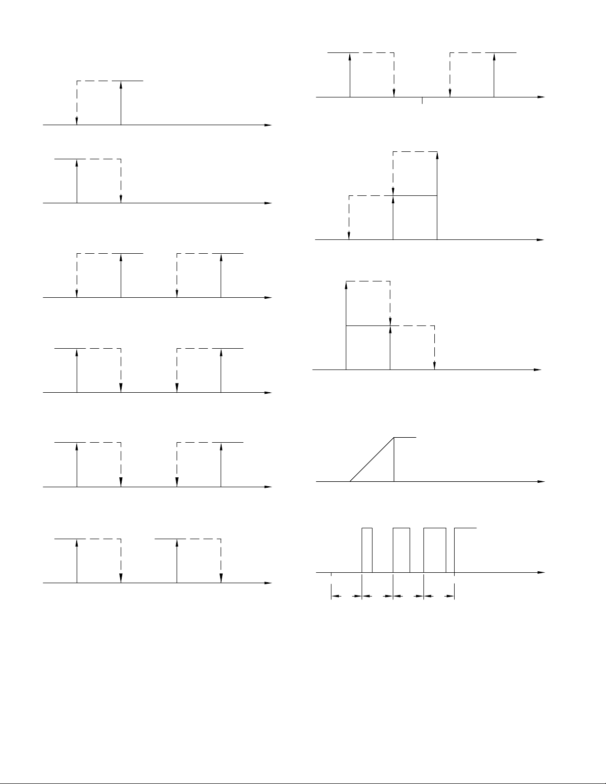
FUNCTIONAL MODES
COLD MODE REGULATION [R5 = 0].
TEMPERATURE
HOT MODE REGULATION [R5 = 1].
TEMPERATURE
TEMPERATURE
TEMPERATURE
TEMPERATURE
TEMPERATURE
TEMPERATURE
A. On-Off Operating Logic
1. One regulator
REGULATOR
OFF
SP SP+RO
ON
REGULATION
B. Neutral zone regulation (u0 = 3)
ON
REGULATOR 2
OFF
SP-(R13/2)-R0
C. Two step regulation (u0 = 4)
Cold mode (r5 = 0)
SP-(R13/2) SP+(R13/2) SP+(R13/2)+R0
ON
REGULATOR 1
OFF
SP
REGULATION
ON
REGULATOR
OFF
SPSP-RO
2. Two regulators with two independent set points Cold mode regulation set point
1 (r5 = 0) and cold mode regulation set point 2 (r10 = 0).
ON
REGULATOR 1
OFF
SP SP+RO SP2 SP2+R6
Cold mode regulation set point 1 (r5 = 0) and hot mode regulation set point 2
(r10 = 1).
ON
REGULATOR 2
OFF
SP2SP-R6 SP SP+R0
Hot mode regulation set point 1 (r5 = 1) and cold mode regulation set point 2
(r10 = 0).
ON
REGULATOR 1
OFF
SPSP-R0 SP2 SP2+R6
REGULATOR 2
OFF
REGULATOR 1
OFF
REGULATOR 2
OFF
REGULATION
ON
REGULATION
ON
REGULATION
ON
REGULATION
ON
REGULATOR 2
OFF
ON
REGULATOR 1
OFF
SP
Hot mode (r5 = 1)
ON
D. Operation with analog output proportional to regulation temperature
Note: ua = 1, default
Analog output 0-10 V (ub = 0, default)
0V
UC
SP+[R13/2] SP+R13
REGULATOR 2
ON
SP-[R13/2]SP-R13
OFF
REGULATOR 1
10V
UD
REGULATION
OFF
SP
REGULATION
REGULATION
Hot mode regulation set point 1 (r5 = 1) and hot mode regulation set point 2 (r10
= 1).
ON
REGULATOR 1
ON
REGULATOR 2
OFF
SPSP-R0 SP2SP2-R6
OFF
REGULATION
Analog output PWM (ub = 1)
0V
UC
UD
10V
REGULATION
TEMPERA
Page 5

Parameter Description Units Range or Options Factory Setting
SP
SP2
CA1
P0
Set point
Set point 2
Probe adjustment
Type of input probe
Degrees
Degrees
Degrees
Option
r1 to r2
r7 to r8 (not avail if u0=0,3 or 4)
-25 to 25 C/F
0-PTC, 1-NTC, 2-J Type, 3-K Type, 4-3 wires Pt 100, 5-2
wires Pt 100, 6-3 wires Pt 1000, 7-2 wires Pt 1000, 8-4 to 20
0.0
0.0
0.0
2
mA, 9- 0 to 20 mA,10-2 to 10 V, 11-0 to 10 V, 12-3 wires Ni
P1
P2
P3
P4
P5
P8
u0
u1
uA
ub
uc
ud
rA
r0
r1
r2
r5
r6
r7
r8
r9
r10
r11
r12
r13
r14
r15
r16
r17
r18
r19
r20
r21
C1
C2
C3
C4
C5
C6
C7
C8
A1
A2
A3
A4
A5
A6
A7
A8
A9
A11
A13
i5
i6
i7
POF
PAS
PA1
PA2
bLE
rE0
LA
Lb
Decimal point enable
Engineering units
Minimum process input value
Maximum process input value
Value displayed during normal operation
Display refresh time
Operating logic
K1 output conguration
Analog output conguration
Type of analog output
Regulation temperature for minimum analog output value
Regulation temperature for maximum analog output value
PID control conguration
Set point differential
Minimum set point value
Maximum set point value
Cooling or heating
Differential for set point 2
SP2 minimum value
SP2 maximum value
Lock SP2 for adjustments
Regulator 2 heating or cooling operation
Digital input for SP
Digital input for SP2
Neutral zone value
Proportional band
Integral action time
Derivative action time
Cycle time on for PID regulator PWM relay or analog output
Minimum time on for PID regulator PWM relay or analog output
Minimum time off for PID regulator PWM relay or analog output
Enable auto-tuning
Maximum duration for auto-tuning
Minimum time between two power ons for regulator 1
Minimum time off and delay from power up of regulator 1
Minimum time on regulator 1
Behaviour of regulator 1 during probe alarm
Minimum time between two power ons of regulator 2
Minimum time off and delay from power up of regulator 2
Minimum time on regulator 2
Behaviour of regulator 2 during probe alarm
Temperature alarm 1 set point
Temperature alarm 1 type
Temperature alarm 1 delay
Temperature alarm 2 set point
Temperature alarm 2 type
Temperature alarm 2 delay
Temperature alarm delay upon set point modication & power on
Temperature alarm delay after silencing and persistent alarm
condition
Enable alarm output logic
Temperature alarm switch off from set point
Enable alarm buzzer
Multi-purpose input function
Multi-purpose input activation
Multi-purpose input alarm delay
Enable “ON/Standby” button
Set password
Set rst level password
Set second level password
Enable Bluetooth
Data logger sampling interval
®
protocol address
Modbus
®
protocol baud rate
Modbus
Option
Option
Counts
Counts
Option
Tenths of a
second
Option
Option
Option
Option
Degrees or
Points
Degrees or
Points
Option
Degrees
Degrees
Degrees
Option
Degrees
Degrees
Degrees
Option
Option
Degrees
Degrees
Degrees
Degrees
Seconds
Seconds
Seconds
Seconds
Seconds
Option
Minutes
Minutes
Minutes
Seconds
Option
Minutes
Minutes
Seconds
Option
Degrees
Option
Minutes
Degrees
Option
Minutes
Minutes
Minutes
n/a
Degrees
Option
Option
Seconds
Option
Number
Number
Number
Option
Minutes
Number
Option
120, 13-2 wires Ni 120
0-disable,1-enable if P0=2 or 3, not effective if P0=8,9,10 or
11, position of decimal point 0-n/a, 1 tens digit
0-C, 1-F, 2-%, 3-bar, 4-blank, options 2, 3 and 4 effective only
on LEDS and if P0=8,9,10 or 11
-199 to 999
-198 to 999
0-probe temp, 1-set point (SP)
0 to 250
0 - 1 regulator, 2 - 2 regulators with SP2 relative to SP, 3 - 2
regulators with independent SP & SP2, 3 - neutral zone
regulation, 4 - 2-step regulation
0 - disabled, 1 - regulator 1, 2 - regulator 2, 3 - alarm
0 - disabled, 1 - proportional to probe temperature, 2 regulator 1, 3 - regulator 2
0 - 0-10VDC, 1 - PWM
-199 to ud C/F/points
uc to 199 C/F/points
0 - disabled, 1 - regulator 1, 2 - regulator 2, effective only
u0=1 or 2
1 to 99.9 C/F, if u0= 3 then cold mode regulation differential
-199.0 C/F to r2
r1 to 999 C/F
0-cooling, 1-heating
1 to 99 if u0=3 then heating mode regulation differential
-199 C/F to r8
r7 to 999 C/F
0 - no, 1 - yes
0 - cooling, 1 - heating
-199 to 999 C/F (set point) + r11
-199 to 999 (set point 2) + r12
1 to 999 C/F If u0 = 4 then two steps
1 to 999 C/F
0 to 999
0 to 999
1 to 999
0 to 240
0 to 240
0 - disable, 1 - enable
2 to 240
0 to 240
0 to 240
0 to 240
0 - off, 1 - on
0 to 240
0 to 240
0 to 240
0 - off, 1 - on
-199 to 999 C/F
0 - disabled, 1 - abs min, 2 - abs max, 3 - min relative to SP,
4 - max relative to SP
0 to 999
-199 to 199 C/F
0 - disabled, 1 - abs min, 2 - abs max, 3 - min relative to SP2,
4 - max relative to SP2
0 to 999
0 to 999
0 to 999
0- with alarm active, 1-with alarm not active
1 to 99
0-disable, 1-enable
0-disable, 1-alarm iA, 2-alarm iA+both regulators off, 3-alarm
iA1 & regulator 1 off, 4-alarm iA2 & regulator 2 off, 5-switches
device on/off, 4-modies SP & SP2
0-contact closed, 1-contact open
0 to 999
0-disable, 1-enable
-99 to 999
-99 to 999
-99 to 999
0-disable, 1-enable
0 to 240
1 to 247
0-2,400 baud, 1-4800 baud, 2-9600 baud, 3-19,200 baud
even
0
0
0.0
100
0
5
0
1
1
0
0.0
100
0
2.0
0.0
350.0
0
2.0
0.0
350
0
0
0.0
0.0
5.0
50
60
30
180
0
0
1
240
0
0
0
0
0
0
0
0
0.0
0
0
0.0
0
0
0
0
0
2.0
1
0
0
0
1
-19
426
824
1
15
247
3
Page 6
ALARMS
Code Description Reset How to Correct
Pr1
Compressor probe alarm
AL1
Temperature 1 alarm
AL2
Temperature 2 alarm
iA
Multi-purpose input alarm
iA1
Regulator 1 protection alarm
iA2
Regulator 2 protection alarm
tu0
Auto-tuning alarm failed
tu1
Auto-tuning timeout alarm
Automatic
Automatic
Automatic
Automatic
Automatic
Automatic
Manual
Manual
Check P0
Check integrity of the probe
Check electrical connection
Check A1, A2 and A3
Check A4, A5 and A6
Check i5 and i6
Check i5 and i6
Check i5 and i6
Touch any key
Touch any key, check r21
MAINTENANCE/REPAIR
Upon nal installation of the Series 40M2, no routine maintenance is required. The
Series 40M2 is not eld serviceable and is not possible to repair the unit. Field repair
should not be attempted and may void warranty.
This symbol indicates waste electrical products should not be disposed
of with household waste. Please recycle where facilities exist. Check with
your Local Authority or retailer for recycling advice.
WARRANTY/RETURN
Refer to “Terms and Conditions of Sale” in our catalog and on our website. Contact
[email protected] to receive a Return Materials Authorization number before
shipping the product back for repair. Be sure to include a brief description of the
problem, PO#/Order#/or Invoice# that this unit was purchased on plus any additional
application notes.
Page 7

NOTES
__________________________________________________________________________________________________________________________________________
__________________________________________________________________________________________________________________________________________
__________________________________________________________________________________________________________________________________________
__________________________________________________________________________________________________________________________________________
__________________________________________________________________________________________________________________________________________
__________________________________________________________________________________________________________________________________________
__________________________________________________________________________________________________________________________________________
__________________________________________________________________________________________________________________________________________
__________________________________________________________________________________________________________________________________________
__________________________________________________________________________________________________________________________________________
__________________________________________________________________________________________________________________________________________
__________________________________________________________________________________________________________________________________________
__________________________________________________________________________________________________________________________________________
__________________________________________________________________________________________________________________________________________
__________________________________________________________________________________________________________________________________________
__________________________________________________________________________________________________________________________________________
__________________________________________________________________________________________________________________________________________
__________________________________________________________________________________________________________________________________________
__________________________________________________________________________________________________________________________________________
__________________________________________________________________________________________________________________________________________
__________________________________________________________________________________________________________________________________________
__________________________________________________________________________________________________________________________________________
__________________________________________________________________________________________________________________________________________
__________________________________________________________________________________________________________________________________________
__________________________________________________________________________________________________________________________________________
Page 8

NOTES
__________________________________________________________________________________________________________________________________________
__________________________________________________________________________________________________________________________________________
__________________________________________________________________________________________________________________________________________
__________________________________________________________________________________________________________________________________________
__________________________________________________________________________________________________________________________________________
__________________________________________________________________________________________________________________________________________
__________________________________________________________________________________________________________________________________________
__________________________________________________________________________________________________________________________________________
__________________________________________________________________________________________________________________________________________
__________________________________________________________________________________________________________________________________________
__________________________________________________________________________________________________________________________________________
__________________________________________________________________________________________________________________________________________
__________________________________________________________________________________________________________________________________________
__________________________________________________________________________________________________________________________________________
__________________________________________________________________________________________________________________________________________
__________________________________________________________________________________________________________________________________________
__________________________________________________________________________________________________________________________________________
__________________________________________________________________________________________________________________________________________
__________________________________________________________________________________________________________________________________________
__________________________________________________________________________________________________________________________________________
__________________________________________________________________________________________________________________________________________
__________________________________________________________________________________________________________________________________________
__________________________________________________________________________________________________________________________________________
__________________________________________________________________________________________________________________________________________
__________________________________________________________________________________________________________________________________________
Modbus® is a registered trademark of Schneider Electric USA, Inc.
Printed in U.S.A. 12/23 FR# 444661-00 Rev. 2©Copyright 2023 Dwyer Instruments, LLC
DWYER INSTRUMENTS, LLC
P.O. BOX 373 • MICHIGAN CITY, INDIANA 46360, U.S.A.
Phone: 219-879-8000
Fax: 219-872-9057
www.dwyer-inst.com
e-mail: [email protected]
 Loading...