

Page 1

TABLE OF CONTENTS
Model: 400B-CV and 402B-CV
M3778/0602
SECTION 1
1.1 GENERAL DESCRIPTION
1.2 OPTIONS
SECTION 2 SPECIFICATIONS
SECTION 3 INSTALLATION
3.1 UNPACKING/ REPACKING
3.2 CONFIGURING
3.3 MOUNTING
3.4 WIRING
SECTION 4 CALIBRATION AND SCALING
Note: This manual is for the enhanced version of the Model 400
and 402 units. For models 400 and 402 before 3-2002 with serial
numbers without the letter “N” please refer to manual part
number M0035.
Page 2

SECTION 1 DESCRIPTION
1.1 DESCRIPTION.
This manual contains installation, operation, and calibration
information for Series 400 digital process indicators. These
solid-state instruments are designed for accurate, reliable, and
trouble-free display of voltage or milliamps. All instruments
feature a dual-slope A/D converter digital linearization, and a
large 0.8” (20mm) easy-to-read 4-digit LED display. Input
voltage or current can be scaled to Engineering units from
–999 to +9999 counts.
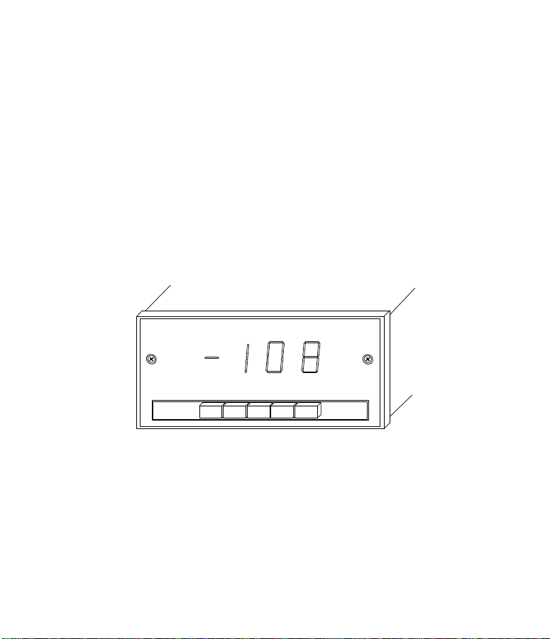
The displays are in-line, uniplanar, 7-segment red
LEDS, easy to read through the front Plexiglas panel. A -OL
displayed on the read-out indicates a negative polarity
overload. Positive readings are inferred (no sign displayed).
OL indicate a positive overload condition. All units operate
from 100, 120, 220, or 240VAC 50-60 Hz power source. A
power connector and ground screw for shield are located at
the rear of the instrument. The instrument case is made of
solid die-cast aluminum, which is rugged enough to withstand
the most hostile environments. It is designed to mount in a
panel. The optional rack mounts can accommodate up to 3
units. Bench mount option 400-W5 provides for convenient
bench top use.
1
Page 3
Multiple Input Options,
Models 402 and 405
Model 402 can accept five inputs of the same input either
voltage or current. Buttons numbered 1-5 are located below
display. Individual input is selected by pressing appropriate
button.
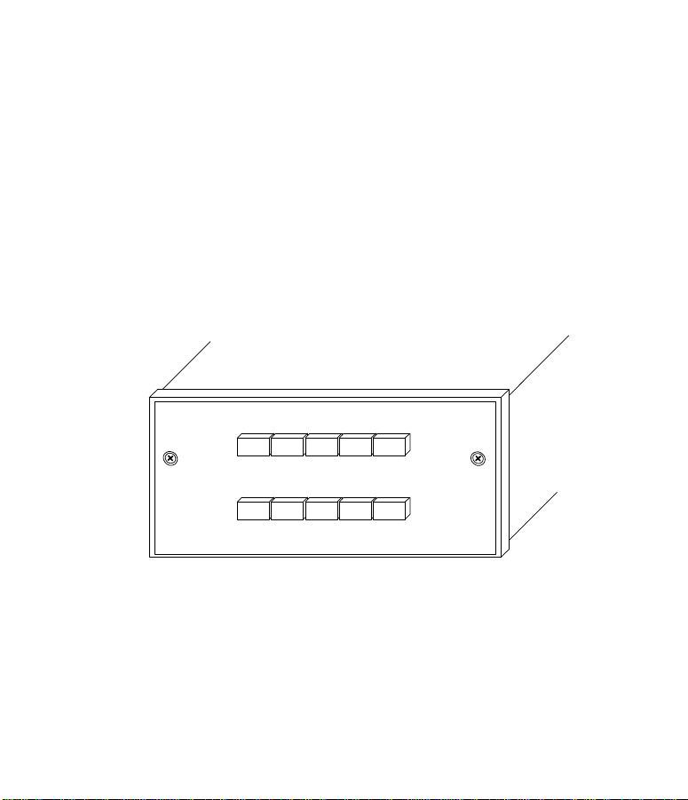
The Model 405A provide 10-switchable inputs to a single
indicator. Model 405A are housed in the same rugged case
design as the basic indicator. Each may be rack-mounted
beside another 405A or indicator. Pushbuttons are in two rows
of five and are numbered 1-10, 11-20, etc. Each row is
interlocked to prevent simultaneous input selection.
1 3 4 52
Model 402
2
Page 4
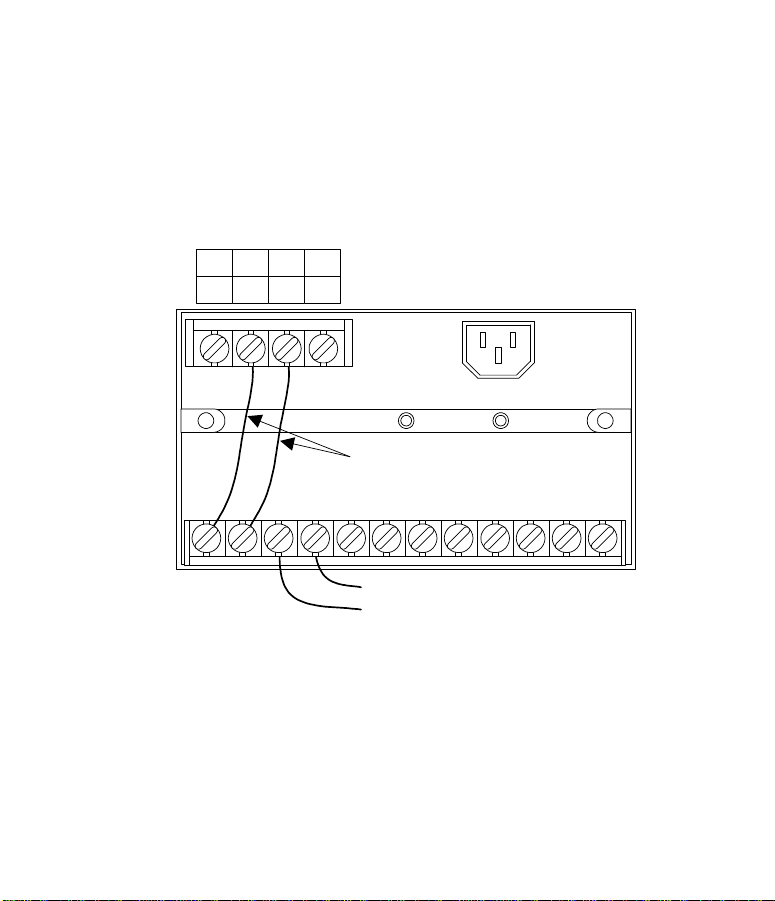
Figure 2. Input Sensor Connections 402A
+V -V
-I +I
-
+
3
+
-
VOLTAGE
CURRENT
Copper Wire
-
+
SENSOR WIRES 402 5 PL
+
12345
-
+
-
+
-
Page 5
USING THE EXTERNAL SWITCHING UINTS (MODELS 405
The External Switching Units provide 10 switchable inputs to a
single indicator. Inputs are selected by two rows of front panel
pushbuttons labeled 1-10. (For special numbering contact
factory). Pressing a particular pushbutton selects that input
point for display. Each row of pushbuttons is interlocked so
that only one pushbutton within that row is selected at once
time.
1 3 4 52
6 8 9 107
Model 405
4
Page 6

SECTION 2 SPECIFICATIONS
Input Range:
mA: 0-20mADC
Voltage: 0-10 VDC
Sensitivity:
Maximum: 200uV/count; 0.4uA/count
Minimum: 1 count
Input Impedance:
MA: 5Ω
Voltage: > 1MΩ
A/D Read Rate:
2 per second nominal
Power:
115VAC ± 10%, 50-60 Hz
230VAC ± 10%, 50-60 Hz
30mA Max input current @ 115VAC
Operating Ranges:
Temperature: 0 to 50°C
Relative Humidity: 10-80% RH non-condensing
5
Page 7

Storage Range:
-40 to 65°C
Size:
Case: 144mm W x 72mm H x 173 mm D
(5.768” x 2.84” x 6.82”)
Maximum Weight:
1.7 kg / 2.5 lb
Panel cutout:
68mm H x 138mm W
2.68” H x 5.44” W
PERFORMANCE SPECIFICATIONS
Reference Operating Conditions (ROC):
±10% line voltage
23 ±2 °C ambient temperature
<80% RH non- condensing
Accuracy (at ROC):
0.02% RDG +/- 1 count
6
Page 8

Noise Rejection:
NMRR: ≥ 60 db @ 50/60 Hz, ± 0.1Hz
CMRR: ≥ 120 db@ 50/60 Hz, ± 0.1Hz with 250Ω unbalance.
Overload Protection:
Power Lead to ground: 1500VDC or AC RMS
Voltage: Up to 250VDC or VAC for I minute, V+ to V-
mA: Up to 150mADC mAAC for 1 minute, +I to -I
Stability With Temperature:
Zero: 1µV/°C
Span: 0.01% rdg /°C
Stability With Time:
10 counts/year max
Repeatability:
±1 count
7
Page 9

SECTION 3 INSTALLATION
3.1 UNPACKING / REPACKING
The Series 400 indicators are rugged, but they must be
properly packed. Instruments are shipped in a customdesigned carton for shipping, but damage may occur. When
you receive your instrument, look for evidence of transit
damage. If damage is found, ask the carrier to prepare a
Damage Inspection Report and notify our Instrument Repair
Department immediately. If your instrument has arrived in
good condition, you may perform the functional test described
in 3.2.2 to verify proper operation.
REPACKING AND RETURNING THE INSTRUMENT
The original shipping container should be retained in case the
instrument must be returned for repair or modification. When
returning an instrument for any reason, advise us of the model
number, serial number, your name, billing address, shipping
address, phone number and a description of the problem.
This information will enable our Instrument Repair Department
to expedite the return of your instrument. Instruments being
returned to the factory are required to be shipped freight
prepaid.
Instruments being returned for warranty service must
also refer to the original purchase date on packing lists and
8
Page 10

purchase orders. Instruments without this information will be
processed as a non-warranty repair at current service rates.
If the original shipping container has been discarded,
pack your instrument for shipping as follows:
Select a strong cardboard box of sufficient size to allow an
inch of packing material around all sides of the unit.
a. Ensure that the printed circuit boards are secured
and front and rear panels are firmly in place.
b. Wrap the instrument in plastic or strong paper.
Place it centrally in the shipping container, and
pack poly foam, bubble pack, or rubberized hair
around all six sides of the instrument.
c. Tape the carton flaps securely and label the
container “FRAGILE, DELICATE INSTRUMENT”.
Ship the instrument, freight prepaid (do not ship by
U.S mail)
9
Page 11

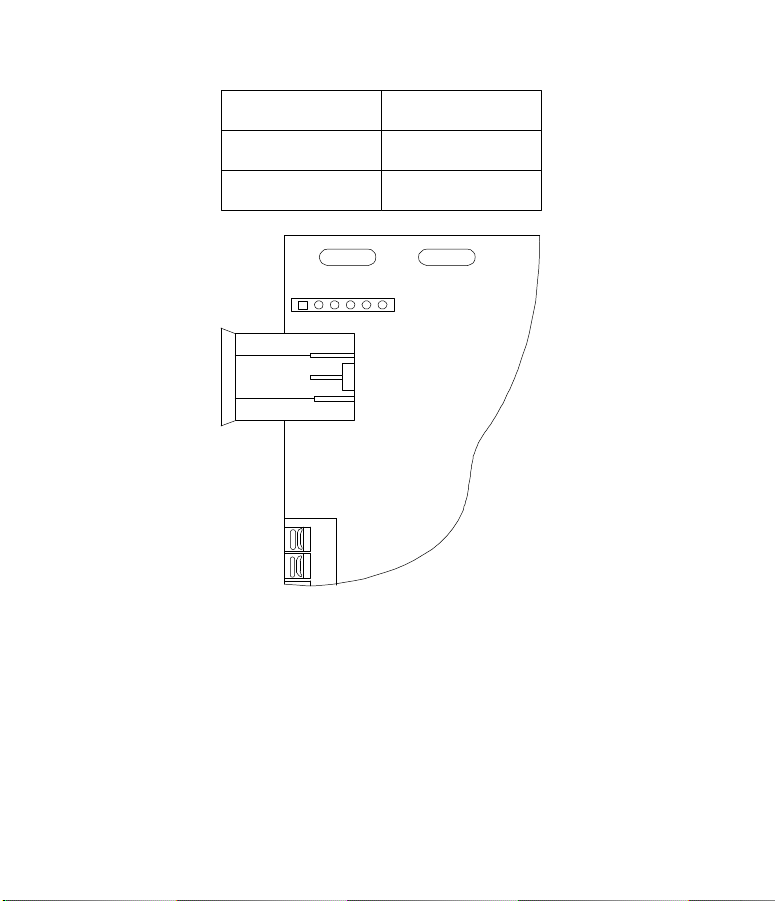
Input Voltage Selection (requires removal)
Input voltage 115 or 220VAC, is selectable by cutting and
adding jumpers on the main board as shown on the next page.
Locate JP18 on the printed circuit board. Cut and make
connection as shown on table depending on input voltage.
REMOVING THE ELECTRONICS FROM THE ENCLOSURE
1- Make sure to disconnect power from the unit
2- Remove the three back cover screws and remove
the rear panel
3- Remove the screw located directly above the AC
plug
4- Remove two screws from the front panel lens and
remove lens
5- Remove two screws from the front holding the
Board assembly and pull it out of the case.
6- Reinstall the assembly when finished.
10
Page 12
Input Voltage JP18
120 VAC
220 VAC
1 2 3 4 5 6
1-2, 4-5
2-3, 5-6
JP18
11
Page 13
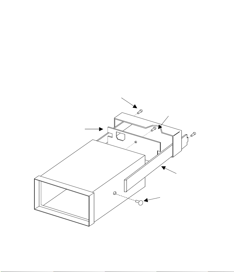
3.3 INSTALLATION
Panel Mounting
Panel mounting hardware is supplied standard with the
instrument. The instrument bezel butts against the front of the
mounting panel; the mounting bracket fits over the instrument
rear panel. The bracket screws force it against the rear of the
mounting panel, locking the instrument in place. Panel cutout
dimensions are 68mm x 138mm (2.68” x 5.44”).
BRACKET
SCREW 2 PL
REAR COVER
SCREW
REAR PANEL
PANEL
MOUNTING
BRACKET
PLASTIC PLUG
12
Page 14
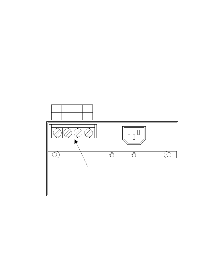
3.4 WIRING THE INSTRUMENT.
All signal input connections are made to the instrument
using screw terminals. To gain access to the recessed
terminal strip, the rear cover panel must be removed. The four
signal input terminals are located in the upper-left corner, and
are labeled +I, +V, -V, and -I.
REMOVE THE POWER CORD BEFORE WIRING
Basic Single Channel Wiring
+V -V
-I +I
VOLTAGE
CURRENT
SENSOR INPUT TERMINALS
13
Page 15
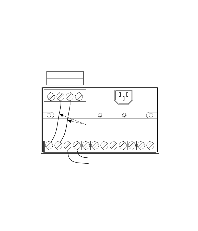
Model 402 Switching Unit Wiring
+V -V
-I +I
-
+
14
+
-
VOLTAGE
CURRENT
Copper Wire
-
+
SENSOR WIRES 402 5 PL
+
12345
-
+
-
+
-
Page 16

SECTION 4
CALIBRATION AND SCALING
4.1 APPLYING POWER TO THE INSTRUMENT
Power is applied to the instrument as long as the
instrument is plugged into an active source. To remove power,
unplug the power cord from the instrument or AC outlet.
To eliminate shock hazard or possible instrument
damage, always remove the power cord either from the
instrument or power source before configuring the indicator.
4.2 Selecting mA or Volts Input Mode
To select between mA or Volts input mode, remove the front
panel lens to gain access to the display board. Behind the
display is a DIP switch used to set the indicator’s input
measuring mode. See the drawing on the following page
showing DIP switch location as well as the location of the SET
and ENTER scaling buttons.
15
Page 17
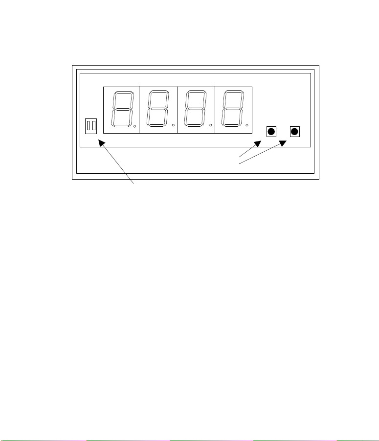
PROCESS/SCALING
16
SET ENTER
SCALING
BUTTONS
Page 18
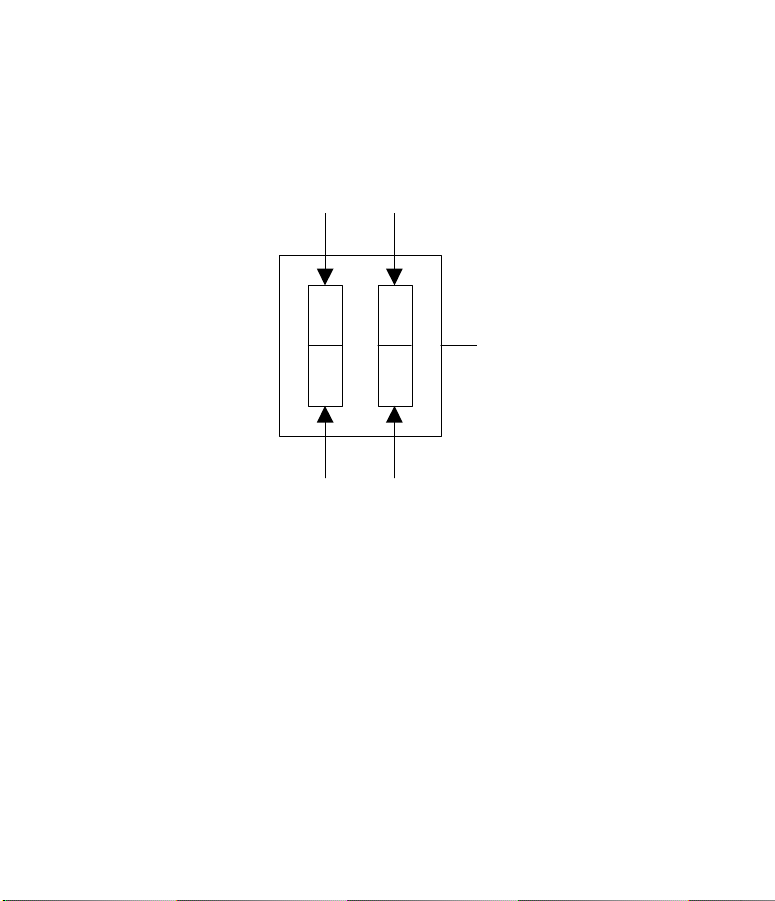
PUSH DOWN HERE
FOR PROCESS
MEASURING MODE
DISPLAY
PUSH DOWN HERE TO
CONFIGURE
INSTRUMENT FOR mA
INPUT
DIP SWITCH
PUSH DOWN HERE
FOR SCALING MODE
PUSH DOWN HERE TO
CONFIGURE
INSTRUMENT FOR
VOLTAGE INPUT
17
Page 19

Calibrating and Scaling the Indicator
Scaling the indicator to display in your desired engineering
units requires simulation of two different input VALUES
(typically the lowest input and highest input) and using the two
“SET” and “ENTER” buttons to scroll the digital display.
With the front lens removed and the mA/V switch
In the position compatible with your input…
Step 1: Hook up a DC milliamp or Voltage source Calibrator or
actual transducer, capable of supplying a low scale and
full scale input, to the appropriate rear panel screw
terminals on the indicator.
Step 2: Set the “PROCESS/SCALING” switch to the SCALING
position. The word “Lo” will appear on the display.
Step 3: a) Simulate the low scale input (e.g. 4 mA)
b) Push the “ENTER” button.
c) Use the “SET” button to change the value of the
flashing digit. When the flashing digit is correct,
push the “ENTER” button. The flashing digit will
18
Page 20

now move to the next right hand digit. Continue
until all digits are correct with the right most digit
still flashing.
d) Push both “SET” and “ENTER” buttons at the same
time to program in this scale factor. In other words,
when the indicator receives a process input signal
identical to the simulated (calibration) one it will
display the same value shown now. (e.g.
4mA=0000)
NOTE:While the indicators calibrating itself “oo” will appear in
the display. After a few seconds it will return to display “Hi”
(go to step 4) or “ERR” (see error message table).
Step 4: With “Hi” displayed change the input to simulate +Full
scale (High e.g. 20mA).
Step 5: Repeat steps as shown in Steps 3b, 3c, 3d changing
the digits to represent the Full Scale desired display
(e.g. 7500). When complete, the indicator will then go
to the decimal point position.
19
Page 21

Step 6: With decimal points displayed…
a) Push “SET” button until desired position is displayed
b) Push “SET” and “ENTER” buttons at the same time
to program into memory
Step 7: Return the “PROCESS/SCALING” switch to the
PROCESS position. Replace the front lens. Remove
the calibrator from the input terminals.
NOTES:
1) Pushing both the SET and ENTER buttons at the same
time always causes the indicator to recalibrate itself to the
given input at that moment. As a protective measure, if
scaling changes are made and not terminated this way no
recalibration will occur, previous values will remain.
2) As a further protective measure, the “SET” and “ENTER”
buttons are not functional unless the PROCESS/SCALING
switch is in the SCALING position.
20
Page 22
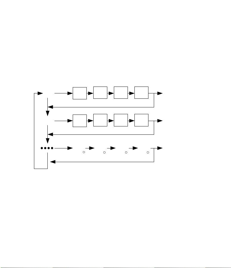
Button Function Legend
Use "SET" key to change value of flashing digit or decimal point
"SET"
Lo
*
Hi
*
*
21
"ENTER"
* * *
* * *
* *
Same time SET
& ENTER
Recalibrate
to the
displayed
value for the
existing Input
Voltage or
Current
*
Page 23
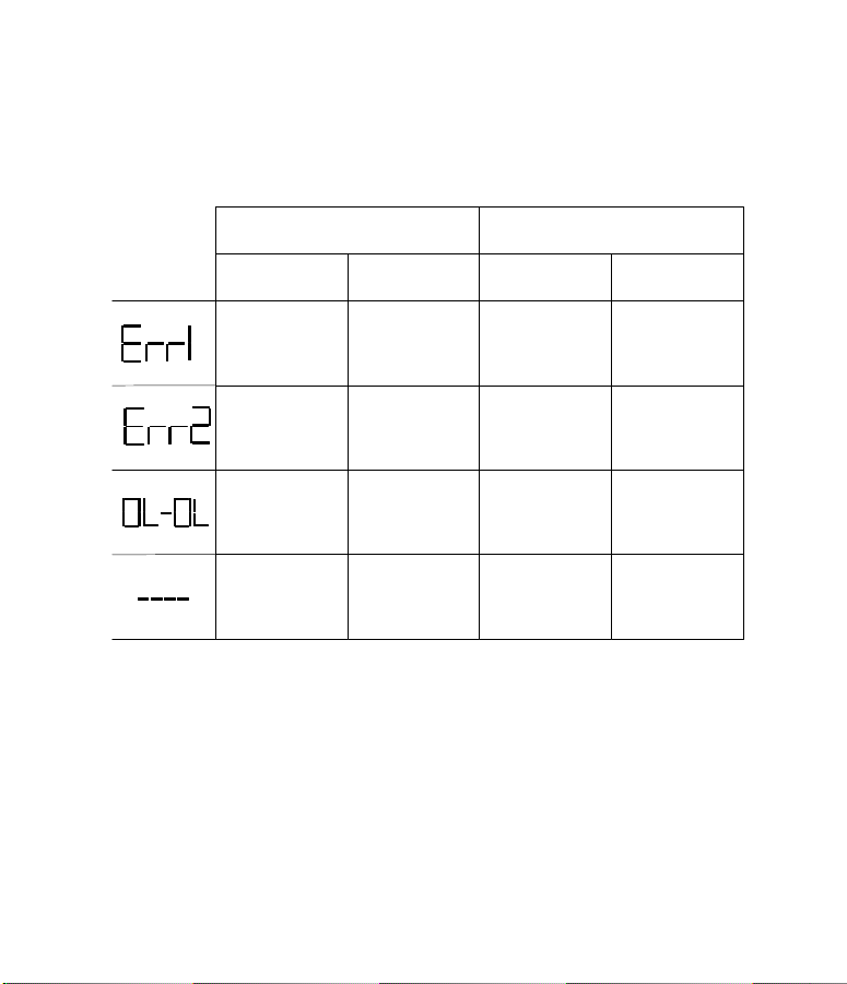
ERROR MESSAGE TABLE
DURING CALIBRATION/
Message
Displayed
SCALING MODE
CAUSE CURE CAUSE CURE
Slope error
Same values
entered for both Hi
and Lo
Slope error. Too
many display
counts for too little
input
Overloaded input or
display. Input
exceeds
specification.
Internal A/D
overload
"Lo" and "Hi" values
must be different.
Push "set" button
and re-enter for "Lo"
and "Hi" values
Push "SET" button.
Reduce number of
counts for given
input.
Check input voltage
or current. Must be
within
0-10 VDC
0-20mA
Turn power off, wait
25 seconds, and
turn power on
again.
22
DURING NORMAL PROCESS
MEASURING MODE
N/A
N/A
Input exceeds
maximum
specifications or
display is beyond
-999 or 9999
Internal A/D
overload
Check input voltage
or current for over
range or open
circuit
Turn power off, wait
25 seconds, and
turn power on
again.
 Loading...