

Page 1
http://www.omega.com
e-mail: [email protected]
U
ser’s Guide
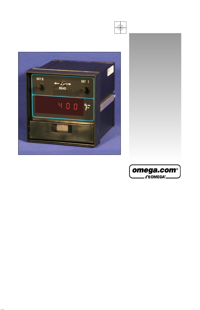
4001A, 4002A, 4201A & 4202A Series
Temperature Controllers
Page 2

USA:
ISO 9001 Certified
Canada:
USA and Canada:
Mexico:
Benelux:
Czech Republic:
France:
Germany/Austria:
United Kingdom:
OMEGAnet®Online Service Internet e-mail
www.omega.com [email protected]
Servicing North America:
One Omega Drive, Box 4047
Stamford CT 06907-0047
Tel: (203) 359-1660 FAX: (203) 359-7700
e-mail: [email protected]
976 Bergar
Laval (Quebec) H7L 5A1, Canada
Tel: (514) 856-6928 FAX: (514) 856-6886
e-mail: [email protected]
For immediate technical or application assistance:
Sales Service: 1-800-826-6342 / 1-800-TC-OMEGA
Customer Service: 1-800-622-2378 / 1-800-622-BEST
Engineering Service: 1-800-872-9436 / 1-800-USA-WHEN
TELEX: 996404 EASYLINK: 62968934 CABLE: OMEGA
En Espan˜ ol: (001) 203-359-7803 e-mail: [email protected]
FAX: (001) 203-359-7807 [email protected]
Servicing Europe:
Postbus 8034, 1180 LA Amstelveen, The Netherlands
Tel: +31 (0)20 3472121 FAX: +31 (0)20 6434643
Toll Free in Benelux: 0800 0993344
e-mail: [email protected]
Frystatska 184, 733 01 Karvina´, Czech Republic
Tel: +420 (0)59 6311899 FAX: +420 (0)59 6311114
Toll Free: 0800-1-66342 e-mail: [email protected]
11, rue Jacques Cartier, 78280 Guyancourt, France
Tel: +33 (0)1 61 37 2900 FAX: +33 (0)1 30 57 5427
Toll Free in France: 0800 466 342
e-mail: [email protected]
Daimlerstrasse 26, D-75392 Deckenpfronn, Germany
Tel: +49 (0)7056 9398-0 FAX: +49 (0)7056 9398-29
Toll Free in Germany: 0800 639 7678
e-mail: [email protected]
One Omega Drive, River Bend Technology Centre
ISO 9002 Certified Northbank, Irlam, Manchester
M44 5BD United Kingdom
Tel: +44 (0)161 777 6611 FAX: +44 (0)161 777 6622
Toll Free in United Kingdom: 0800-488-488
e-mail: [email protected]
®
®
®
Page 3

Introduction
temperature controller.
It is a U.L. listed, 1/4-DIN digital indicating temperature controller for use
-
errors and operator interpolation, problems common to full scale analog
damage that may have occurred in shipping. Save all packing materials
Congratulations on your purchase of an Omega
®
in a variety of applications. These units are more accurate than an ana
log unit, and, most importantly, the digital indicator eliminates parallax
controllers.
If you have questions or require any assistance with your controller or
with any temperature control problem, please contact your Omega representative or call customer service at 1-800-622-2378. In Mexico and
Latin America, please call (95) 800-TC-OMEGASM.
After unpacking, inspect the instrument for any physical
and report any damage to the carrier immediately.
©Copyright 2004, OMEGA ENGINEERING, INC.
Page 4

Output Configurations
1
1
2
3
5
6
6
6
8
9
10
12
12
15
19
19
Preliminary Instructions
Mounting
Power Wiring Circuits
Thermocouple Wiring Circuits
RTD Wiring Circuits
Thermocouple Placement
Operation
Front Panel Layout
Output Function Switches
Adjustments
Maintenance
Specifications
Troubleshooting
Warranty
Unit Repairs
Page 5

Field Conversion
P/N DESCRIPTION
R Relay with 7 A at 120 V and 5 A at 240 V
contacts, on-off and time proportioning
4001-F1 Signal current, 4-20 mAdc
T Solid state relay 1 A, 120/240 V resistive
load; 1 A, 120/240 V, 10 A inrush,
inductive load
4001A-DC Pulsed 20 Vdc, for driving solid state
relays
Unpacking
Carefully unpack the instrument, inspect for shipping damage.
Report any damage to the carrier immediately.
Locating
Select a location for the controller where it will not be subjected to
excessive shock, vibration, dirt, moisture or oil. The ambient temperature of the area should be between 30° and 130° F. (Dust, oil,
water resistant cover is available to protect from harsh environments. Contact factory for details.)
1
Page 6
Mounting
mounting slides, and then remove the slides. Insert case from front
of panel and reinstall the two slides and two screws. The length of
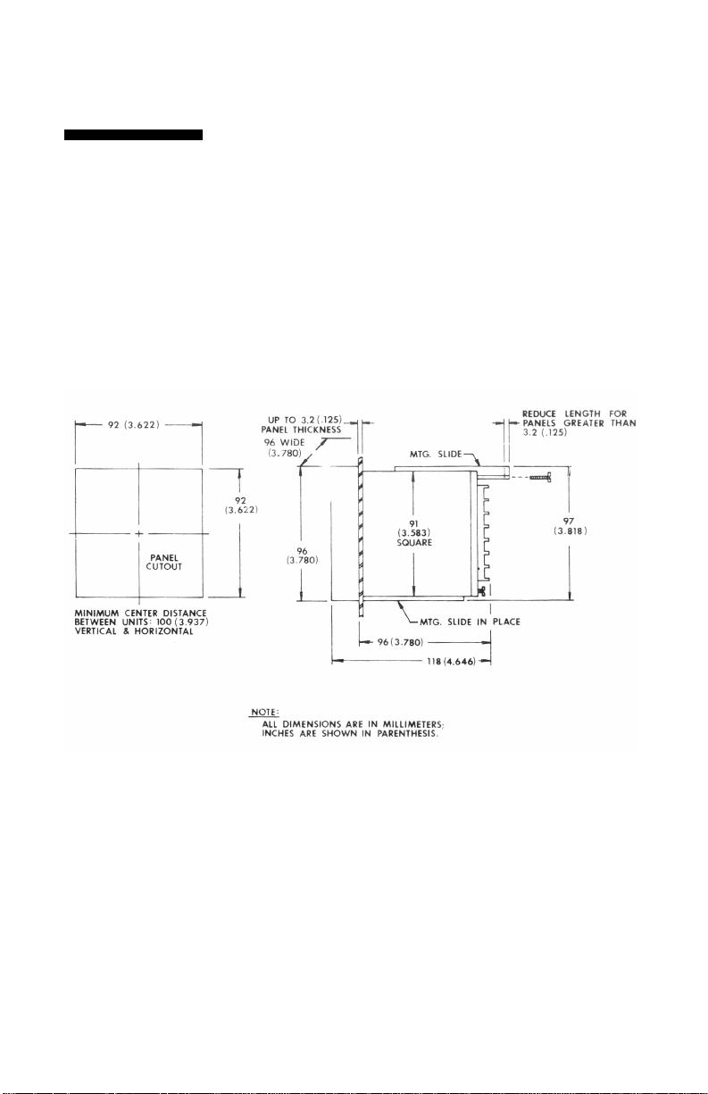
Mount controller into 92 mm (3-5/8”) square cutout (1/4- DIN). See
Figure 1 for cutout and case dimensions. The plug-in controller
does not have to be removed from its housing for mounting.
Remove the two screws in the back of the case that hold the
the slides must be reduced if the controller is to be mounted in an
extra thick panel. If the controller has been unplugged from its
housing, the top of the housing can be determined by the serial
number tag.
Figure 1: Cutout and case dimensions
2
Page 7
Power Wiring
the back of the case. Screw terminals are provided. Make appropri
-
3 A at 120 V and 1.5 A at 240 V. The N.C. contacts can be used for
For 240 Vac supply move connection shown on terminal 9 to
Circuits
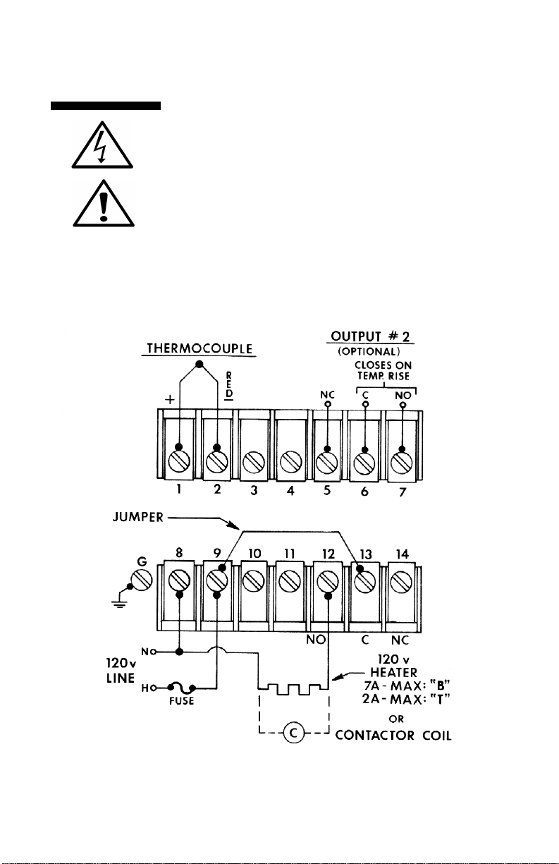
Consult serial tag on the unit and select power wiring diagram for
the model specified. All wires are connected to the terminals on
ate connections using proper size wire for rated controller load
power circuits. (On -B output model use AWG #14 wire; for -F, -S
and -T outputs use #14, 16, or 18 wire.) The unit can be supplied
with 120 V or 240 Vac, 50/60 Hz. Select proper terminal for the
voltage used.
Typical Wiring Diagrams
-T & -B Outputs - 120 Vac
B-Type - 840 W maximum. 120 Vac heater. (Non-inductive loads
only) For larger loads replace heater connections with contactor,
as required o. Maximum inductive load rating is
cooling.
Note:
terminal 10 and fuse both of the supply legs.
Figure 2: Typical 120 Vac for -B & -T Output
3
Page 8
The -T units can handle contactors or resistive loads up to 1 A with
10 A inrush maximum. For -T units use a 1 A, 250 V fast blow fuse.
Maximum load resistance is 1000 ohms. The -DC output is a time-
proportioned 20 Vdc signal. These controllers cannot be used with
a device that does not have an isolated input. An ungrounded ther
-
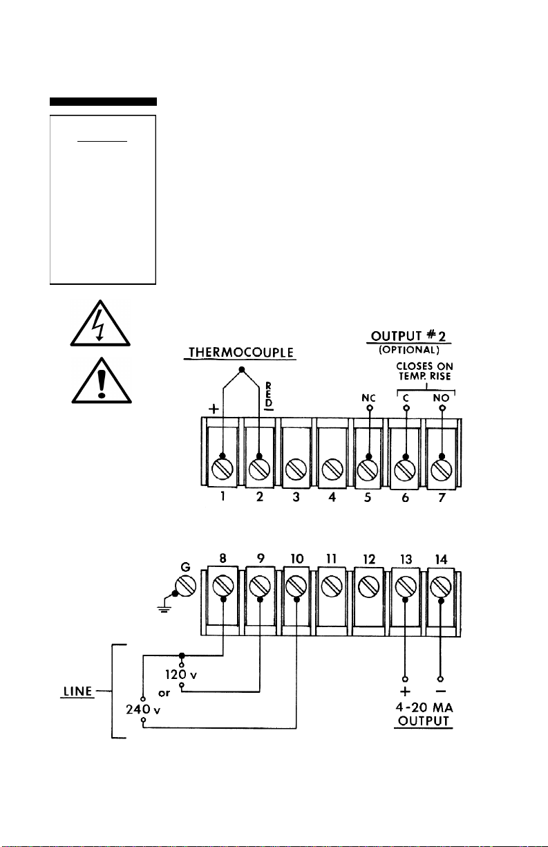
NOTE: For 240 Vac supply move connection shown on terminal 9 to
CAUTION
Possible fire hazard.
Because these controls or associated
equipment may not
always fail safe, an
approved temperature and/or pressure
safety control should
be used for safe
operation.
T-Type - solid state relay with SPST contacts.
-F, -DC Output - 120/240 Vac
The -F output is 20 mA at the low temperature end of the proportional band and 4 mA at the upper end of the proportional band.
mocouple must be used if there is ac leakage or a ground in the
input of the device connected to the controller’s output.
terminal 10 and fuse both of the supply legs.
Figure 3: Typical 120/240 Vac for -F and -DC Output
4
Page 9

Thermocouple
-
wires must be of sufficient size so that on long runs the thermocou
-
Wiring Circuits
Use thermocouple and extension wire that conforms to the appro
priate thermocouple type specified on the serial number tag. In
thermocouple circuits, the negative lead is colored red. Extension
ple circuit resistance does not exceed 100 ohms.
Do not run thermocouple leads in the same conduit as the power
lines. If shielded thermocouple wire is used, terminate the shield
only at the controller end using the corner screw provided for that
purpose.
Standard Thermocouples
I.S.A. Type Materials Color Code (U.S.A.)
J Iron-Constantan (I/C) White (+)/Red(-)
K Chromel-Alumel (C/A) Yellow (+)/Red (-)
T Copper-Constantan Blue (+)/Red (-)
5
Page 10

-
-
The “B” output is a relay rated at 7 A, 120 Vac and 5 A, 240 Vac. These
-
connected to terminals -1 and -2 with a jumper connecting 2 to 3. Keep
leads short and use heavy gauge copper extension wires if necessary,
and wire gauge should be sufficient that resistance does not exceed 10
If shielded RTD wire is used, terminate the shield only at the controller
-
-
-
-
NOTE: RTDs tend to
6
be shock sensitive and
require extra care in
handling and installation
The 4200 is designed for 100 ohm platinum RTDs. Two-wire RTDs are
to minimize lead resistance. For long runs 3-wire RTD should be used
ohms.
DO NOT RUN RTD LEADS IN THE SAME CONDUIT AS POWER
LINES.
end, using the corner screw provided for that purpose.
Proper thermocouple placement can eliminate many problems in the
system. The probe should be placed so that it can detect any tempera
ture change with little thermal lag. In a process that requires fairly con
stant heat output, the probe should be placed close to the
heater. In processes where the heat demand is variable, the probe
should be close to the work area. Some experimenting with probe loca
tion can often provide optimum results.
In a bath process, the addition of a stirrer will help to eliminate lags.
Since the
thermocouple is basically a point measuring device, putting more than
one thermocouple in parallel will provide an average temperature read
ing and produce better results in air-heated processes.
The typical control system contains the sensor, controller (4000) and
the process (load). The sensor produces a small signal proportional to
the measured temperature of the process. This signal is amplified by
the controller, where it is compared with setpoint temperature. If the
temperature of the sensor is below setpoint, the output circuitry will be
actuated to apply power to the process. This is indicated by means of
an LED light. The digital meter displays the sensor’s (process) temper
ature, and when switched to right or left, the primary or secondary con
trol setpoints.
Relay Output
contacts can be wired to provide power to a heater within the above
rating. A contactor can be operated to handle a larger load. Solenoids
can be operated to control oil or gas heaters.
The controller operates as a narrow band controller when the band
adjustment is set at the narrow position. As the band is widened, the
unit becomes a time-proportioning controller, which provides close tem
perature control. The percentage of the time when the relay is energized is varied by the controller to meet the load requirements.
Maximim cycle time setting is 15 seconds.
Page 11

Operation
-F - Current Output
Current proportional output of the -F unit is a 4 to 20 mAdc signal
into 1000 ohm maximum. This output can be used to drive power
controllers, motor positioners or electropneumatic actuators.
-DC - Pulsed Voltage Output
This output is similar to the -F output with the exception of a pulsed
time base rather than a fully proportional current output signal. This
output is designed to drive solid state contactors.
-T - Solid State Output
The -T output unit has a solid state relay with SPST contacts rated
at 1 A, 120/240 Vac (10 A inrush maximum). These contacts can be
wired to provide power to a heater within the above ratings, and a
contactor can be added to handle larger loads. Solenoids can be
operated to control oil or gas heaters.
7
Page 12
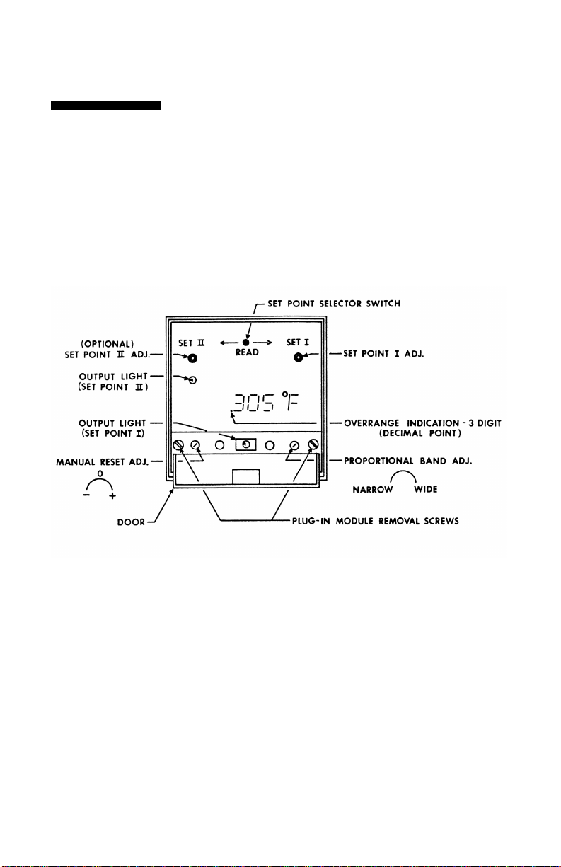
Layout of the front panel is shown below. To reach the adjustments,
swing the top of the door forward and down. The proportional band
adjustment is on the right side and sets the gain of the controller.
The offset (manual reset) adjustment is on the left and corrects for
offsets from the setpoint temperature. The output indication (LED)
can be seen through a window in the door.
Units ordered with Option A (3-Mode PID) will not have a manual
reset adjustment. Instead, these units have an automatic rate and
reset selector switch on the internal 3-mode board.
8
Page 13
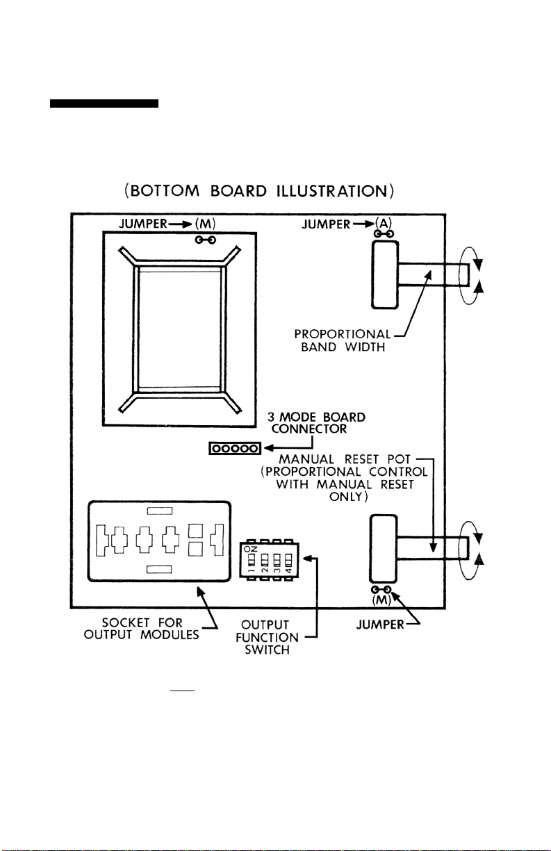
Output Function Switch Chart
(BOTTOM BOARD ILLUSTRATION)
NOTE:
—SWITCH NO. 4 IN “ON” POSITION IS FOR: “B” OR “T” OUTPUTS WHEN
DRIVING MECHANICAL DEVICES, E.G., CONTACTORS.
—SWITCH NO. 4 IN “OFF” POSITION IS FOR “T”, “F”, OR “S” OUTPUTS WHEN
DRIVING DEVICES THAT CAN WITHSTAND RAPID CYCLING, E.G., SOLID
STATE DEVICES, SOLENOIDS, ETC.
9
Page 14

-
Too wide a band can cause an error between the setpoint and the actual
swings just stop. When adjusting the proportional band control, do so in
Turning the adjustment in a clockwise direction widens the proportional
Output Function
There is a switch assembly on the bottom board (see bottom board illus
-
-
These switches act together to select either proportional
times. (See the output function switch chart.) Use longest
Selects either on/off or proportional action. “On” provides
Selects output for either mechanical or solid state relays.
Provides 20 mAdc when used with the “F” module or
fast time proportioning times when used with “S” or
NOTE: Reconfigured
Switches
How to Configure Output Function Switches
or field-modified units
should always be
checked to assure that
output switch positions
are correct.
Adjustments
tration). This four-position switch regulates cycle time and output selec
tion. It is factory-configured for the plug-in output ordered. Check the
output function chart to make sure the configuration is correct for your
application. Figure 5.
Switches 1&2:
current output or one of the time proportioning cycle
times to get best relay life expectancy. If meter shows
temperature swings following each “on” cycle, select a
faster time to reduce “ripple.”
Switch 3:
proportional action. “Off” provides on/off action.
Switch 4:
On: Provides slow proportional times for mechanical
relays
Off:
“T” modules.
NOTE: Switch 4 changes the cycle times in conjunction with switches 1
and 2. Check output function switch chart.
Proportional Band Adjustments for All Outputs
The proportional band adjustment widens or narrows the band over
which proportional action occurs. Too narrow a band can cause the tem
perature to swing about the setpoint. This can be seen on the display.
temperature (droop error) as measured at the sensor.
Proper setting of this adjustment is the point where the temperature
small increments, allowing time between each adjustment for the
process to stabilize.
band and should reduce swings to straight line control with most
processes.
10
Page 15

Adjustments
After the proportional band is set, the process display temperature may sta
-
bilize at a point other than the setpoint, high or low, as shown on the display.
play indicates a low temperature, turn the offset (manual reset) adjustment
some automatic droop compensation can be achieved by cutting jumper “A”
-
perature, or large load changes, will require readjustment of the proportional
#3 to off and cutting the jumper next to the manual reset pot. (See Figure 5.)
The full scale auxiliary output is triggered when temperature goes above its
trip point in either actual or deviation degress, whichever applies. The output
Offset (Manual Reset)
This can be corrected with the offset (manual reset) adjustment. If the dis-
clockwise (+ direction) until the display is correct. Turn the offset (manual
reset) adjustment counter-clockwise (- direction) for high temperature as
indicated by the display.
For applications requiring multiple setpoints over wide temperature spans,
(See bottom board diagram for location, Figure 5).
NOTE: If close control cannot be obtained after carefully repeating the
above procedures, check to see if the thermocouple probe is in good contact with the heated process, and if the heaters are correctly sized for the
application. Applications involving large changes in setpoint operating tem
band and offset (manual reset) pots.
Dead Band
An adjustable 0 to 5 degree deadband can be accessed by setting switch
The band can be adjusted using the proportional band adjustment.
Full Scale Type: E
setting. The setting can be placed
anywhere within the span of the unit.
Setting
To set either type or auxiliary output press and hold the “read” switch to the
left. The display will indicate the present setting. Adjust set II to the desired
on terminals 5, 6, and 7 will be energized when the auxiliary setting is
exceeded.
11
Page 16

120/240 Vac, +10% -15%, 50/60 Hz
Maximum error +/- 1 deg C with 240
mode signal between sensor input
Up scale standard. Zero output for
1000 ohms for rated accuracy; cold
1000 ohms (0 deg C) Platinum. DIN
Some simple preventive maintenance steps on the controllers are:
Keep the controller fairly clean, and protect it from dirt,
oil, and corrosion. An optional dust cover is available for
1.
use in hostile environments.
2. Periodically recheck all electrical connections.
CAUTION: Since the front panel and the meter face are plastic, do
not use solvents to clean them.
Specifications
Line Voltage:
Power Consumption: Less than 5 VA
*Common Mode Rejection:
Vac, 60 Hz applied as a common
and chassis ground
*Series Mode Rejection: Maximum error +/- 1 deg C with
series mode signal of 100 mV pkto-pk at 60 Hz
Sensor Break Protection:
open sensor
Thermocouple: Maximum lead resistance
junction compensation standard
RTD:
coefficient standard
12
Page 17

Setpoints:
Momentary switch displays Set I or Set
II (optional). 25-turn pot provides 1° or
ver full span and deviation alarm
(-B, -C, -D) adjustable +/-0.5% to
a. T/C input +/-0.4% of span over 10%
a. T/C input 3 µV/° F ambient to input
ings per second update; readability is
0.1° settability, range dependent:
Set I - Adjustable over full span;
Set II - Process alarm (-E) adjustable
+/-5% of span.
Setpoint Repeatability: +/-0.1% to +/-0.2% of span
Setpoint Resolution: 1° or 0.1°
Calibration Accuracy:
to 90% of range
b. RTD inputs +/-0.1% of span for 1° F
or 1° C ranges; +/-0.2% of span for
0.1° F or 0.1° C ranges
Ambient Stability:
b. RTD input 0.1% for 80° to 130° F
Process Indication: Filtered LED, 3 or 3-1/2 digits. 2 read-
1° F, 1° C, 0.1° F or 0.1° C, range
dependent
Dimensions: See Figure 1
Weight: Less than 2 lb (0.9 kg)
All specifications subject to change.
13
Page 18

Output Type Setpoint I (Plug-In) Setpoint II
Output
Proportional
Band
Output Cycle
Time (Switch
Selectable)
Manual Reset
(Offset)
Optional
3-Mode (PID)
Action
Differential
Indication
Operating
Ambient
SPDT
T DC F
SPST SS
relay
relay, zero
resistive
voltage
load rating:
switched
7 A @120
1 A @
V; 5 A @
120/240
240 V;
Vac, 10 A
50 VA
inrush,
inductive
2-4 mA
leakage
Adjustable for .2 to 5% of span
on-off
0.5-1.0-1.5
5-10-15
5-10-15
seconds
seconds
Standard — adjustable for full proportional bandwidth (eliminated if PID is ordered)
Fast = 3 sec rate, 0.8 min. reset;
Medium = 21 sec rate, 1.5 min. reset;
Slow = 68 sec rate, 5 min. reset
0-5° adjustable
Red LED “ON” when output signal is present or
relay is energized
4-20
Pulsed dc
mAdc into
for driving
1000 ohm
Solid State
max; not
contactors
isolated
0-20 V,
from TC
open ckt;
0-20 mA
short ckt;
not isolated from
TC
0.5-1.0-1.5
Continuous
seconds
proportioning
30° to 131° F (0-55° C)
SPDT relay 3A
@ 120 Vac
resistive
(4000 only)
on/off (see
differential
below)
Not applicable
Not applicable
Not applicable
+/-1° F or
+/-1° C
Red LED “ON” when relay is
energized
SPDT relay
3A @ 120
Vac resistive
on/off (see
differential
below)
1% maximum
of unit span
14
Page 19

Troubleshooting
Symptom
1. Controller dead. No output light, no digital display
Probable Cause
- No line voltage input
- Open PC board to backplate connector (defective connector)
- Open power transformer
2. No output, step 1 ok, display reads ambient
3. No output
4. a. Full output, no control. Power light stays on.
4. b. Full output, no control. Power light goes off.
5. Process control temperature differs from setpoint when
read with an external pyrometer. Controller’s display agrees
with setpoint.
6. Temperature overshoots, or oscillates.
7. Process control temperature stabilizes above or below setpoint as read on display.
- External backplate jumper missing (all models except
“S” and “F”)
- Defective relay
- Open heater or heater circuit wiring
- Open thermocouple or T/C wiring
- Thermocouple connections reversed
- T/C lead wires shorted between T/C and control
- Relay contacts welded closed
- T/C lead wires shorted close to process
- Wrong type of T/C being used, etc.
- Standard electrical wiring being used in place of T/C
wire
- Gradient error
- Process overpowered
- Bandwidth too narrow
- Process or sensor lag
- Offset (manual reset) incorrectly adjusted
- Partial short to ground in heater when used on
240 V line
- No output from suspect control
- Controller reading other zones of multi-controlled
process
- Full output from suspect control
- Apparent stabilization from other zones of multi-controlled process
- Improperly sized heater
15
Page 20

Check
Verify 120/240 Vac, 50/60 Hz input voltage. Check heater for shorts. Look for open breakers or
open external fuse.
Check continuity through power transformer primary. Remove input power. With ohmmeter, read
between pins: 8 and 9 for 225 or 450 ohms +/-10% and 8 and 10 for 680 or 1000 ohms +/-10%
If no readings in either step above, remove controller from housing and repeat resistance measurements as above, but directly on PC board lands corresponding to pins 8, 9, and 10. Correct
readings indicate open PC board to backplate connector problem. Incorrect readings indicate
power transformer problems.
Corrective Action
- Replace heater, if shorted
- Restore power
- Replace either power transformer or backplate connector
Refer to wiring diagram.
Visually inspect relay contacts.
Heater continuity and wiring.
T/C continuity. Disconnect T/C connections from instrument. Measure T/C circuit resistance.
Ohmmeter should read 100 ohms or less.
Connection polarity. T/C wires are color-coded. Red is the negative (-) lead. (for U.S.A.)
T/C lead wiring.
Disconnect power and load. Measure resistance between pins 12 and 13. Should read infinity.
Check T/C lead wires at back of probe
Wire color indicates type of T/C
Verify type of wire
Check out above three items first
Compare “on time” to “off time.” Short on to off time
indicates too much heater capacity for the process
Check bandwidth
Loose heater or sensor fit. Poor relative location.
Offset (manual reset)
Heater to ground resistance
See symptom 2 (no output)
- Install jumper
- Replace relay if contacts are worn or dirty
- Replace open heater, correct defective wiring
- Replace T/C. Correct defective wiring
- Connect correctly
- Repair or replace
- If resistance reading is near 0 ohms, replace relay
- Replace defective wiring
- Install correct T/C for temperature range of instrument. See instrument serial number tag for T/C type.
- Run only T/C wire between process and controller.
- Use electronic indicator in parallel with suspect instrument’s T/C
input.
- Reduce total heater power
- Widen band
- Improve fit, locate closer together
- Adjust (+) to increase controlled temp. (-) to decrease temp.
- Replace defective heater
NOTE: Fuse blowing is not caused by the controller. Blown fuses are
caused by shorts in the heater circuit, and must be corrected to prevent damage to the controller.
See symptom 4 (full output)
Design parameters for process heat required
16
Page 21

NOTES:
17
Page 22

NOTES:
18
Page 23

BEFORE RETURNING ANY PRODUCT(S) TO OMEGA, PURCHASER MUST OBTAIN AN
AUTHORIZED RETURN (AR) NUMBER FROM OMEGA’S
CUSTOMER SERVICE DEPARTMENT (IN ORDER TO AVOID PROCESSING DELAYS). The
assigned AR number should then be marked on the outside of the return package and on any corre
-
OMEGA’s policy is to make running changes, not model changes, whenever an improvement is pos
-
sible. This affords our customers the latest in
© Copyright 1995 OMEGA ENGINEERING, INC. All rights reserved. This
documentation may not be copied, photocopied, reproduced, translated,
or reduced to any electronic medium or machine-readable form, in whole or in part, without prior writ
-
WARRANTY / DISCLAIMER
OMEGA ENGINEERING, INC. warrants this unit to be free of defects in materials and workmanship
for a period of 25 months from date of purchase. OMEGA Warranty adds an additional one (1)
month grace period to the normal two (2) years product warranty to cover handling and shipping
time. This ensures that OMEGA’s customers receive maximum coverage on each product. If the unit
should malfunction, it must be returned to the factory for evaluation. OMEGA’s Customer Service
Department will issue an Authorized Return (AR) number immediately upon phone or written
request. Upon examination by OMEGA, if the unit is found to be defective it will be repaired or
replaced at no charge. OMEGA’s WARRANTY does not apply to defects resulting from any action of
the purchaser, including but not limited to mishandling, improper interfacing, operation outside of
design limits, improper repair, or unauthorized modification. This WARRANTY is VOID if the unit
shows evidence of having been tampered with or shows evidence of being damaged as a result of
excessive corrosion; or current, heat, moisture or vibration; improper specification; misapplication;
misuse or other operating conditions outside of OMEGA’s control. Components which wear are not
OMEGA is glad to offer suggestions on the use of our various
products. Nevertheless, OMEGA only warrants that the parts
OMEGA MAKES NO OTHER WARRANTIES OR REPRESENTATIONS OF ANY KIND
WHATSOEVER, EXPRESSED OR IMPLIED, EXCEPT THAT OF TITLE, AND ALL IMPLIED
WARRANTIES INCLUDING ANY WARRANTY OF MERCHANTABILITY AND FITNESS FOR A
LIMITATION OF LIABILITY: The remedies of purchaser set forth herein are exclusive and the total
liability of OMEGA with respect to this order, whether based on contract, warranty, negligence,
indemnification, strict liability or otherwise, shall not exceed the purchase price of the component
upon which liability is based. In no event shall OMEGA be liable for consequential, incidental or
Every precaution for accuracy has been taken in the preparation of this manual; however, OMEGA
ENGINEERING,INC. neither assumes responsibility for any omissions or errors that may appear not
assumes liability for any damages that result from the use of the products in accordance with the
CONDITIONS: Should this equipment be used in or with any nuclear installation or
activity, purchaser will indemnify OMEGA and hold OMEGA harmless from any liability or damage
warranted, including but not limited to contact points, fuses, and triacs.
manufactured by it will be as specified and free of defects.
PARTICULAR PURPOSE ARE HEREBY DISCLAIMED.
special damages.
information in the manual.
SPECIAL
whatsoever arising out of the use of the equipment in such a manner.
RETURN REQUESTS / INQUIRIES
spondence.
technology and engineering.
OMEGA is a registered trademark of OMEGA ENGINEERING, INC.
ten consent of OMEGA ENGINEERING, INC.
19
Page 24

Where Do I Find Everything I Need for
Process Measurement and Control?
“B”
M-0049 / 1299 (DP 2/2002 1.0)
OMEGA…Of Course!
TEMPERATURE
-
Thermocouple, RTD & Thermistor Probes,
Connectors, Panels & Assemblies
-
Wire: Thermocouple, RTD & Thermistor
-
Calibrators & Ice Point References
-
Recorders, Controllers & Process Monitors
-
Infrared Pyrometers
PRESSURE, STRAIN
AND FORCE
-
transducers & Strain Gauges
-
Load Cells & Pressure Gauges
-
Displacement Transducers
-
Instrumentation & Accessories
FLOW/LEVEL
-
Rotameters, Gas Mass Flowmeters
& Flow Computers
-
Air Velocity Indicators
-
Turbine/Paddlewheel Systems
-
Totalizers & Batch Controllers
pH/CONDUCTIVITY
-
pH Electrodes, Testers & Accessories
-
Benchtop/Laboratory Meters
-
Controllers, Calibrators, Simulators
& Pumps
-
Industrial pH & Conductivity Equipment
DATA ACQUISITION
-
Data Acquisition &
Engineering Software
-
Communications-Based
Acquisition Systems
-
Plug-in Cards for Apple, IBM
& Compatibles
-
Datalogging Systems
-
Recorders, Printers & Plotters
HEATERS
-
Heating Cable
-
Cartridge & Strip Heaters
-
Immersion & Band Heaters
-
Flexible Heaters
-
Laboratory Heaters
ENVIRONMENTAL
MONITORING AND CONTROL
-
Metering & Control Instrumentation
-
Refractometers
-
Pumps & Tubing
-
Air, Soil & Water Monitors
-
Industrial Water & Wastewater
Treatment
-
pH, Conductivity & Dissolved
Oxygen Instruments
900M047U00 REVISION
 Loading...