

Page 1
IMMERSION SERIES
Installation & Operation Instructions
PRECAUTIONS
•DO NOT RUN THE WIRING IN ANY CONDUIT
WITH LINE VOLTAGE (24/120/230 VAC).
GENERAL INFORMATION
The Immersion sensor is a single point
temperature sensor that is designed for use with
electronic controllers in commercial heating
and cooling building management systems.
It is available with multiple thermistor or RTD
options.
For optimal temperature readings, follow
these tips:
• Apply thermal grease to the end of the
probe before installation into thermowell
(ACI Item #102595).
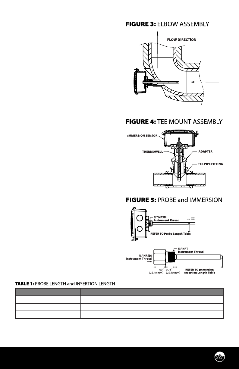
• The tip of the thermowell should be
located in the middle of the pipe.
• The sensor thermowell should be installed
against the flow of the water, where
water temperature is well mixed (no
stratification).
• Make sure the entire thermowell is
immersed. If the thermowell is longer than
the pipe diameter, the thermowell should
be installed in an elbow or Tee.
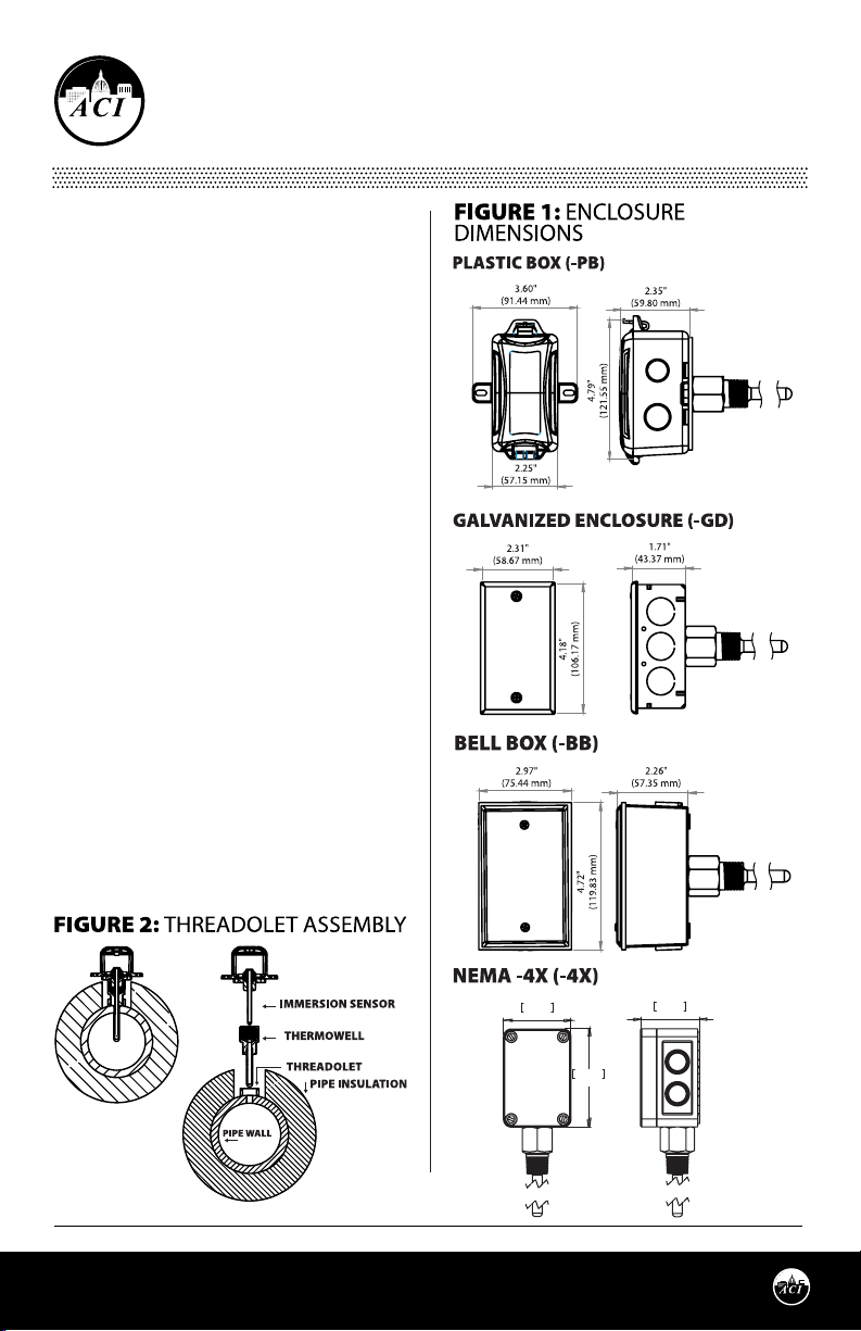
THERMOWELL INSTALLATION
ACI’s standard Immersion sensors are made to
install into a ½” NPT female thread. Typically a
Threadolet or Tee is installed into the pipe, but a
hole can also be drilled and tapped.
Phone: 1-888-967-5224
Website: workaci.com
Automation Components, Inc.
2305 Pleasant View Road | Middleton, WI 53562
Phone: 1-888-967-5224 | Website: workaci.com
Page 1
64.8mm64.8mm
2.550in2.550in
94.0mm94.0mm
3.700in3.700in
56.7mm56.7mm
2.233in2.233in
Version: 4.0
I0000811
Page 2
THERMOWELL INSTALLATION
The pipe/system will need to be drained, unless a
Hot Tap is being used. The recommend drill size is
23/32 in. (18 mm). Drill the hole, and tap the hole
with ½”-14NPT.
Always use proper thread sealants on tapered
pipe threads of the thermowell. Screw the
thermowell into the Threadolet, Tee, or tapped
hole, using a wrench to tighten it rmly. Rell the
system and check for leaks.
Best practice is to apply thermal grease to the
end of the probe, but not required. Insert and
push the sensor probe into the thermowell.
Turn the sensor probe assembly clockwise
to tighten down completely. Refer to the
Wiring Instructions (p. 2-3) to make necessary
connections.
PROBE INSERTION
The immersion sensors “-I” include a welded
thermowell but can be ordered without the
thermowell “-INW” version. The “-INW” includes a
standard ½” NPS process thread to be used with
a machined thermowell or previously installed
thermowell. Verify the existing thermowell
insertion length of the pipe is suitable for your
selected Immersion.
If the length of the probe is too large, the probe
may be pressed into its enclosure - up to an inch
of clearance.
Note: *Fabricated (welded) thermowells (-I) are
not intended for moving water or high pressure
service. Fluid velocity and wake frequency
are primary factors in well failure. Machined
thermowells (-IM) should be used in these types
of applications. Fabricated thermowells are
intended for tank, or low to no ow, applications.
ACI PART # IMMERSION LENGTH PROBE LENGTH
A/xx-I-2.5”-yy-zz 2.5” (63.50 mm) 4.31” (109.47 mm) +/- 0.13” (3.30 mm)
A/xx-I-4”-yy-zz 4.0“ (101.60 mm) 5.81“ (147.57 mm) +/- 0.13” (3.30 mm)
A/xx-I-6”-yy-zz 6.25” (158.75 mm) 7.81” (198.37 mm) +/- 0.13” (3.30 mm)
Page 2
Automation Components, Inc.
2305 Pleasant View Road | Middleton, WI 53562
Phone: 1-888-967-5224 | Website: workaci.com
Version: 4.0
I0000811
Page 3
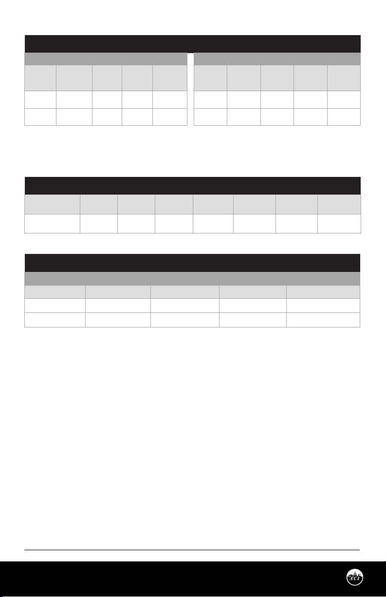
MAXIMUM VELOCITY VS THERMOWELL INSERTION LENGHT MACHINED THERMOWELL
Straight Shank Insertion Length "U" Stepped Shank Insertion Length "U"
Material: Media Type:
304/316 SS Air/Gas/Steam
304/316 SS Water
Note: Values are for Air/Gas/Steam and similar density media based upon Max pressure of 2900 PSI @ 1000ºF (537.8ºC) | Note: Values are
for Water (No Glycol or other Chemicals factored in) @ 68 ºF (20ºC) and max pressure of 5700 PSI. (Calculated to ASME PTC 19.3 TW-2016 Code
B31.1) | Note: 6-24” Machined Thermowells meet ASME PTC 19.3 TW-2016 Code B31.1.
1.0"
(25.4 mm)
349 ft/s
(106.3 m/s)
360 ft/s
(109.7 m/s)
2.5"
(63.5 mm)
349 ft/s
(106.3 m/s)
360 ft/s
(109.7 m/s)
8.0"
(203.2 mm)
71.9 ft/s
(21.9 m/s)
71.9 ft/s
(21.9 m/s)
4.0"
(101.6 mm)
109 ft/s
(33.2 m/s)
82.2 ft/s
(25.1 m/s)
6.0"
(152.4 mm)
73.6 ft/s
(22.4 m/s)
26.9 ft/s
(8.2 m/s)
12.0"
(304.8 mm)
19.4 ft/s
(5.9m/s)
11.3 ft/s
(3.4m/s)
18.0"
(457.2 mm)
8.8 ft/s
(2.7m/s)
4.7 ft/s
(1.43m/s)
24"
(609.6 mm)
5.2 ft/s
(1.6m/s)
2.5 ft/s
(0.8m/s)
MAXIMUM PRESSURE VS TEMPERATURE RATINGS TWO-PART FABRICATED | WELDED THERMOWELL
Material:
304/316 SS
70°F
(21.1°C)
982 PSI
(67.7 Bar)
200°F
(93.3°C)
820 PSI
(56.6 Bar)
400°F
(204.4°C)
675 PSI
(46.5 Bar)
600°F
(315.6°C)
604 PSI
(41.6 Bar)
800°F
(426.7°C)
550 PSI
(37.9 Bar)
1000°F
(537.8°C)
510 PSI
(35.1 Bar)
1200°F
(648.9°C)
290 PSI
(20.0 Bar)
MAXIMUM FLUID VELOCITY RATINGS TWO-PART FABRICATED | WELDED THERMOWELL
Straight Shank Insertion Length "U"
Material: Media Type: 2.5" (63.5 mm) 4.0" (101.6 mm) 6.0" (152.4 mm)
304/316 SS Air/Gas/Steam 169 ft/s (51.5 m/s) 61 ft/s (18.6 m/s) 20 ft/s (6.1 m/s)
304/316 SS Water 88 ft/s (26.8 m/s) 20 ft/s (6.1 m/s) 10 ft/s (3.05 m/s)
Note: Values are for Air/Gas/Steam and similar density media
WIRING INSTRUCTIONS
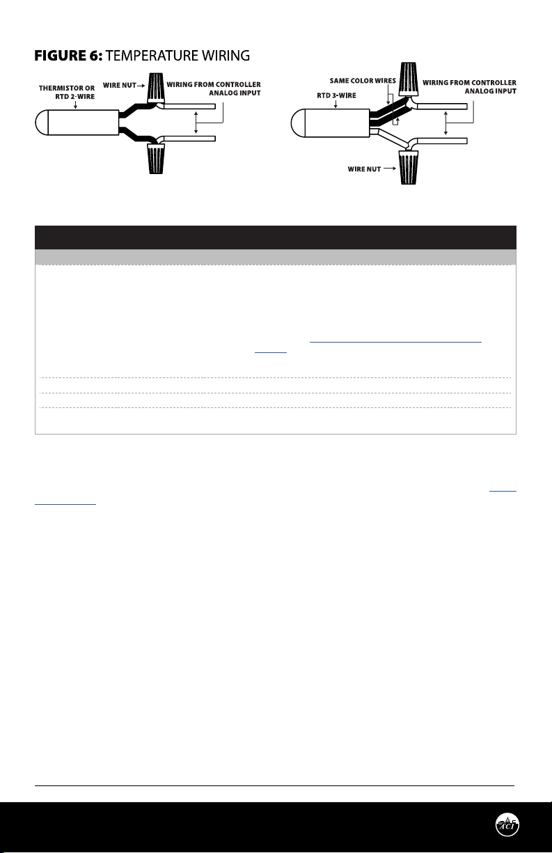
Open the cover of the enclosure. ACI recommends 16 to 26 AWG twisted pair wires or shielded cable
for all sensors. Signal wiring must be run separate from low and high voltage wires (24/120/230VAC).
All ACI thermistors and RTD temperature sensors are both non-polarity and non-position sensitive. All
thermistor type units are supplied with (2) flying lead wires, and all RTD’s are supplied with (2) or (3)
flying lead wires – see FIGURE 6 (pg. 4). The number of wires needed depends on the application.
Connect thermistor/RTD wire leads to controller analog input wires using wire nuts, terminal blocks, or
crimp style connectors. All wiring must comply with all local and National Electric Codes. After wiring,
attach the cover to the enclosure.
Note: When using a shielded cable, be sure to connect only (1) end of the shield to ground at the
controller. Connecting both ends of the shield to ground may cause a ground loop. When removing the
shield from the sensor end, make sure to properly trim the shield to prevent any chance of shorting.
Note: If the controller requires a (2) wire input for a RTD, connect the (2) common wires(same color)
together. If the controller requires (3) wires, use (3) individual wires.
Page 3
Automation Components, Inc.
2305 Pleasant View Road | Middleton, WI 53562
Phone: 1-888-967-5224 | Website: workaci.com
Version: 4.0
I0000811
Page 4
TROUBLESHOOTING
PROBLEM SOLUTION(S)
• Verify sensor wiring to controller is not damaged and has continuity.
• Verify sensor or wires are not shorted together.
• Verify controller is setup for correct sensor curve.
• Disconnect sensor wires, and take a resistance reading with a
Sensor reading is incorrect
Sensor reads innity/very high resistance • Sensor or wires are open
Sensor reads low resistance • Sensor or wires are shorted together
Erratic readings
WARRANTY
The ACI Immersion Series temperature sensors is covered by ACI’s Five (5) Year Limited Warranty, which is
located in the front of ACI’S SENSORS & TRANSMITTERS CATALOG or can be found on ACI’s website: www.
workaci.com.
W.E.E.E. DIRECTIVE
At the end of their useful life the packaging and product should be disposed of via a suitable recycling
centre. Do not dispose of with household waste. Do not burn.
multimeter.
• Compare the resistance reading to the Temperature Vs Resistance
Curves online: http://www.workaci.com/content/thermistor-
curves-0
• Verify proper mounting location to conrm no external factors are
aecting reading.
• Condensation on PCB board
• Bad wire connections
Automation Components, Inc.
2305 Pleasant View Road | Middleton, WI 53562
Phone: 1-888-967-5224 | Website: workaci.com
Page 4
Version: 4.0
I0000811
Page 5
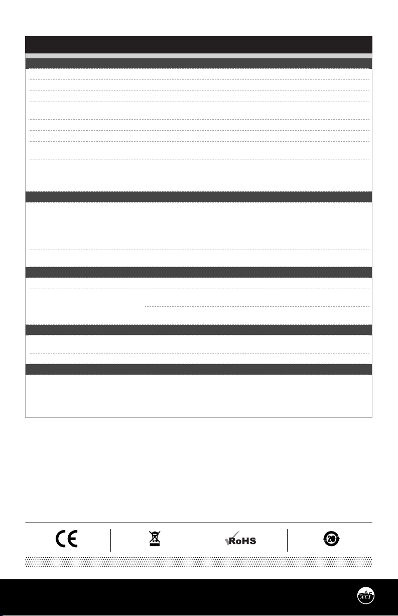
PRODUCT SPECIFICATIONS
SENSOR NON-SPECIFIC
Number Sensing Points: One
Storage Temperature Range: -40 to 85 °C (-40 to 185 °F)
Operating Humidity Range: 0 to 90% RH, non-condensing
Probe Diameter | Thermowell Bore
Diameter:
Probe Material | Thermowell Material: 304 Stainless Steel | 304 Series Stainless Steel
Wire Size 22 AWG (0.65 mm)
Thermowell Instrument | Process Thread
Size:
Enclosure Specications:
(Temperature, Material, Flammability, NEMA/
IP Ratings)
THERMISTOR
Sensor Output @ 25ºC (77ºF):
(Lead Wire Colors)
*Does not include CL2P
Accuracy 0-70ºC (32-158ºF):
PLATINUM
Sensor Output @ 0°C (32°F): A/100: 100 nominal A/1K: 1 K nominal
Accuracy:
BALCO
Sensor Output @ 21.1 °C (70 °F):
(Lead Wire Colors)
Accuracy: @ 21.1 °C (70 °F): +/- 1%
NICKEL
Sensor Output @ 21.1 °C (70 °F):
(Lead Wire Colors)
Accuracy:
0.250” (6.35mm) | 0.260”
½” NPS (National Pipe Straight) Female Thread | ½” NPT (National Pipe Tapered) Male
Thread
“-GD” Enclosure: Galvanized Steel, -40 to 121 °C (-40 to 250 °F), NEMA 1 (IP10)
“-PB” Enclosure: ABS Plastic, UL94-HB, -30 to 90 °C (-22 to 194 °F), Plenum Rated
“-BB” Enclosure: Aluminum, -40 to 121°C (-40 to 250 °F), Plenum Rated, NEMA 3R (IP 14)
“-4X” Enclosure: Polystyrene Plastic, UL94-V2, -40 to 70°C (-40 to 158°F), NEMA 4X (IP 66)
A/1.8K: 1.8 K nominal (Red/Yellow)
A/3K: 3 K nominal (White/Brown)
A/AN (Type III): 10 K nominal (White/White)
A/AN-BC: 5.238 K nominal (White/Yellow)
A/CP (Type II): 10 K nominal (White/Green)
A/50K: 50K nominal (Brown/Yellow)
A/1.8K Series: +/- 0.5 °C @ 25 °C (77 °F)
and (+/-1.0 °C) (+/-1.8 °F)
+/- 0.06% Class A (Tolerance Formula: +/- °C = (0.15 °C + (0.002 * |t|))
where |t| is the absolute value of Temperature above or below 0 °C in °C)
@ -40 °C (-40 °F): +/- 0.23°C (+/- 0.414 °F)
@ 0 °C (32 °F): +/- 0.15°C (+/- 0.27 °F)
1 K nominal (Orange/Yellow)
1 K nominal (Red/Red)
@ -40 °C (-40 °F): +/- 1.52 °C (+/- 2.73 °F)
@ 0 °C (32 °F): +/- 0.4 °C (+/- 0.72 °F)
@ 21.1 °C (70 °F): +/- 0.17 °C (+/- 0.34 °F)
A/CSI: 10 K nominal (Green/Yellow)
A/10KS: 10 K nominal (White/Blue)
A/10K-E1: 10 K nominal (Gray/Orange)
A/20K: 20 K nominal (Brown/Blue)
A/100KS: 100 K nominal (Black/Yellow)
A/10K-E1 Series: +/- 0.3 °C (+/- 0.54 °F)
All Else: +/- 0.2 °C (+/- 0.36 °F)
@ 200 °C 392 °F): +/- 0.55 °C (+/- 1.00 °F)
@ 54.4 °C (130 °F): +/- 0.56 °C (+/- 1. 00°F)
@ 121 °C (250 °F): +/- 1.25 °C (2.25 °F)
Automation Components, Inc.
2305 Pleasant View Road | Middleton, WI 53562
Phone: 1-888-967-5224 | Website: workaci.com
Page 5
Version: 4.0
I0000811
Page 6
Page 6
Automation Components, Inc.
2305 Pleasant View Road | Middleton, WI 53562
Phone: 1-888-967-5224 | Website: workaci.com
Version: 4.0
I0000811
Page 7
Page 7
Automation Components, Inc.
2305 Pleasant View Road | Middleton, WI 53562
Phone: 1-888-967-5224 | Website: workaci.com
Version: 4.0
I0000811
Page 8
Page 8
Automation Components, Inc.
2305 Pleasant View Road | Middleton, WI 53562
Phone: 1-888-967-5224 | Website: workaci.com
Version: 4.0
I0000811
 Loading...