

Page 1
8
1.5
8
1.5
15
1.0
8
1.5
15
1.0
25
1.5
8
1.5
15
1.0
25
1.5
25
1.0
8
1.5
15
1.0
25
1.5
25
1.0
30
2.6
8
1.5
15
1.0
25
1.5
25
1.0
30
2.6
15
1.5
8
1.5
15
1.0
25
1.5
25
1.0
30
2.6
30
4.5
15
1.5
8
1.5
15
1.0
25
1.5
25
1.0
30
2.6
30
4.5
15
1.5
25
1.5
8
1.5
15
1.0
25
1.5
25
1.0
30
2.6
30
4.5
15
1.5
25
1.5
25
1.7
8
1.5
15
1.0
25
1.5
25
1.0
30
2.6
30
4.5
15
1.5
25
1.5
30
4.5
25
1.7
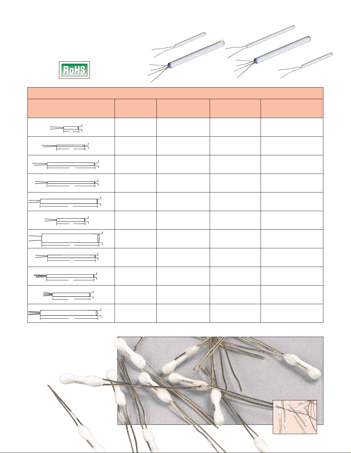
Ceramic Wire-Wound Platinum
RTD Elements
All Models
To Order
Nominal Self-Heating Error in
Dimensions in millimeters Resistance Temperature °C/mW Flowing Air
(1 mm = 0.03937") (ohms) Range, °C (°F) Model No. V = 1m/sec
1.5
8
1.0
1.5
1.0
2.6
1.5
4.5
1.5
1.7
4.5
2.6
15
25
25
30
15
30
25
25
30
Dual elements. All RTD elements come standard with 10 mm bare leads. Welded insulated extension leads available.
*
Pricing is dependent on lead style.
Ordering Examples: 1PT100KN815,
1 x 100 Ω self-heating error
of 0.28 ceramic wire-wound
platinum RTD elements.
1PT100KN1515, 100 Ω, 1.5 D x 15 mm L,
ceramic wire wound RTD.
30
1 x 100
1 x 100
1 x 100
1 x 100
1 x 100
1 x 100
1 x 100
1 x 100
2 x 100
2 x 100
2 x 100
-200 to 600
(-330 to 1110)
-200 to 600
(-330 to 1110)
-200 to 850
(-330 to 1560)
-200 to 600
(-330 to 1110)
-200 to 600
(-330 to 1110)
-200 to 600
(-330 to 1110)
-200 to 600
(-330 to 1110)
-200 to 600
(-330 to 1110)
-200 to 850
(-330 to 1560)
-200 to 600
(-330 to 1110)
-200 to 600
(-330 to 1110)
1PT100KN815 0.28
1PT100KN1510 0.14
1PT100K2515 0.08
1PT100KN2510 0.07
1PT100KN3026 0.04
1PT100KN1515 0.08
1PT100KN3045 0.01
1PT100KN2515 0.07
*2PT100K2517 0.06
*2PT100KN3045 0.01
*2PT100KN3026 0.04
H2104, shown
larger than actual
size.
Actual size.
Page 2
Class B Tolerance (Per IEC751)
Alpha = 0.00385
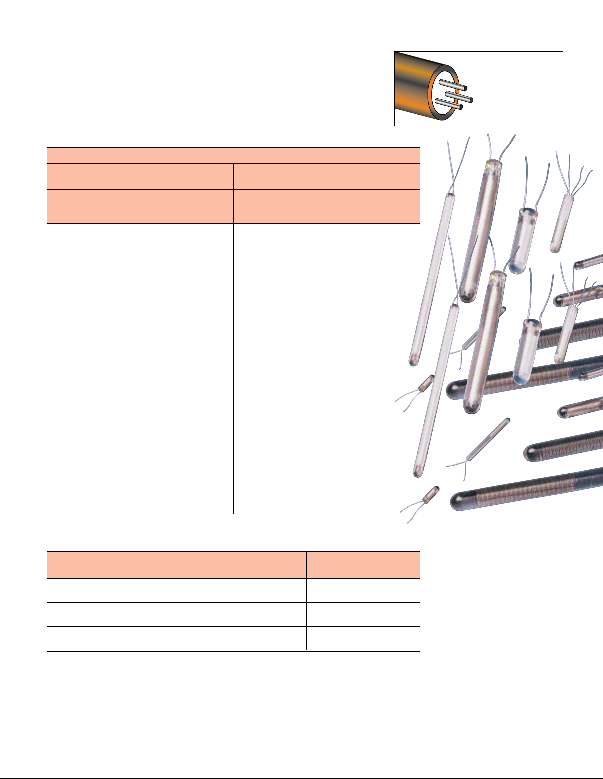
Ceramic wire-wound platinum RTD
elements are made by placing a
coiled platinum wire into a ceramic
core and sealing the ends off
with glass. They are suitable for
extremely low or high temperatures
Response Time in Seconds
Flowing Water Moving Air
V = 0.4 m/sec V = 1 m/sec
50% 90% 50% 90%
Response Response Response Response
0.2 0.5 6.7 21.8
0.2 0.3 3.0 9
0.2 0.4 5.7 17
0.2 0.4 3.0 8.8
and are tolerant of thermal shocks.
They offer limited vibration
resistance (depending on
mounting method) and should be
used in dry environments only.
Available!
OMEGA’s
Available in a wide
selection of conductor
configurations and sheath
materials. Please visit
omega.com.
RTD MI Cable!
0.3 0.6 10.5 34.0
0.2 0.4 5.0 15.7
0.40 1.4 26.0 90.0
0.2 0.4 5.3 16.0
0.2 0.4 6.1 19.0
0.4 1.4 26.8 83.7
0.30 0.6 11 36.0
RTD Elements for Tight Spaces
Model Temperature Nominal Resistance
Number Range (Ω) Dimensions
A2105* -50 to 400°C 1 x 100 2 L x 2.4 W x 2 mm D
(-60 to 750°F) (0.08 x 0.09 x 0.08")
A2132* -50 to 400°C 1 x 500 4 L x 5 W x 2 mm D
(-60 to 750°F) (0.16 x 0.20 x 0.08")
A2142* -50 to 400°C 1 x 1000 4 L x 5 W x 2 mm D
(-60 to 750°F) (0.16 x 0.20 x 0.08")
Enlarged to show construction.
See previous page for dimensions.
These elements have leads perpendicular to the body for surface measurements.
*
Curve is European } = 0.00385. All RTD elements available with welded PTFE insulated extension
Ordering Examples: A2142, 1000 Ω, 4 x 5 mm RTD element.
 Loading...