

Page 1
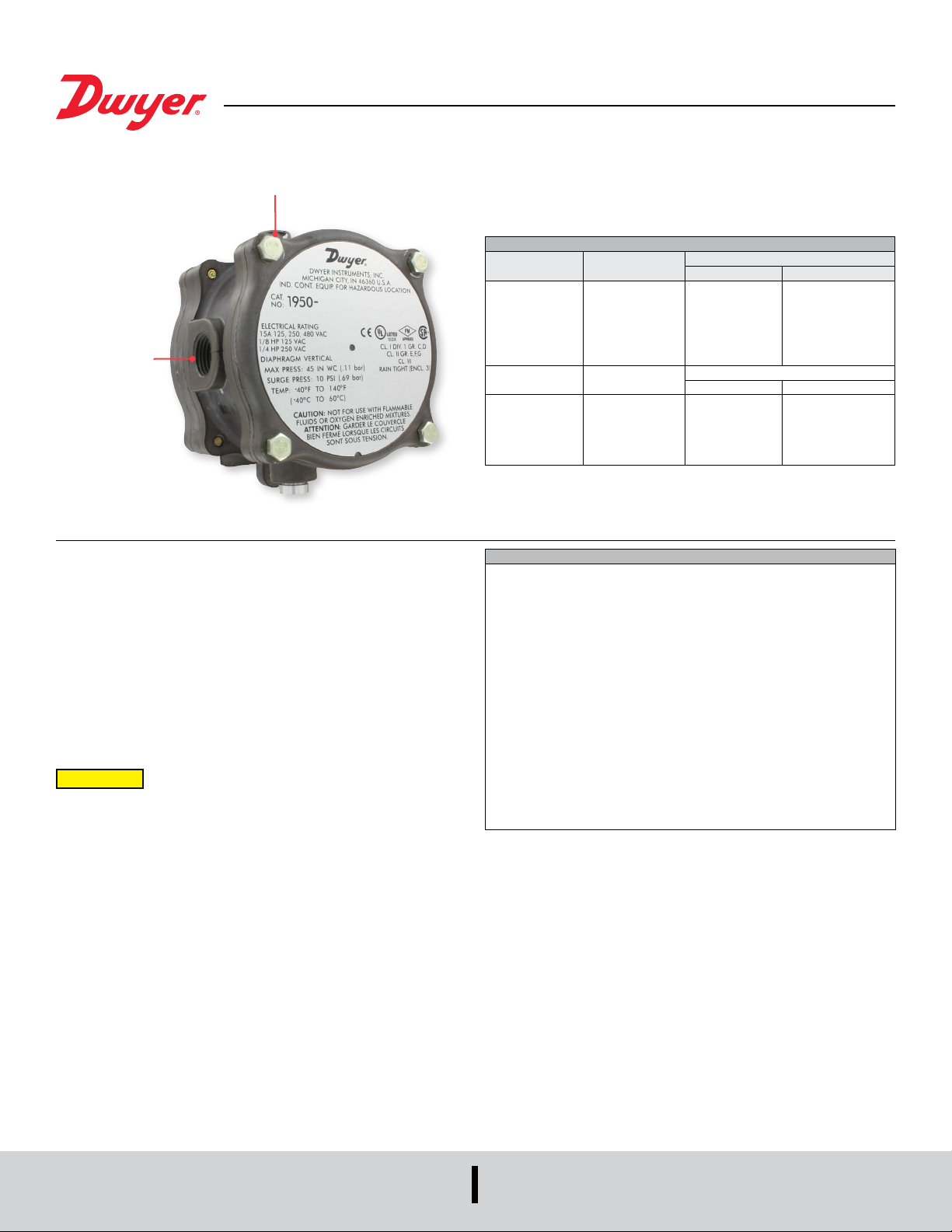
1/2˝ (12.7) female
NPT Electrical
Conduit
Connection
Series 1950 Explosion-Proof Differential Pressure Switches
Specications - Installation and Operating Instructions
Set point
adjustment screw
UL and CSA Listed, FM Approved For
CL. I GR. C, D - CL. II GR. E, F, G - CL. III
SERIES 1950 SWITCHES OPERATING RANGES AND DEADBANDS
To order specify
Model Number
1950-00-2F
1950-0-2F
1950-1-2F
1950-5-2F
1950-10-2F
1950-20-2F
Model Number
1950P-2-2F
1950P-8-2F
1950P-15-2F
1950P-25-2F
1950P-50-2F
Operating Range
Inches, w.c.
0.07 to 0.15
0.15 to 0.5
0.4 to 1.6
1.4 to 5.5
3.0 to 11.0
4.0 to 20.0
Operating
Range: PSI
0.5 to 2.0
1.5 to 8.0
3.0 to 15.0
4.0 to 25.0
15.0 to 50
Approximate Dead Band
At Min. Set Point At Max. Set Point
0.04
0.10
0.15
0.3
0.4
0.4
Approximate Dead Band
Min. Set Point Max. Set Point
0.3 psi
1.0 psi
0.9 psi
0.7 psi
1.0 psi
Bulletin E-57
0.05
0.15
0.20
0.4
0.5
0.6
0.3 psi
1.0 psi
0.9 psi
0.7 psi
1.5 psi
Series 1950 Explosion-Proof Differential Pressure Switches combine the best
features of the Series 1900 Pressure Switch with an integral explosion-proof and
weather-proof housing. Each unit is UL and CSA listed; FM approved for use in Class I,
Groups C and D; Class II, Groups E, F, and G; and Class III atmospheres (NEMA 7 and
9). They are totally rain-tight for outdoor installations. Twelve models allow setpoints
from .03 to 20 inches w.c. and from .5 to 50 psi (3.4 to 345 kPa). Easy access to the
SPDT switch for electrical hook-up is provided by removing the top plate of the threepart aluminum housing. Adjustment to the set point of the switch can be made without
disassembling the housing. The unit is very compact, about half the weight and bulk of
equivalent conventional explosion-proof switches.
Easy access to the SPDT switch for electrical hook-up is provided by removing the top
plate of the three-part aluminum housing. Adjustment to the set point of the switch can
be made without disassembling the housing. The unit is very compact, about half the
weight and bulk of equivalent conventional explosion-proof switches.
CAUTION
(including differential pressure applications in such media) is not recommended.
Switch contact arcing can cause an explosion inside the switch housing which, while
contained, may render the switch inoperative. If switch is being used to sense a single
positive pressure relative to atmosphere, run a line from the low pressure port to a
non-hazardous area free of combustible gases. This may increase response time on
-0 and -00 models.
Note: The last number-letter combination in the model number identies the switch’s
electrical rating (number) and diaphragm material (letter). The 2F combination is
standard as described in the physical data above. In case of special models, a number
1 rating is the same as 2; a number 3 or 4 rating is 10A 125, 250, 480 VAC; 1/8 H.P.
125 VAC; 1/4 H.P. 250 VAC; a number 5 or 6 rating is 1A 125 VAC. Letter B indicates
a Buna-N diaphragm; N = Neoprene; S = Silicone; and V = Viton
For use only with air or compatible gases. Use of the Model 1950
switch with explosive media connected to the Low pressure port
®
.
SPECIFICATIONS
Service: Air and non-combustible, compatible gases.
Wetted Materials: Consult factory.
Temperature Limits: -40 to 140°F (-40 to 60°C); 0 to 140°F (-17.8 to 60°C) for
1950P-8, 15, 25, and 50. -30 to 130°F (-34.4 to 54.4°C) for 1950-02.
Pressure Limits: Continuous: 1950’s - 45˝ w.c. (0.11 bar); 1950P’s - 35 psi (2.41
bar); 1950P-50 only - 70 psi (4.83 bar). Surge: 1950’s - 10 psi (0.69 bar), 1950P’s -
50 psi (3.45 bar), 1950P-50 only - 90 psi (6.21 bar).
Enclosure Rating: IP54, NEMA 3, 7 and 9.
Switch Type: Single-pole double-throw (SPDT).
Electrical Rating: 15 A @, 125, 250, 480 VAC, 60 Hz. Resistive 1/8 HP @ 125
VAC, 1/4 HP @ 250 VAC, 60 Hz.
Electrical Connections: 3 screw type, common, normally open and normally
closed.
Process Connections: 1/8˝ female NPT.
Mounting Orientation: Diaphragm in vertical position. Consult factory for other
position orientations.
Set Point Adjustment: Screw type on top of housing.
Weight: 3.25 Ib (1.5 kg); 1950-02 model, 4.4 lb (2 kg).
Compliance: CE, UL, CSA, FM.
RESPONSE TIME: Because of restrictive effect of ame arrestors, switch response
time may be as much as 10-25 seconds where applied pressures are near set point.
DWYER INSTRUMENTS, LLC
P.O. BOX 373 • MICHIGAN CITY, INDIANA 46360, U.S.A.
Phone: 219-879-8000
Fax: 219-872-9057
www.dwyer-inst.com
e-mail: [email protected]
Page 2

EXTERNAL
HOLES EQUALL
1/8 FEMALE NPT
3-1/2 [88.90]
GROUND
[2] Ø17/64 [6.75] MOUNTING
Y SPACED ON
A 4-7/8 [123.83] B.C.
RANGE
ADJUSTMENT
SCREW
5-7/16 [138.13]
VENT DRAIN
PLUG
LOW PRESSURE
CONNECTION
CAPTIVE SCREW
1-23/32 [43.64]
1-15/32 [37.30]
3/8 [9.53]
27/32 [21.43]
27/32 [21.43]
3/8 [9.53]
NOTE: 1950-02: 7-3/4˝ [196.9] DIA.
X 4-11/32˝ [110.3] DEPTH. FOR
COMPLETE DIMENSIONS REQUEST
DRAWING 28-700175-00 FROM
OUR CUSTOMER SERVICE
DEPARTMENT
1/8 FEMALE NPT HIGH
PRESSURE CONNECTION
1/2 FEMALE NPT
ELECTRICAL CONNECTION
INSTALLATION
1. Select a location free from excess vibration and corrosive atmospheres where
temperatures will be within the limits noted under Specications on reverse. Switch
may be installed outdoors or in areas where the hazard of explosion exists. See
reverse for specic types of hazardous service.
2. Mount standard switches with the diaphragm in a vertical plane and with switch
lettering and nameplate in an upright position. Some switches are position sensitive
and may not reset properly unless they are mounted with the diaphragm vertical.
3. Connect switch to source of pressure, vacuum or differential pressure. Metal tubing
with 1/4˝ O.D. is recommended, but any tubing which will not restrict the air ow
can be used. Connect to the two 1/8˝ female NPT pressure ports as noted below:
A. Differential pressures - connect pipes or tubes from source of greater pressure
to high pressure port marked HIGH PRESS, and from source of lower
pressure to low pressure port marked LOW PRESS.
B. Pressure only (above atmospheric pressure) - connect tube from source of
pressure to high pressure port. The low pressure port is left open to
atmosphere.
C. Vacuum only (below atmospheric pressure) - connect tube from source of
vacuum to low pressure port. The high pressure port is left open to
atmosphere.
4. To make electrical connections, remove the three hex head screws from the
cover and after loosening the fourth captive screw, swing the cover aside. Electrical
connections to the standard single pole, double throw snap switch are provided by
means of terminals marked “COM” (common), “NO” (norm open), “NC” (norm
closed). The normally open contacts close and the normally closed contacts open
when pressure increases beyond the set point. Switch loads for standard models
should not exceed the maximum specied current rating of 15 amps resistive.
Switch capabilities decrease with an increase in ambient temperature, load
inductance, or cycling rate. Whenever an application involves one or more of these
factors, the user may nd it desirable to limit the switched current to 10 amps or
less in the interest of prolonging switch life.
ADJUSTMENT: To Change the Set point
1. Remove the plastic cap and turn the slotted Adjust-ment Screw at the top of the
housing clockwise to raise the set point pressure and counterclockwise to lower the
set point. After calibration, replace the plastic cap and re-check the set point.
2. The recommended procedure for calibrating or checking calibration is to use a
“T” assembly with three rubber tubing leads, all as short as possible and the
entire assembly offering minimum ow restriction. Run one lead to the pressure
switch, another to a manometer of known accuracy and appropriate range, and
apply pressure through the third tube. Make nal approach to the set point very
slowly. Note that manometer and pressure switch will have different response times
due to different internal volumes, lengths of tubing, uid drainage, etc. Be certain
the switch is checked in the position it will assume in use, i.e. with diaphragm in a
vertical plane and switch lettering and Dwyer nameplate in an upright position.
3. For highly critical applications check the set point adjustment and if necessary,
reset it as noted in step A.
MAINTENANCE
The moving parts of these switches need no maintenance or lubrication. The only
adjustment is that of the set point. Care should be taken to keep the switch reasonably
clean. Periodically the vent drain plug should be rotated, then returned to its original
position. This will dislodge deposits which could accumulate in applications where
there is excessive condensation within the switch. The Series 1950 Explosion-Proof
Differential Pressure Switch is not eld serviceable and should be returned if repair
is needed (eld repair should not be attempted and may void warranty). Be sure to
include a brief description of the problem plus any relevant application notes. Contact
customer service to receive a return goods authorization number before shipping.
DWYER INSTRUMENTS, LLC
P.O. BOX 373 • MICHIGAN CITY, INDIANA 46360, U.S.A.
Printed in U.S.A. 11/23 FR# 440332-00 Rev. 15©Copyright 2023 Dwyer Instruments, LLC
Phone: 219-879-8000
Fax: 219-872-9057
www.dwyer-inst.com
e-mail: [email protected]
 Loading...