

Page 1
Series 190 Displacer Type Liquid Level Controls
By Dwyer
Specications - Installation and Operating Instructions
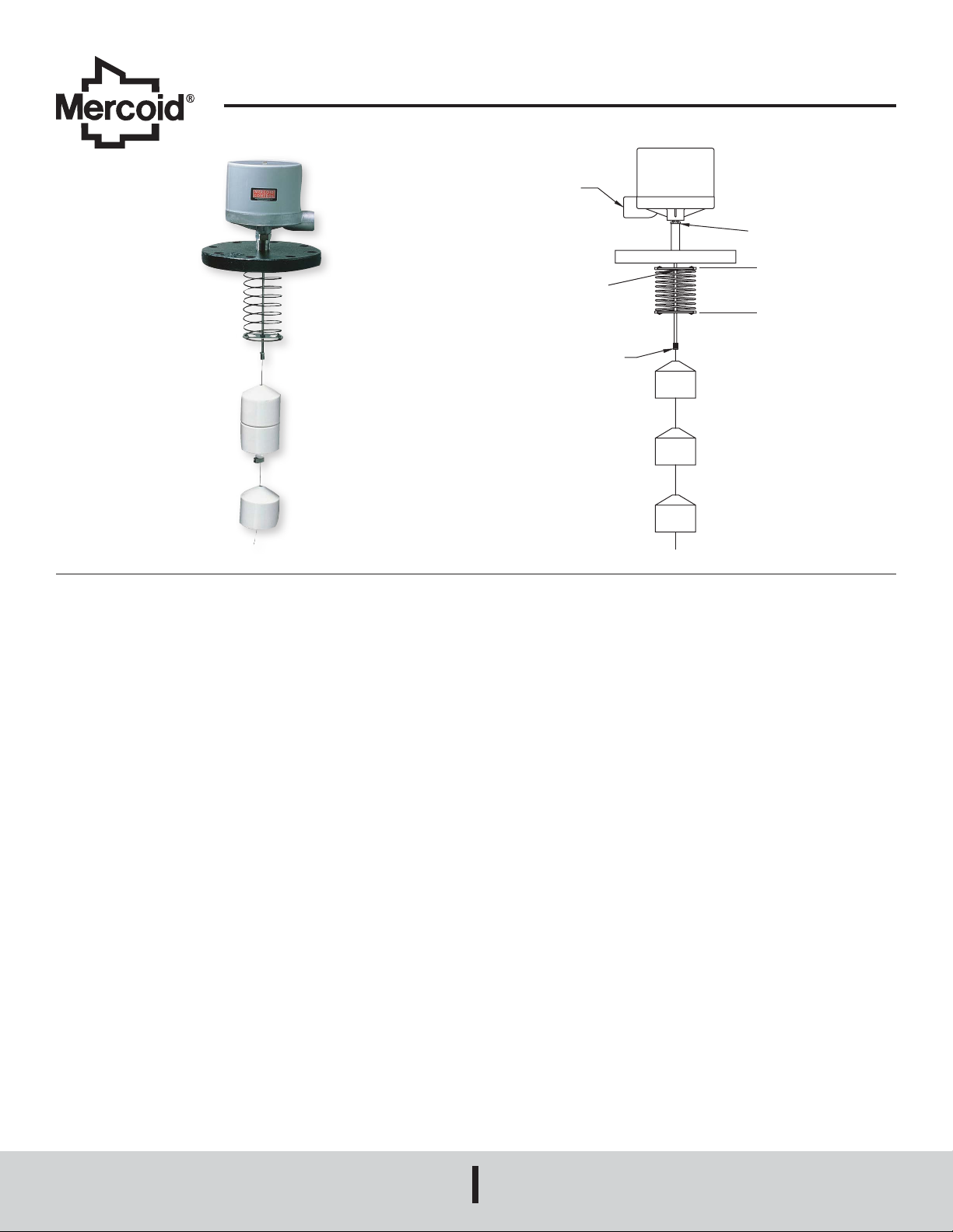
3/4˝ NPT
CONDUIT
CONNECTION
SPRING CLIP
PULL OUT TO RELEASE
ARMATURE ASSEMBLY
THREADED CLAMP
Bulletin O-532
3/4˝ NPT
SPRING ASSEMBLY
(FACTORY SET)
OPERATING CHARACTERISTICS
The displacers are suspended on a cable from the armature of a magnetic head control
with a spring partially supporting their weight. As the displacers become submerged
in a rising liquid, their weight decreases, allowing the spring to move the cable and
armature upward, thereby actuating the mercury switches or snap action switches.
The displacers are secured on the cable by clamps. Operating levels can be adjusted
by loosening the clamps and moving the displacers up or down the cable as required.
The buoyancy produced by the submerging of one displacer is not sufcient to allow
the spring to raise the armature*; a second displacer must be partially submerged
before any operation occurs on a rise. On a drop, however, the cable will not move to
its full down position until the level falls to approximately the mid point of the lowest
displacer. By spacing the displacers and calibrating the spring, adjustable level
operation and various stage operations can be provided.
*Exception - Typer 195-4: Lower stage operates on and off as liquid level move
within length of lower displacer.
Typer A-190 operates on and off as liquid level moves within length of a single
displacer.
Construction - all types. Standard displacers are porcelain (also available of other
materials). Stops 316SS. Cable (10 ft) 316 stainless steel (longer lengths available).
All enclosures equipped with 3/4˝ NPT conduit connection. Terminal block for electrical
connections. Stand ange: 4˝ 125# C1 - other sizes and materials available.
INSTALLATION INSTRUCTIONS
MOUNTING
All types must be mounted with switch mechanism in a level position. Flange must be
positioned so that control is mounted level.
Check for obstructions in tank or vessel - be sure that no rods, projections or other
obstacles interfere with free operations of the displacers.
PROCEDURE FOR INSTALLING CONTROL HEAD AND DISPLACERS
Note: Do not tamper with setting of spring assembly. It has been factory set for the
specic gravity specied on your order.
Disassemble equipment as follows:
a. Remove spring clip located near bottom end of the threaded connection
protruding from control case. Pull out on spring clip which releases armature rod,
and spring assembly.
b. Insert control head thru ange and tighten securely by means of the treaded
connection. Use a wrench only on the hex surface under control base.
c. Reassemble armature rod with spring assembly into bottom opening of the
threaded pipe connection and secure with spring clip. Note: On two stage models
be sure washer is inside tube before inserting spring clip. To facilitate insertion of
washer and spring clip turn control upside down on a rm surface.
d. Attach cable and displacers to armature by means of the threaded clamp
attached to the cable.
e. Insert complete assembly and ange into the tank or vessel and fasten ange.
WIRING
Wire in accordance with local electrical codes or follow equipment manufacturers
instructions.
CAUTION: Do not loosen or move switch mechanisms or control adjustment will be
altered. Do not tamper with switch wires. Position of these wires is essential to proper
operation. Tampering with these wires will void warranty.
No guides are necessary unless excessive turbulence occurs, in which case, a guide
pipe could be used. The inner diameter of the pipe or tube should be at least one half
to one inch larger than the diameter of the displacers and should have a vent above
the high level of he liquid - bottom end to be open.
MERCOID
A DIVISION OF
DWYER INSTRUMENTS, INC.
P.O. BOX 373 • MICHIGAN CITY, INDIANA 46360, U.S.A.
Phone: 219/879-8000
Fax: 219/872-9057
www.dwyer-inst.com
e-mail: [email protected]
Page 2
SINGLE STAGE OPERATION
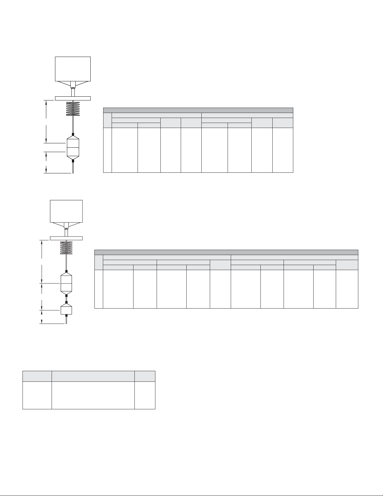
Single stage controls will operate at any specic gravity and temperature listed in
tables with standard factory setting.
Series A190 - Single Stage - Fixed Differentials
A-190
Series A190 - Single Stage - Fixed Differentials
SPGR100°F 200°F
A
C
TB
Series B190 - Single Stage - Adjustable Differentials
A C Min.TB A C Min. TB
Max. Min. Max. Min.
0.5
121.5 [3086]
0.6
122 [3100]
0.7
122 [3100]
0.8
122.5 [3111]
0.9
123 [3124]
1.0
123 [3124]
1.1
123 [3124]
1.2
123 [3124]
7-1/2 [190]
8 [203]
8-1/2 [216]
9 [229]
9 [229]
9 [229]
9 [229]
9-1/2 [241]
1-1/2 [38]
1-1/4 [32]
1-1/8 [29]
1 [25]
7/8 [22]
3/4 [19]
5/8 [16]
3/8 [16]
2-3/4 [70]
2-1/2 [64]
2-3/8 [60]
2-1/4 [57]
2-1/8 [54]
2 [51]
2 [51]
1-7/8 [48]
121 [3073]
121 [3073]
122 [3100]
122 [3100]
122 [3100]
122.5 [3111]
122.5 [3111]
122.5 [3111]
7 [178]
7-1/2 [190]
8 [203]
8 [203]
8-1/2 [216]
8-1/2 [216]
8-1/2 [216]
8-1/2 [216]
1-3/4 [44]
1-1/2 [38]
1-1/4 [32]
1-1/8 [29]
1 [25]
7/8 [22]
3/4 [19]
3/4 [19]
3-1/4 [83]
2-7/8 [73]
2-3/4 [70]
2-1/2 [64]
2-3/8 [60]
2-1/4 [57]
2-1/8 [54]
2-1/8 [54]
B-190
Series B190 - Single Stage - Adjustable Differentials
A
C
TB
SINGLE STAGE CIRCUIT SPECIFICATIONS AND ELEC. RATING
MERCURY SWITCH TYPES
AC or DC
10 amp. 120 volts, 5 amp. 240 volts
Available 440 volts 3 amp. A.C.
Circuit
Arrangement
SP-ST
SP-ST
SP-DT
DP-ST
DP-ST
ENCLOSED METAL CONTACT SNAP-ACTION SWITCHES
12 Amp. 120 volts; 5 Amp. 240 volts AC.
1/2 hp. 120/240 volts AC
D.C. 0.5 Amp. 125 volts; 0.25 Amp. 250 volts
Circuit Response to Liquid Level
Changes
Close on level DROP
Close on level RISE
One circuit CLOSES other circuit OPENS
Close on level DROP
Close on level RISE
SPGR100°F 200°F
A C TB Min. A C TB Min.
Max Min Max Min Max Min Max Min
0.6
116-1/2 [2959]
0.7
117 [2972]
0.8
118 [2997]
0.9
118-1/2 [3010]
1.0
119 [3023]
1.1
119 [3023]
1.2
120 [3048]
Minimum differential (c) can be reduced, approximately 1˝ by removing the cable clamp from between the displacers and turning the lower
displacer so the at side is up. If a narrower differential is needed, use a Type A190 control.
6-1/2 [165]
7-1/2 [191]
8 [203]
8-1/2 [216]
9 [229]
9-1/2 [241]
9-1/2 [241]
Spec
NO.
No. 4820
No. 4821
No. 4815
No. 4814
No. 4813
114 [2896]
115-1/2 [2934]
115 [2921]
115 [2921]
114-1/2 [2908]
114-1/2 [2908]
114-1/2 [2908]
6-3/4 [171]
6 [152]
5-1/2 [140]
5 [127]
4-5/8 [117]
4-3/8 [111]
4 [102]
2-1/2 [64]
2-3/8 [60]
2-1/4 [57]
2-1/8 [54]
2 [51]
1-7/8 [48]
1-3/4 [44]
-
-
118 [2997]
118-1/2 [3010]
119 [3023]
119 [3023]
119-1/2 [3035]
-
-
8 [203]
8-1/2 [216]
8-1/2 [216]
9 [229]
9 [229]
-
-
115 [2921]
114-1/2 [2908]
114-1/2 [2908]
114 [2896]
114 [2896]
-
-
4-3/4 [121]
4-3/8 [111]
4-1/8 [105]
3-7/8 [98]
3-3/4 [95]
-
-
3 [76]
2-7/8 [73]
2-5/8 [67]
2-1/2 [64]
2-3/8 [60]
CIRCUITS
SINGLE STAGE
Spec. No. 7810 (1) SP-DT Switch
Spec. No 7806 (2) SP-DT Switches
Page 3
TWO STAGE OPERATION
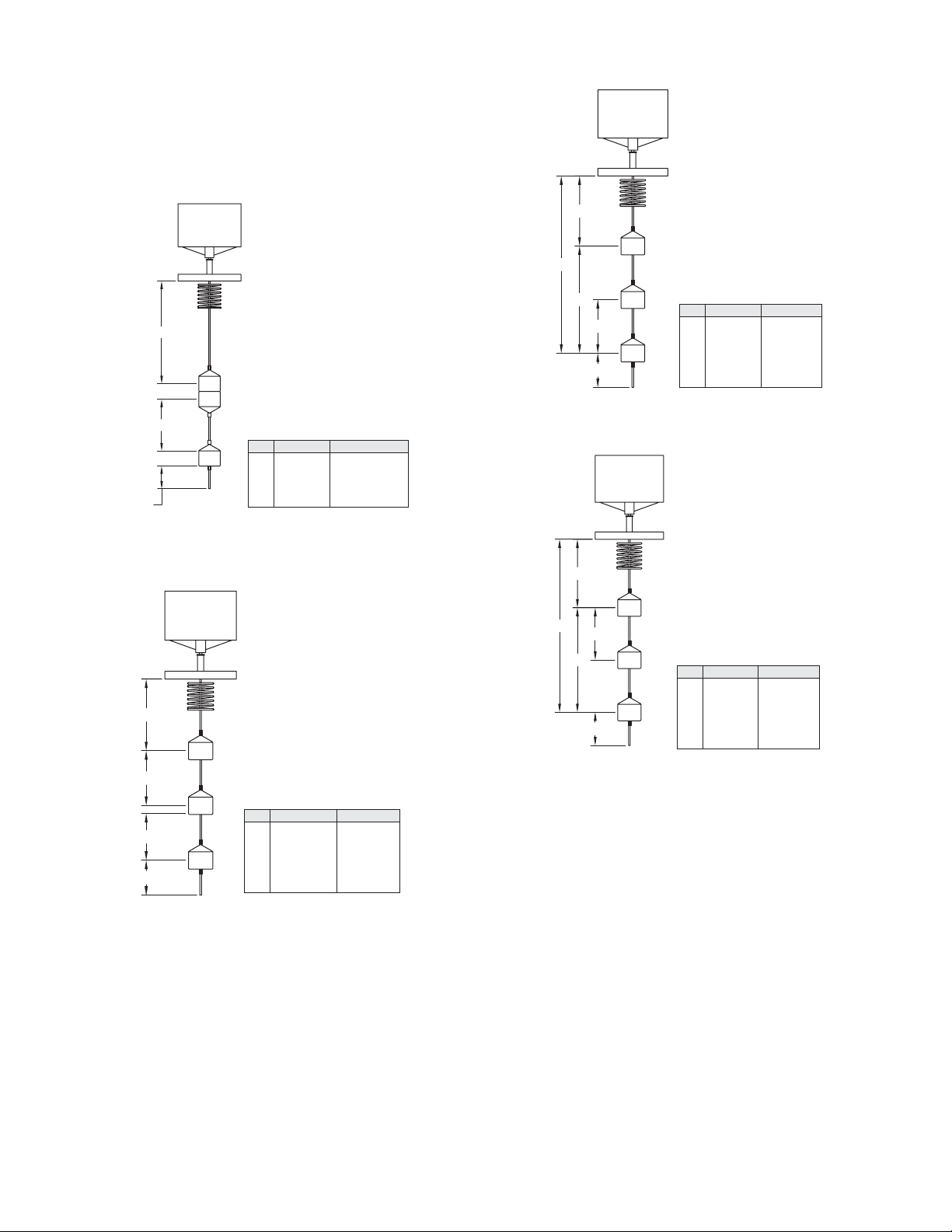
All two stage types are factory set for a given specic gravity and temperature for each
application.
Series 195-7 - Two Stage - Adjustable Differential Each Stage
Common trip point at LOW level
Series 195-4 - Two Stage - Fixed Differentials Adjustable Spread Between
Stages
Minimum Specic Gravity 0-9 - Maximum Temperature 200°
On specic gravities below .95 control is not recommended where temperatures vary
appreciably.
195-4
A
C
D
C
TB
Series 195-6 - Two Stage - Adjustable Differential Each Stage
High trip point for lower stage common with low trip point for upper stage
Min. Max.
A
9˝ [229]
C
3/4˝ [19]
D
3-1/2˝ [89]
TB
1-1/2˝ [38]
119˝ [2997]
Fixed
113-1/2˝ [2882]
-
195-7
A
B
C1
C2
TB
Series 195-8 - Two Stage - Adjustable Differential Each Stage
Common trip point at HIGH level
195-8
Min. Max.
A
9˝ [229]
B
16˝ [406]
C1
7˝ [76]
C2
3-1/2˝ [89]
TB
2˝ [51]
118˝ [2997]
125˝ [3175]
116˝ [2946]
112˝ [2845]
-
Minimum Specic Gravity 0.5 - Maximum Temperature 200°
195-6
A
C
Min. Max.
A
D
TB
B
C1
C2
TB
9˝ [229]
15-1/2˝ [394]
3˝ [76]
3-1/2˝ [89]
3˝ [51]
118˝ [2997]
125˝ [3175]
113˝ [2870]
113˝ [2870]
-
A
B
C2
C1
TB
Min. Max.
A
9˝ [229]
B
16˝ [406]
C1
7˝ [76]
C2
3-1/2˝ [89]
TB
2˝ [51]
118˝ [2997]
125˝ [3175]
116˝ [2946]
112˝ [2845]
-
Page 4

Specic gravity should not vary more than ±.1 from factory setting. Temperature
should not vary more than ±50°F from factory setting.
Note: Single stage displacer controls will tolerate much wider uctuations of specic
gravity and temperature as indicated in tables.
TWO STAGE CIRCUIT SPECIFICATIONS AND ELEC. RATING
Mercury Switch types
AC or DC
10 Amp. 120 volts
5 Amp. 240 volts
4 Amp. - No. 4810
2 Amp. - No 4810
Circuit
Arrangement
SP-ST
SP-ST
SP-DT
SP-DT
DP-ST
DP-ST
ENCLOSED METAL CONTACT SNAP-ACTION SWITCHES
12 Amp. 120 volts; 5 Amp. 240 volts AC.
1/2 hp. 120/240 volts AC
D.C. 0.5 Amp. 125 volts; 0.25 Amp. 250 volts
CIRCUITS
Spec. No. 7806 (2 SP-DT each stage)
Spec. No. 7810 (SP-DT each stage)
Circuit Response to
Liquid Level Changes
Open on level DROP
Open on level RISE
One circuit OPENS as
other circuit CLOSES
One circuit OPENS as
other circuit CLOSES
Close on level RISE
Open on level RISE
Lower
Stage
No. 4820
No. 4821
No. 4810
No. 4815
No. 4814
No. 4813
Upper
Stage
-21
-26
-10
-15
-13
-14
MERCOID
A DIVISION OF
DWYER INSTRUMENTS, INC.
P.O. BOX 373 • MICHIGAN CITY, INDIANA 46360, U.S.A.
Printed in U.S.A. 4/18 FR# 441865-00 Rev. 1©Copyright 2018 Dwyer Instruments, Inc.
Phone: 219/879-8000
Fax: 219/872-9057
www.dwyer-inst.com
e-mail: [email protected]
 Loading...