

Page 1
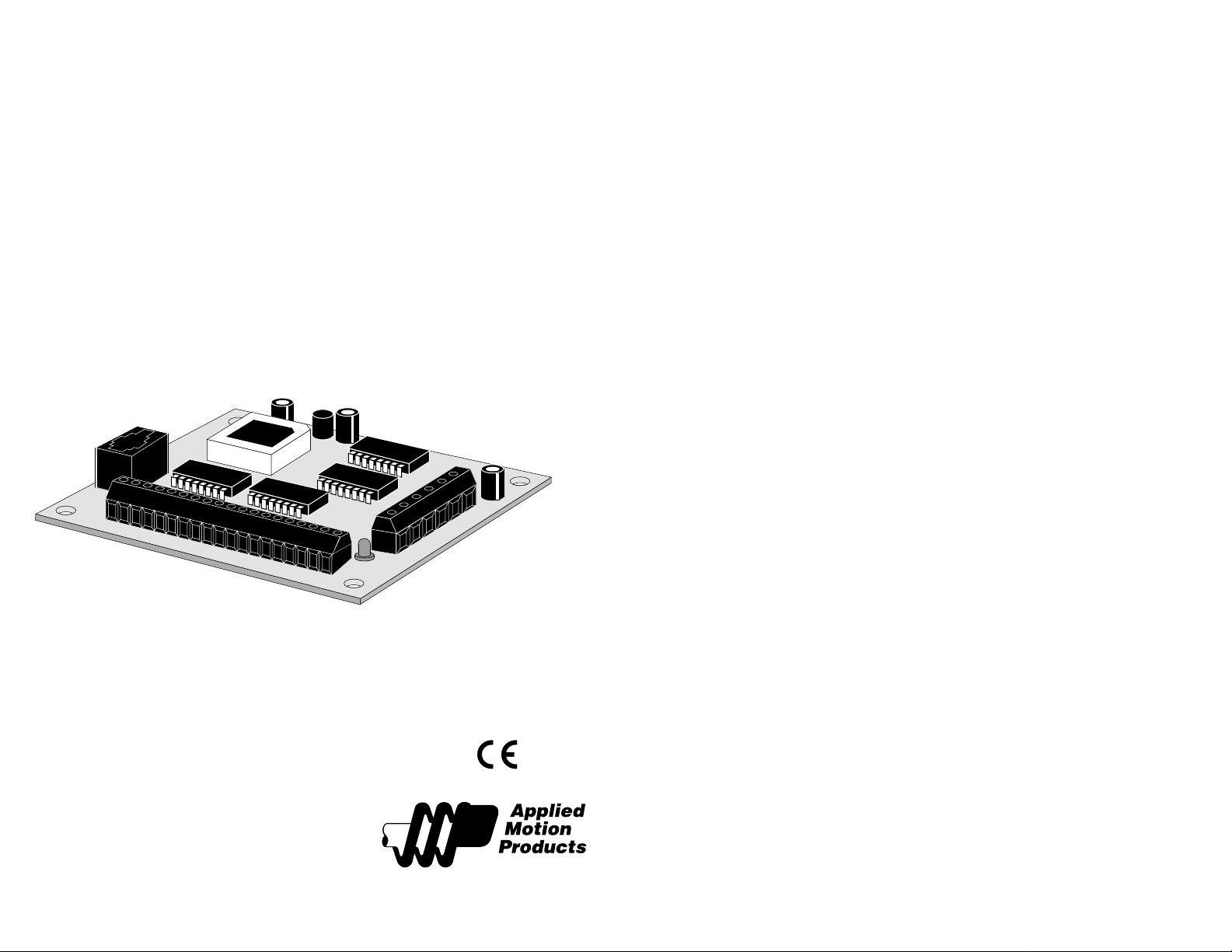
Hardware Manual
1240i
Programmable Step Motor Driver
motors • drives • controls
-2-
Page 2

T able of Contents
Introduction --------------------------------------------------------------------- 4
Features-------------------------------------------------------------------------- 4
Block Diagram------------------------------------------------------------------- 4
Getting Started ------------------------------------------------------------------ 5
Introduction
Thank you for selecting an Applied Motion Products motor control. We hope our
dedication to performance, quality and economy will make your motion control
project successful. If there’s anything we can do to improve our products or help
you use them better, please call or fax. We’d like to hear from you. Our phone
number is (800) 525-1609 or you can reach us by fax at (831) 761-6544.
Connecting the Power Supply --------------------------------------------------- 6
Choosing a Power Supply ------------------------------------------------------- 7
Connecting the Motor ----------------------------------------------------------- 8
Connecting to the PC------------------------------------------------------------ 9
Jogging------------------------------------------------------------------------- 10
Limit Switches ----------------------------------------------------------------- 10
Wiring a Mechanical Limit Switch --------------------------------------------- 11
Wiring a Limit Sensor ---------------------------------------------------------- 11
Wiring Inputs------------------------------------------------------------------- 12
Wiring Outputs ----------------------------------------------------------------- 14
Microstepping ------------------------------------------------------------------ 15
Mounting the Drive------------------------------------------------------------- 16
Mounting the Optional MMI --------------------------------------------------- 17
Recommended Motors---------------------------------------------------------- 19
Mechanical Outline------------------------------------------------------------- 20
Technical Specifications -------------------------------------------------------- 21
Mechanical Outline - Optional MMI ------------------------------------------- 22
Features
• Precise pulse width modulation switching amplifiers providing up to 1.2 amps per
phase and microstepping to 50,800 steps per revolution.
• Accepts 12 - 42 VDC power supply.
• Powerful, flexible, easy to use indexer.
• Connects by a simple cable to your PC for programming (cable included).
• Microsoft WindowsTM-based software for easy setup and programming
• Eight inputs for interacting with the user and other equipment.
• Three outputs for coordinating external equipment.
• External trigger I/O is optically isolated, 5-24V, sinking or sourcing signals.
PC/ MMI port is RS-232.
• 3.0 x 4.0 x 0.65 inch overall dimensions.
• Optional man machine interface (MMI) allows operator to enter distances,
speeds, cycle counts and more.
• CE Compliant
Block Diagram
12 - 42 VDC
INPUT1
INPUT2
INPUT3
INPUT4
CW JOG/IN5
CCW JOG/IN6
CW LIMIT
CCW LIMIT
Optical
Isoation
Optical
Isolation
Internal
Power
Supply
Microstepping
Sequencer
Si
™
Indexer
eeprom
MOSFET
3 State
PWM
Power
Amplifier
motor phase A
motor phase B
-3-
to PC/MMI
RS232
-4-
Optical
Isolation
OUT1
OUT2
OUT3
Page 3
Getting Started
To use your 1240i motor control, you will need the following :
4 a power supply (see page7 for help choosing one).
4 a compatible step motor (see page 19 for recommended motors).
4 a small flat blade screwdriver for tightening the connectors - an Applied Motion
Products screwdriver suitable for this purpose is included with your drive.
4 a personal computer running Windows 3.1, 95, 98 or NT with a 9 pin serial port
(486 or better with 8 MB ram recommended)
4 the Si ProgrammerTM software that came with your 1240i
4 the programming cable that came with your 1240i
4 Si ProgrammerTM software manual - on the CD that came with your 1240i
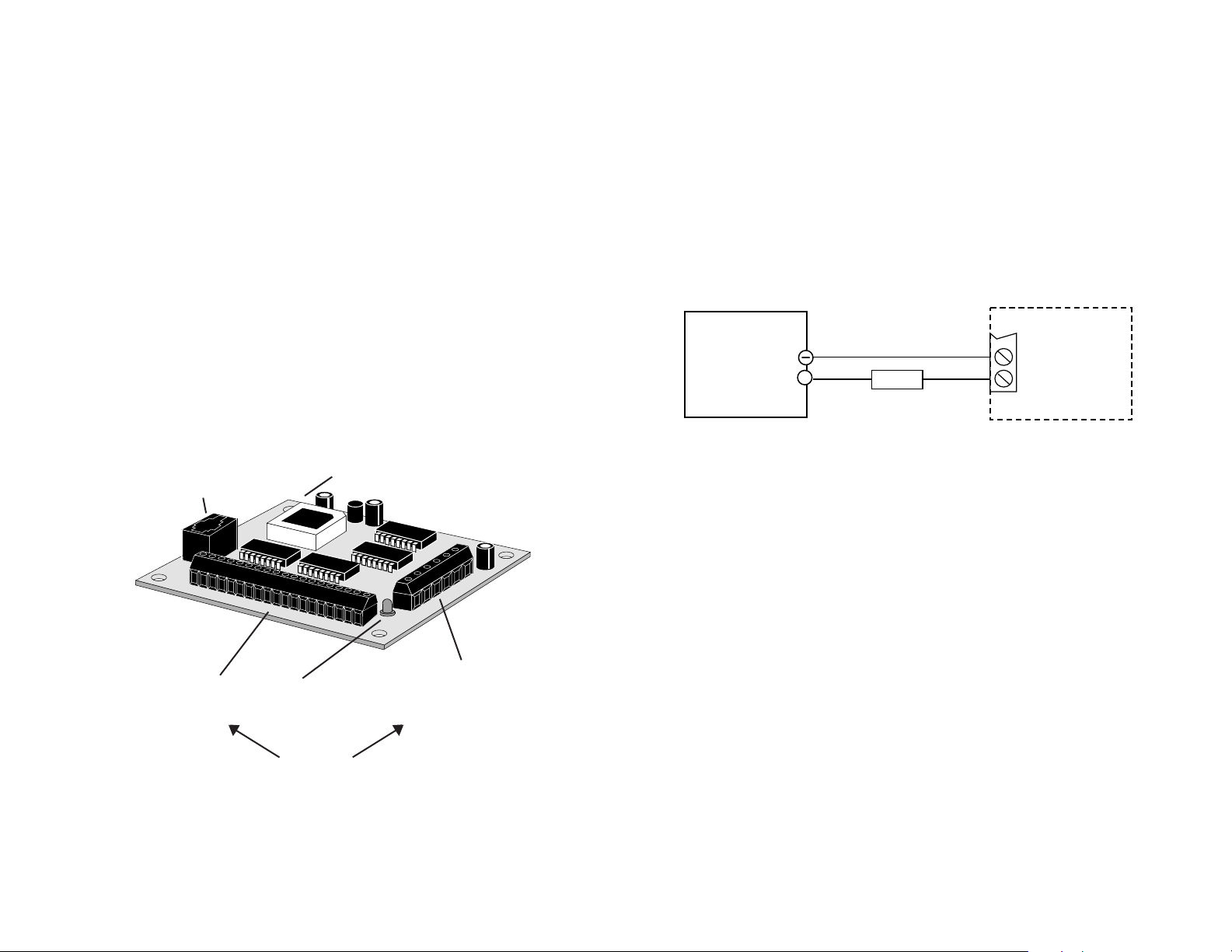
The sketch below shows where to find the important connection and adjustment
points. Please examine it now.
All Mating connectors included.
Connecting the Power Supply
If you need information about choosing a power supply, please read
Power Supply
on the next page.
If your power supply does not have a fuse on the output or some kind of short
circuit current limiting feature, you need to put a 1 amp fast acting fuse between the
drive and the power supply. Install the fuse on the + power supply lead.
Connect the motor power supply as shown below. Use no smaller than 18 gauge
wire. Be careful not to reverse the wires. Reverse connection may destroy your
driver, void your warranty and generally wreck your day.
DC Power
Supply
+
-
V +
Choosing a
1240i
12 - 42 V
1A fuse
pc/mmi
connector
i/o connector
inputs 1,2,3,4
jog cw
jog ccw
cw limit
ccw limit
out 1,2,3
mounting hole (1 of 4)
power LED
* Always use the blue & white
Applied Motion screwdriver
with these connectors.
Larger screwdrivers may remove
the plastic dimples that prevent
the screws from falling out.
-5-
power/motor
connector
DC power supply
motor
-6-
Page 4
Choosing a Power Supply
Please follow the recommendations below for choosing a power supply:
Voltage
Chopper drives like the 1240i work by switching the voltage to the motor terminals
on and off while monitoring current to achieve a precise level of phase current. To
do this efficiently and silently, you’ll want to have a power supply with
rating at least five times that of the motor
. Depending on how fast you want to run
the motor, you may need even more voltage than that. If you choose an unregulated
power supply, do not exceed 28 volts. This is because unregulated supplies are
rated at full load current. At lesser loads, like when the motor’s not moving, the
actual voltage can be up to 1.4 times the rated voltage. For smooth, quiet operation, a lower voltage is better.
Current
The maximum supply current you could ever need is the sum of the two phase
currents. However, you will generally need a lot less than that, depending on the
motor type, voltage, speed, and load conditions. That’s because the 1240i uses
switching amplifiers, converting a high voltage and low current into lower voltage
and higher current. The more the power supply voltage exceeds the motor voltage,
the less current you’ll need from the power supply. A motor running from a 24 volt
supply can be expected to draw only half the supply current that it would with a 12
volt supply.
We recommend the following selection procedure:
1) If you plan to use only a few drives, get a power supply with at least twice the
rated phase current of the motor.
2) If you are designing for mass production and must minimize cost, get one power
supply with more than twice the rated current of the motor. Install the motor in the
application and monitor the current coming out of the power supply and into the
drive at various motor loads. This will tell you how much current you really need so
you can design in a lower cost power supply. If you plan to use a regulated power
supply you may encounter a problem with current fold back. When you first power
up your drive, the full current of both motor phases will be drawn for a few milliseconds while the stator field is being established. After that the amplifiers start
chopping and much less current is drawn from the power supply. If your power
supply thinks this initial surge is a short circuit it may “fold back” to a lower
voltage. Because of that, unregulated power supplies are better. They are also less
expensive.
a voltage
Connecting the Motor
Never connect or disconnect the motor to the driver when the
power is on.
Insulate unused motor leads separately, and then secure.
Never connect motor leads to ground or to a power supply.
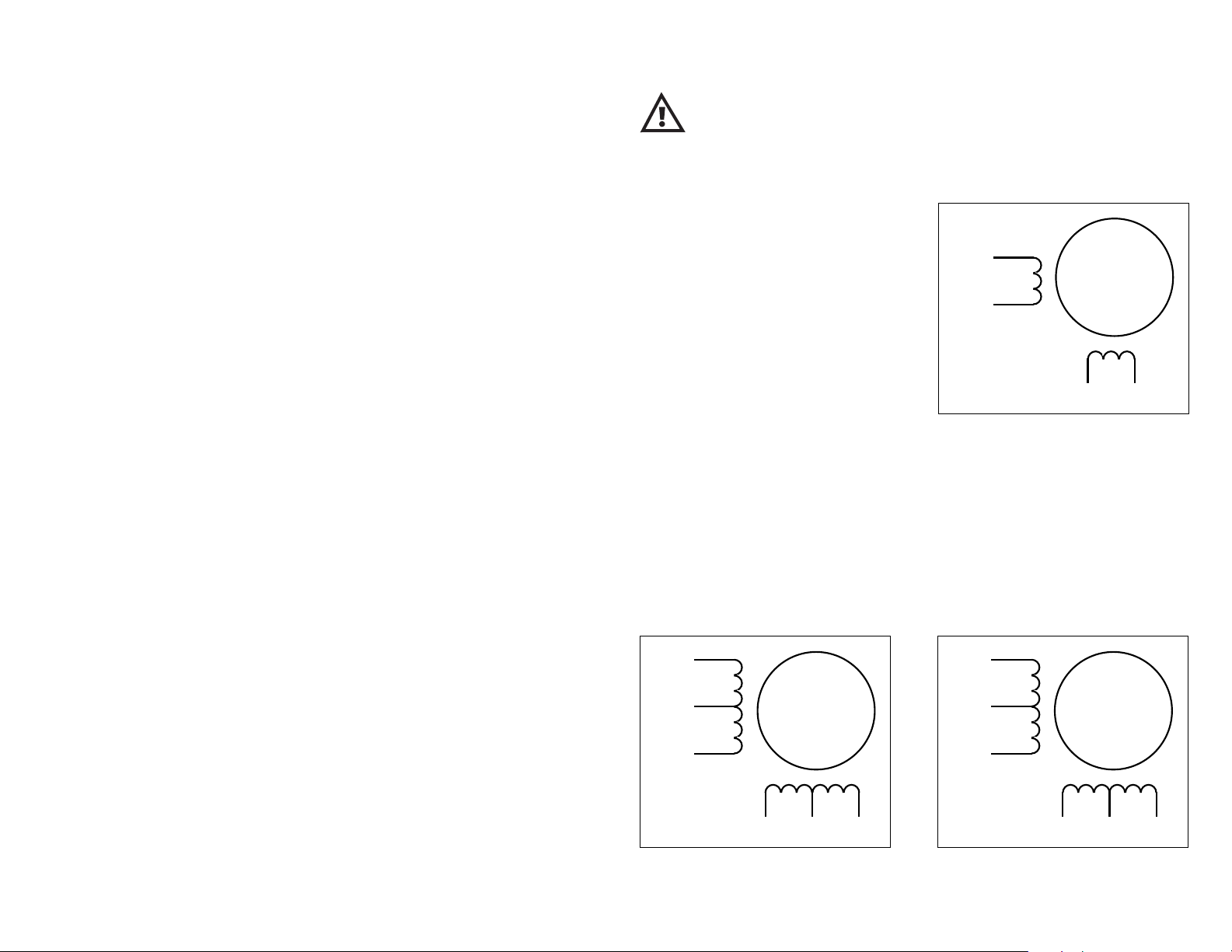
You must now decide how to connect your
motor to the drive.
A+
Red
4
lead
Four lead motors can only be connected
one way. Please follow the sketch at the
A–
Blue
right.
Yellow
4 Leads
Six lead motors can be connected in series or center tap. In series mode, motors
produce more torque at low speeds, but cannot run as fast as in the center tap
configuration. In series operation, the motor should be operated at 30% less than
the rated current to prevent overheating. Wiring diagrams for both connection
methods are shown below.
motor
White
B+ B–
Note: NC means not connected to anything.
Grn/Wht
A–
White
NC
Green
A+
Red
B–
6 Leads Series Connected 6 Leads Center Tap Connected
lead
motor
Black
NC
6
Red/
Wht
B+
A–
A+
NC
Grn/Wht
White
Green
Red
lead
motor
Black
6
Red/
Wht
B+B–
NC
-7-
-8-
Page 5
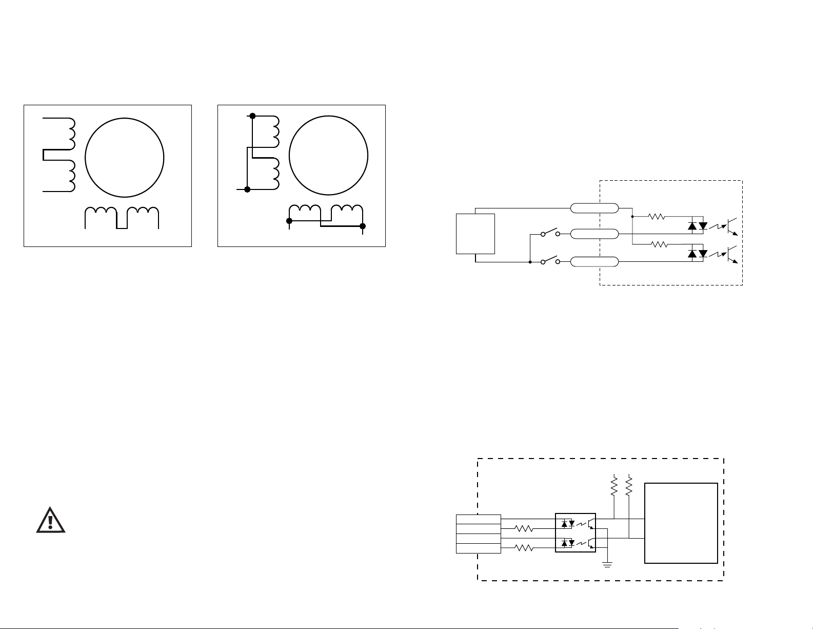
Eight lead motors can also be connected in two ways: series and parallel. As
with six lead motors, series operation gives you more torque at low speeds and less
torque at high speeds. In series operation, the motor should be operated at 30%
less than the rated current to prevent overheating. The wiring diagrams for eight
lead motors are shown below.
Orange
A+
Org/Wht
8
Blk/Wht
lead
Blk/Wht
A–
Black
Red
8 Leads Series Connected 8 Leads Parallel Connected
motor
Red/
Wht
B+ B–
Yel/
Wht
A–
Yellow
A+
Org/
Wht
Orange
Black
Red
B+
Yel/
Wht
8
lead
motor
Red/Wht
Yel
low
B–
Connecting to the PC
•Locate your computer within 6 feet of the 1240i.
•Your 1240i was shipped with a black adapter plug. It has a telephone style jack at
one end and a larger 9 pin connector at the other. Plug the large end into the COM1
serial port of your PC. Secure the adapter with the screws on the sides. If the
COM1 port on your PC is already used by something else, you may use the COM2
port for the 1240i. On some PCs, COM2 will have a 25 pin connector that does not
fit the black adapter plug. If this is the case, and you must use COM2, you may
have to purchase a 25 to 9 pin serial adapter at your local computer store.
•Your 1240i was also shipped with a 7 foot telephone line cord. Plug one end into
the adapter we just attached to your PC, and the other end into the PC/MMI jack on
your 1240i.
Jogging
Two of the 1240i input terminals are provided for jogging the motor. The inputs are
labeled “JOG CW” and “JOG CCW”. Activating one of the inputs commands the
drive to move the motor at a pre-designated speed until the contact is opened. A
relay or mechanical switch can be used to activate the jog inputs. 5-24 volt circuitry can be used. The schematic diagram of the input circuit is shown below.
If you’re using a switch or relay, wire one end to the JOG input and the other to the
power supply negative (-) terminal. Then connect the COM input to the power
supply positive (+) terminal.
inside 1240i
2200
2200
+
5-24
VDC
SUPPLY
-
COM
JOG CW
JOG CCW
Limit Switches
The 1240i has two limit switch inputs, LIMIT CW and LIMIT CCW. By connecting
switches or sensors that are triggered by the motion of the motor or load, you can
force the 1240i to operate within certain limits. This is useful if a program error
could cause damage to your system by traveling too far.
The limit inputs are optically isolated. This allows you to choose a voltage for your
limit circuits of 5 to 24 volts DC. This also allows you to have long wires on limit
sensors that may be far from the 1240i with less risk of intoducing noise to the
1240i. The schematic diagram of the limit switch input circuit is shown below.
inside 1240i
+5V +5V
10K
Never connect the 1240i to a telephone circuit. It uses the
same connectors and cords as telephones and modems, but the
voltages are not compatible.
Programming Note: Always apply power to the 1240i after the SiTM Programmer
software is running on your PC.
-9-
CW LIMIT+
CW LIMIT–
CCW LIMIT+
CCW LIMIT–
2200
3
4
1
2
1240i
Controller
Chip
-10-
Page 6
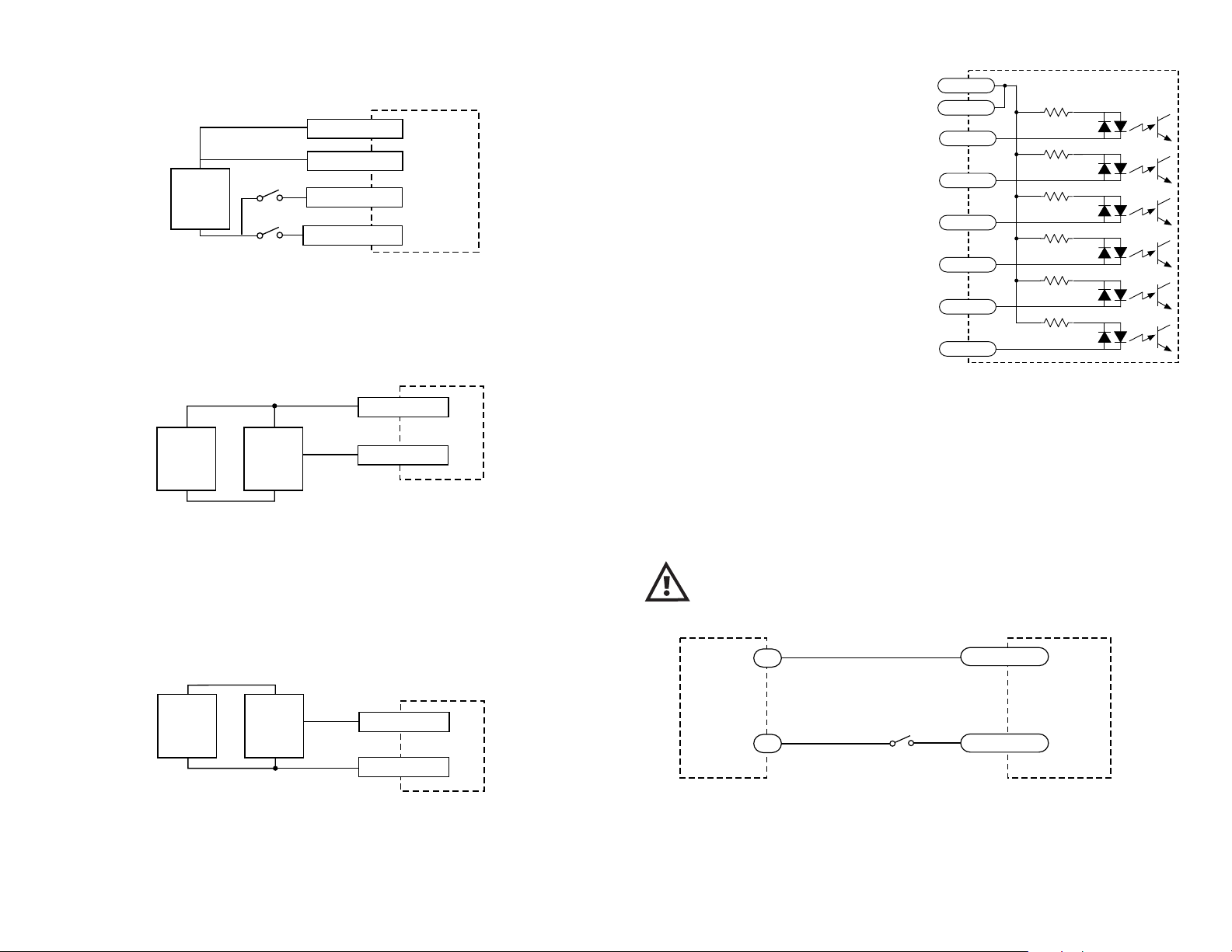
Wiring a Mechanical Limit Switch
You can use normally open or normally closed limit switches. Either way, wire
them as shown here.
CW LIMIT+
+
5-24
VDC
SUPPLY
-
CCW LIMIT+
1240i
CW LIMIT-
CCW LIMIT-
Wiring a Limit Sensor
Some systems use active limit sensors that produce a voltage output rather than a
switch or relay closure. These devices must be wired differently than switches.
If your sensor has an open collector output or a sinking output, wire it like this:
Wiring Inputs
The 1240i input circuits can be used with
sourcing or sinking signals, 5 to 24 volts.
This allows connection to TTL circuits,
PLCs, relays and mechanical switches.
Because the input circuits are isolated, they
require a source of power. If you are
connecting to a TTL circuit or to a PLC, you
should be able to get power from the PLC or
TTL power supply. If you are using relays or
mechanical switches, you will need a 5-24 V
power supply. This also applies if you are
connecting the 1240i inputs to another Si
product from Applied Motion, like the Si-1
and Si-100 indexers or the 3540i, Si3540,
Si5580, 7080i and Si4500 indexer-drives.
COM
COM
IN1
IN2
IN3
IN4
JOG CW
JOG CCW
inside 1240i
2200
2200
2200
2200
2200
2200
CW LIMIT+
+
DC
Power
Supply
–
+
Limit
Sensor
–
output
CW LIMIT-
1240i
Wiring for Sinking or Open Collector Output
If the sensor output goes low at the limit, select the option “closed”. If the output
is open, or high voltage, choose “open”.
Other sensors have sourcing outputs. That means that current can flow out of the
sensor output, but not into it. In that case, wire the sensor this way:
+
DC
Power
Supply
–
+
Proximity
Sensor
–
output
LIMIT+
1240i
LIMIT-
Wiring for Sourcing Output
If the sensor output goes high at the limit, choose the program option “closed”. if
the output is low at the limit, select “open”.
Note: If current is flowing into or out of an 1240i input, the logic state of that input
is low. If no current is flowing, or the input is not connected, the logic state is
high.
The diagrams on the following pages show how to connect 1240i inputs to various
devices.
The maximum voltage that can be applied to an input terminal is
24 volts DC. Never apply AC voltage to an input terminal.
+
COM
5-24
VDC
Power
Supply
Use normally open momentary switch to trigger 1240i using Wait Input instruction.
Use single throw switch for parameter selection using If Input instruction.
-
Use normally open momentary switch for jogging.
switch or relay
(closed=logic low)
Connecting an Input to a Switch or RelayConnecting an Input to a Switch or Relay
Connecting an Input to a Switch or Relay
Connecting an Input to a Switch or RelayConnecting an Input to a Switch or Relay
1240i
IN
-11-
-12-
Page 7
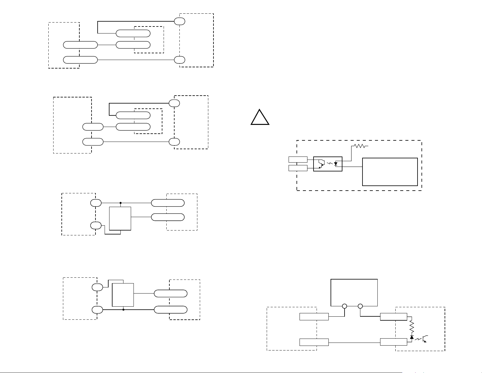
+
IN/JOG COM
1240i
5-24
VDC
MOTION+
MOTION–
SI-1 indexer
Connecting an Input to the Si-1 Motion Output
(Set Si-1 motion signal to “in position”. Si-1 will trigger 1240i at end of each move).
OUT+
or Si-100
Si5580, Si4500
OUT–
3540i, Si3540, 7080i,
Connecting a 3540i, Si3540, Si5580, 7080i or Si4500
(When output closes, 1240i input goes low).
IN
COM
IN
1240i
+
-
Power
Supply
-
5-24
VDC
Power
Supply
Wiring Outputs
Before we discuss the output conditions, we need to talk about the circuitry. All
three 1240i outputs are optically isolated. That means that there is no electrical
connection between the indexer-drive and the output terminals. The signal is
transmitted to the output as light. What you “see” is a transistor (NPN type) that
closes, or conducts current, when the output is “low”. When the output is high, the
transistor is open.
Note: At power-up, the 1240i sets all three programmable outputs high (open
circuit).
The maximum voltage between any pair of + and - output
terminals is 24 volts DC. Never connect AC voltages to the
!
1240i output terminals. Maximum current is 100 mA per output.
+5V
330
OUT1+
OUT1–
inside 1240i
1240i
Controller Chip
5-24
5-24
VDC
VDC
Power
Power
Supply
Supply
Connecting an NPN Type Proximity Sensor to a 1240i input
(When prox sensor activates, 1240i input goes low).
5-24
5-24
VDC
VDC
Power
Power
Supply
Supply
Connecting a PNP Type Proximity Sensor to a 1240i input
(When prox sensor activates, 1240i input goes low).
+
+
+
+
output
output
NPN
NPN
Proximity
Proximity
Sensor
-
-
+
+
Sensor
–
–
+
+
output
output
PNP
PNP
Proximity
Proximity
Sensor
Sensor
–
–
-
-
COM
COM
IN
IN
IN
IN
COM
COM
1240i
1240i
-13-
Schematic Diagram of 1240i Output Circuit
Since there is no electrical connection to the 1240i, you must provide the source of
current and voltage, typically from a power supply. You must also limit the current
to less than 100 mA so that the output transistor is not damaged. You would
normally use a resistor for this, but some loads (such as PLC inputs) limit the
current automatically.
The diagram below shows how to connect an 1240i output to an optically isolated
PLC input.
5-24 VDC
Power Supply
+–
OUTPUT+
COMMON
PLC
1240i
OUTPUT-
-14-
INPUT
Page 8
Microstepping
Most step motor drives offer a choice between full step and half step resolutions.
In full step mode, both motor phases are used all the time. Half stepping divides
each step into two smaller steps by alternating between both phases on and one
phase on.
Microstepping drives like the 1240i precisely control the amount of current in each
phase at each step position as a means of electronically subdividing the steps even
further. The 1240i offers a choice of 13 step resolutions. The highest setting
divides each full step into 254 microsteps, providing 50,800 steps per revolution
when using a 1.8° motor.
In addition to providing precise positioning and smooth motion, microstep drives
can be used for motion conversion between different units. The 25,400 step/rev
setting is provided as a means of converting motion from metric to english (there
are 25.4 mm in an inch). Other settings provide step angles that are decimal
degrees (36,000 steps/rev makes the motor take 0.01° steps). Some settings are
used with lead screws. When the drive is set to 2000 steps/rev and used with a 0.2
pitch lead screw, you get 0.0001 inches/step.
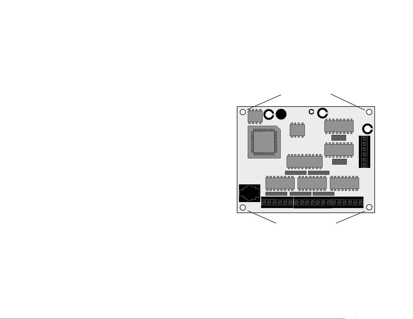
Mounting the Drive.
The 1240i has four 0.156 inch diameter holes in the circuit board for mounting.
Always use standoffs or spacers to support the 1240i: a 1240i with power connected
will be damaged if you set it on a conductive surface without supports. The
standoffs or spacers can be up to 0.25 inch in outer diameter. You can use #4 or #6
screws to fasten the 1240i.
0.156 inch Diameter
mounting holes
The microstep resolution of the 1240i is set by the Si ProgrammerTM software.
-15-
0.156 inch Diameter
mounting holes
-16-
Page 9

Mounting the Optional MMI
There are two ways to mount the MMI in your application. No matter which method
you choose, you’ll need to connect the MMI to your 1240i with the programming
cable. You will not, however, need the adapter plug. The MMI has the same
telephone style connector as the 1240i.
Depending on how you mount the MMI and cable in your application, you may find
that it is difficult to remove the cable from the back of the MMI. If this is the case,
and you need to reprogram the 1240i, you can use any telephone line cord as a
programming cable. They are available at most supermarkets and discount stores.
Please be careful not to lose the adapter plug that connects the telephone cord to
the COM port of your PC. The adapter is a custom made part and is only available
from Applied Motion.
Flush Mounting
When you remove the MMI from the shipping carton, you will notice that it has two
parts. The first is a fairly thin section that contains the keypad, display and some
circuit boards. The other part is thicker and contains the telephone jack and a cable
that connects to the keypad assembly.
When you flush mount the MMI in a
panel, only the thin section will stick out
from your panel - the large portion mounts
MMI
(rear section)
MMI
(front section
and gasket)
behind your panel. You’ll need to cut a
precise section from your panel. There is
a cardboard template in the MMI’s
shipping box for this purpose.
If you want the MMI to be dust proof and
watertight, you must place the black
123
456
789
.0
SPACE BKSP ENTER
➝
➝
YES NO
➝
➝
panel
rubber gasket between the thin part of the
MMI and your panel. Assemble the two
halves using the eight small screws
provided.
Surface Mounting
An easier way to mount the MMI is to bolt the two halves together ahead of time,
using the eight small screws. If you want the MMI to be dust proof and watertight,
put the black rubber gasket between the two halves before screwing them together.
Then cut a hole in your panel for the cable
that runs between the MMI and the 1240i.
The hole must be at least 5/8” in diameter
gasket
(included)
sealant (not included)
panel
for the connector to fit thorugh. You will
also need two holes that line up with the
big mounting holes in the MMI. The
mechanical outline on page 22 shows the
location of the big mounting holes.
When you mount the MMI to your panel,
you will need to use some kind of sealant
to keep dust and liquid out. Silicone or
123
456
789
.0
SPACE BKSP ENTER
➝
➝
YES NO
➝
➝
MMI
latex caulking is okay, or you can make
your own gasket from a sheet of compliant
material like rubber or RTV.
-17-
-18-
Page 10
Recommended Motors
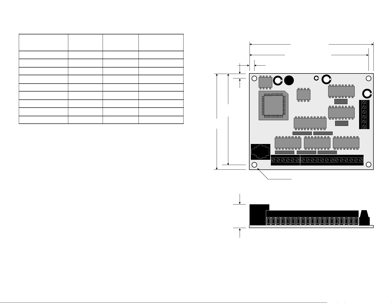
Mechanical Outline
Motor
Number
HT11-012 1.0
HT11-013 1.0
5014-842 1.0
HT17-068
HT17-072
HT17-076
HT23-393 1.2
HT23-396 1.2
HT23-399
Winding
Connection
series
series
series
parallel
parallel
parallel
parallel
parallel
1.2
parallel
Max T orque
oz-in
7
10
19
22
1.2
32
1.1
52
1.1
45
115
170
Current Setting
Amps/phase
4.00 IN.
3.85 IN.
0.15 IN.
0.15 IN.
2.85 IN.
3.00 IN.
4 HOLES, 0.156 DIA.
-19-
0.65 IN.
-20-
Page 11
T echnical Specifications
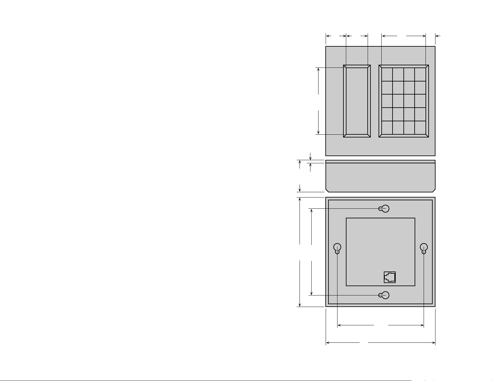
Mechanical Outline - Optional MMI
Amplifiers
Power Supply
Inputs
Outputs
Microstepping
Motion Update
Physical
Dual H-bridge, 3 state, pulse width modulated (PWM) switching at 25
kHz. 0.2 - 1.2 amps/phase output current, software selectable. 48
watts maximum output power. Automatic idle current reduction
(software programmable) reduces current to motor when idle. Minimum motor inductance is 0.8 mH.
Accepts 12 - 42 VDC power supply. 1.2 amps typical max. load.
5 - 24 VDC, optically isolated. 2200 ohms internal resistance. Can be
configured for sinking (NPN) or sourcing (PNP) signals.
Optically isolated. 5-24 VDC, 100 mA max.
13 software selectable resolutions. Steps per revolution with 1.8°
motor: 2000, 5000, 10000, 12800, 18000, 20000, 21600, 25000,
25400, 25600, 36000, 50000, 50800. Waveform: pure sine.
12800 Hz.
Constructed on 0.063 inch thick printed circuit board. Four mounting
holes, 0.156 inch diameter. Overall size : 3.00 x 4.00 x 0.65 inches.
0.15 lb. 0 to 50°C ambient operating temperature. See page 20 for
detailed drawing.
1.38
0.13
2.988
0.960
0.963
1.975
➝
➝
➝
➝
123
YES NO
789
456
0.425
SPACE BKSP ENTER
.0
Connectors
Agency
Approvals
European style screw terminal blocks. Power Supply and Motor: 6
position. Wire size: AWG 16 - 28. Signal input/output: 19 position.
Wire size: AWG 16 - 28.
CE compliant to EN55011A, EN50082-1(1997)
-21-
4.90
3.875
CENTERED
3.875
CENTERED
4.90
-22-
Page 12

Notes
a.r. 1240iweb.p65 4/24/2000
-23-
Applied Motion Products, Inc.
404 Westridge Drive Watsonville, CA 95076
T el (831) 761-6555 (800) 525-1609 Fax (831)-761-6544
http://www.applied-motion.com
Copyright 2000
 Loading...