

Page 1

Page 1 of 87
OMC-900IP
OMC-900IP
OMC-900IP
OMC-900IP BMEGA(F)-(WP)
BMEGA(F)-(WP)
BMEGA(F)-(WP)
BMEGA(F)-(WP) Series
Series
Series
Series
Indoor
Indoor
Indoor
Indoor H.264
H.264
H.264
H.264 Megapixel
Megapixel
Megapixel
Megapixel
IP
IP
IP
IP Box
Box
Box
Box Camera
Camera
Camera
Camera
User
User
User
User Manual
Manual
Manual
Manual
For
For
For
For following
following
following
following models:
models:
models:
models:
OMC-935IPBMEGA
OMC-935IPBMEGA
OMC-935IPBMEGA
OMC-935IPBMEGA :
:
:
: Indoor
Indoor
Indoor
Indoor IP
IP
IP
IP Box
Box
Box
Box Camera
Camera
Camera
Camera ,
,
,
, two
two
two
two way
way
way
way audio
audio
audio
audio
OMC-935IPBMEGAF
OMC-935IPBMEGAF
OMC-935IPBMEGAF
OMC-935IPBMEGAF :
:
:
: Indoor
Indoor
Indoor
Indoor IP
IP
IP
IP Box
Box
Box
Box Camera
Camera
Camera
Camera ,two
,two
,two
,two way
way
way
way audio,with
audio,with
audio,with
audio,with SD
SD
SD
SD card
card
card
card
OMC-935IPBMEGA-P
OMC-935IPBMEGA-P
OMC-935IPBMEGA-P
OMC-935IPBMEGA-P :
:
:
: Indoor
Indoor
Indoor
Indoor PoE
PoE
PoE
PoE IP
IP
IP
IP Box
Box
Box
Box Camera
Camera
Camera
Camera ,
,
,
, two
two
two
two way
way
way
way audio
audio
audio
audio
OMC-935IPBMEGAF-W
OMC-935IPBMEGAF-W
OMC-935IPBMEGAF-W
OMC-935IPBMEGAF-W :
:
:
: In
In
In
In door
door
door
door Wifi
Wifi
Wifi
Wifi IP
IP
IP
IP camera,
camera,
camera,
camera, two
two
two
two way
way
way
way audio,
audio,
audio,
audio, with
with
with
with SD
SD
SD
SD card
card
card
card
Page 2

Page 2 of 87
Contents
Copyright Declaration . . . . . . . . . . . . . . . . . . . . . . . . . . . . . . . . . . . . . . . . . . . . . . . . . . . . . . . . . . . . . . . . . . . . . . . . . . . . . . . . . . . . . . . . . . . . . . . . . . . . . . . . . . . . . . 5
Omcon Software License Agreement . . . . . . . . . . . . . . . . . . . . . . . . . . . . . . . . . . . . . . . . . . . . . . . . . . . . . . . . . . . . . . . . . . . . . . . . . . . . . . . . . . . . 5
1 Before you this product . . . . . . . . . . . . . . . . . . . . . . . . . . . . . . . . . . . . . . . . . . . . . . . . . . . . . . . . . . . . . . . . . . . . . . . . . . . . . . . . . . . . . . . . . . . . . . . . . . . . . . . . . . 6
2 Package Content . . . . . . . . . . . . . . . . . . . . . . . . . . . . . . . . . . . . . . . . . . . . . . . . . . . . . . . . . . . . . . . . . . . . . . . . . . . . . . . . . . . . . . . . . . . . . . . . . . . . . . . . . . . . . . . . . . . 7
3 Physical characteristic . . . . . . . . . . . . . . . . . . . . . . . . . . . . . . . . . . . . . . . . . . . . . . . . . . . . . . . . . . . . . . . . . . . . . . . . . . . . . . . . . . . . . . . . . . . . . . . . . . . . . . . . . . . 7
4 Installation . . . . . . . . . . . . . . . . . . . . . . . . . . . . . . . . . . . . . . . . . . . . . . . . . . . . . . . . . . . . . . . . . . . . . . . . . . . . . . . . . . . . . . . . . . . . . . . . . . . . . . . . . . . . . . . . . . . . . . . . . . . . . . . . 8
4.1 Hardware Installation . . . . . . . . . . . . . . . . . . . . . . . . . . . . . . . . . . . . . . . . . . . . . . . . . . . . . . . . . . . . . . . . . . . . . . . . . . . . . . . . . . . . . . . . . . . . . . . . . . . 8
4.1.1 Connect the Ethernet . . . . . . . . . . . . . . . . . . . . . . . . . . . . . . . . . . . . . . . . . . . . . . . . . . . . . . . . . . . . . . . . . . . . . . . . . . . . . . . . . . . . . . . . 8
4.1.2 Connect the power . . . . . . . . . . . . . . . . . . . . . . . . . . . . . . . . . . . . . . . . . . . . . . . . . . . . . . . . . . . . . . . . . . . . . . . . . . . . . . . . . . . . . . . . . . . 8
4.1.3 connect the external device . . . . . . . . . . . . . . . . . . . . . . . . . . . . . . . . . . . . . . . . . . . . . . . . . . . . . . . . . . . . . . . . . . . . . . . . . . . . 8
4.1.4 Connect PoE IP Camera through Power Over Ethernet (PoE) . . . . . . . . . . . . . . . . . . . . . 8
4.2 Software Installation . . . . . . . . . . . . . . . . . . . . . . . . . . . . . . . . . . . . . . . . . . . . . . . . . . . . . . . . . . . . . . . . . . . . . . . . . . . . . . . . . . . . . . . . . . . . . . . . . . . . . 9
4.2.1 Using Web Browsers . . . . . . . . . . . . . . . . . . . . . . . . . . . . . . . . . . . . . . . . . . . . . . . . . . . . . . . . . . . . . . . . . . . . . . . . . . . . . . . . . . . . . . . . . . . . 9
4.2.2 CMS Installation . . . . . . . . . . . . . . . . . . . . . . . . . . . . . . . . . . . . . . . . . . . . . . . . . . . . . . . . . . . . . . . . . . . . . . . . . . . . . . . . . . . . . . . . . . . . . . . . 16
4.3 IP Surveillance System Connection . . . . . . . . . . . . . . . . . . . . . . . . . . . . . . . . . . . . . . . . . . . . . . . . . . . . . . . . . . . . . . . . . . . . . . . . . . 20
5 IP camera configuration . . . . . . . . . . . . . . . . . . . . . . . . . . . . . . . . . . . . . . . . . . . . . . . . . . . . . . . . . . . . . . . . . . . . . . . . . . . . . . . . . . . . . . . . . . . . . . . . . . . . . . 21
5.1 video and audio settings (General, OSD display, Audio Setting) . . . . . . . . . . . . . . . . . . . . . . . . 22
5.1.1 Video setting . . . . . . . . . . . . . . . . . . . . . . . . . . . . . . . . . . . . . . . . . . . . . . . . . . . . . . . . . . . . . . . . . . . . . . . . . . . . . . . . . . . . . . . . . . . . . . . . . . . . . 22
Advanced image setting skill . . . . . . . . . . . . . . . . . . . . . . . . . . . . . . . . . . . . . . . . . . . . . . . . . . . . . . . . . . . . . . . . . . . . . . . . . . . . . . . . . . . 23
5.1.2 Image setting . . . . . . . . . . . . . . . . . . . . . . . . . . . . . . . . . . . . . . . . . . . . . . . . . . . . . . . . . . . . . . . . . . . . . . . . . . . . . . . . . . . . . . . . . . . . . . . . . . . . 25
5.1.3 Video Flip and Mirror . . . . . . . . . . . . . . . . . . . . . . . . . . . . . . . . . . . . . . . . . . . . . . . . . . . . . . . . . . . . . . . . . . . . . . . . . . . . . . . . . . . . . . . . 26
5.1.4 Audio setting . . . . . . . . . . . . . . . . . . . . . . . . . . . . . . . . . . . . . . . . . . . . . . . . . . . . . . . . . . . . . . . . . . . . . . . . . . . . . . . . . . . . . . . . . . . . . . . . . . . . . 26
5.2 OSD/MASK setting . . . . . . . . . . . . . . . . . . . . . . . . . . . . . . . . . . . . . . . . . . . . . . . . . . . . . . . . . . . . . . . . . . . . . . . . . . . . . . . . . . . . . . . . . . . . . . . . . . . . . . 26
5.3 network settings (General, DHCP,PPPoE,DDNS, FTP, E-mail, Wifi, 3G) . . . . . . . . . . . . . . . . . . 27
5.3.1 General setting . . . . . . . . . . . . . . . . . . . . . . . . . . . . . . . . . . . . . . . . . . . . . . . . . . . . . . . . . . . . . . . . . . . . . . . . . . . . . . . . . . . . . . . . . . . . . . . . . 27
5.3.2 PPPOE . . . . . . . . . . . . . . . . . . . . . . . . . . . . . . . . . . . . . . . . . . . . . . . . . . . . . . . . . . . . . . . . . . . . . . . . . . . . . . . . . . . . . . . . . . . . . . . . . . . . . . . . . . . . . . . . 29
5.3.3 DDNS . . . . . . . . . . . . . . . . . . . . . . . . . . . . . . . . . . . . . . . . . . . . . . . . . . . . . . . . . . . . . . . . . . . . . . . . . . . . . . . . . . . . . . . . . . . . . . . . . . . . . . . . . . . . . . . . . . 29
5.3.4 E-Mail Setting . . . . . . . . . . . . . . . . . . . . . . . . . . . . . . . . . . . . . . . . . . . . . . . . . . . . . . . . . . . . . . . . . . . . . . . . . . . . . . . . . . . . . . . . . . . . . . . . . . . . . 30
5.3.5 FTP setting . . . . . . . . . . . . . . . . . . . . . . . . . . . . . . . . . . . . . . . . . . . . . . . . . . . . . . . . . . . . . . . . . . . . . . . . . . . . . . . . . . . . . . . . . . . . . . . . . . . . . . . . . . 30
5.3.5 WIFI setting (Only for WIFI IP Camera models) . . . . . . . . . . . . . . . . . . . . . . . . . . . . . . . . . . . . . . . . . . . . . . 31
5.3.6 3G setting (Only for 3G IP Camera models) . . . . . . . . . . . . . . . . . . . . . . . . . . . . . . . . . . . . . . . . . . . . . . . . . 33
5.4 PTZ setting . . . . . . . . . . . . . . . . . . . . . . . . . . . . . . . . . . . . . . . . . . . . . . . . . . . . . . . . . . . . . . . . . . . . . . . . . . . . . . . . . . . . . . . . . . . . . . . . . . . . . . . . . . . . . . . . . . . . 36
5.5 System (version, time configuration, system update, user) . . . . . . . . . . . . . . . . . . . . . . . . . . . . . . . . . . . 37
5.5.1 Firmware upgrade, restore, reboot . . . . . . . . . . . . . . . . . . . . . . . . . . . . . . . . . . . . . . . . . . . . . . . . . . . . . . . . . . . . . . . . 37
5.5.2 Time setting . . . . . . . . . . . . . . . . . . . . . . . . . . . . . . . . . . . . . . . . . . . . . . . . . . . . . . . . . . . . . . . . . . . . . . . . . . . . . . . . . . . . . . . . . . . . . . . . . . . . . . . 38
5.5.3 Device information . . . . . . . . . . . . . . . . . . . . . . . . . . . . . . . . . . . . . . . . . . . . . . . . . . . . . . . . . . . . . . . . . . . . . . . . . . . . . . . . . . . . . . . . . . . 39
5.5.4 user management . . . . . . . . . . . . . . . . . . . . . . . . . . . . . . . . . . . . . . . . . . . . . . . . . . . . . . . . . . . . . . . . . . . . . . . . . . . . . . . . . . . . . . . . . . . 40
5.6 Alarm (sensor alarm, motion detection) . . . . . . . . . . . . . . . . . . . . . . . . . . . . . . . . . . . . . . . . . . . . . . . . . . . . . . . . . . . . . . . . . . 41
5.6.1 sensor alarm . . . . . . . . . . . . . . . . . . . . . . . . . . . . . . . . . . . . . . . . . . . . . . . . . . . . . . . . . . . . . . . . . . . . . . . . . . . . . . . . . . . . . . . . . . . . . . . . . . . . . . 41
5.6.2 motion detection . . . . . . . . . . . . . . . . . . . . . . . . . . . . . . . . . . . . . . . . . . . . . . . . . . . . . . . . . . . . . . . . . . . . . . . . . . . . . . . . . . . . . . . . . . . . . 43
5.7 SD Card Record . . . . . . . . . . . . . . . . . . . . . . . . . . . . . . . . . . . . . . . . . . . . . . . . . . . . . . . . . . . . . . . . . . . . . . . . . . . . . . . . . . . . . . . . . . . . . . . . . . . . . . . . . . 45
Page 3

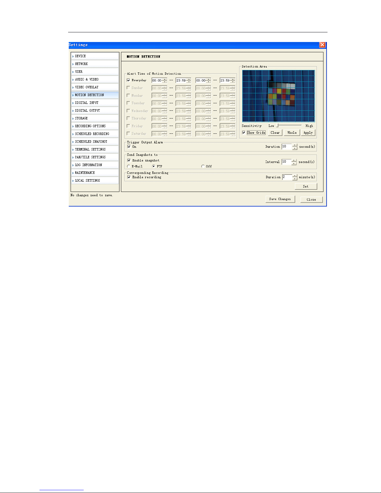
Page 3 of 87
5.7.1 Format SD card . . . . . . . . . . . . . . . . . . . . . . . . . . . . . . . . . . . . . . . . . . . . . . . . . . . . . . . . . . . . . . . . . . . . . . . . . . . . . . . . . . . . . . . . . . . . . . . . . 45
5.7.2 Schedule record on SD card . . . . . . . . . . . . . . . . . . . . . . . . . . . . . . . . . . . . . . . . . . . . . . . . . . . . . . . . . . . . . . . . . . . . . . . . . . 45
5.7.3 Schedule snapshot on SD card . . . . . . . . . . . . . . . . . . . . . . . . . . . . . . . . . . . . . . . . . . . . . . . . . . . . . . . . . . . . . . . . . . . . . . 46
5.7.4 Overwrite setting . . . . . . . . . . . . . . . . . . . . . . . . . . . . . . . . . . . . . . . . . . . . . . . . . . . . . . . . . . . . . . . . . . . . . . . . . . . . . . . . . . . . . . . . . . . . . . 47
5.7.4 Play the record file of SD card . . . . . . . . . . . . . . . . . . . . . . . . . . . . . . . . . . . . . . . . . . . . . . . . . . . . . . . . . . . . . . . . . . . . . . . . 48
5.7.5 Download the record files or snapshots of SD card . . . . . . . . . . . . . . . . . . . . . . . . . . . . . . . . . . . . . 49
5.8 Manual Record over IE . . . . . . . . . . . . . . . . . . . . . . . . . . . . . . . . . . . . . . . . . . . . . . . . . . . . . . . . . . . . . . . . . . . . . . . . . . . . . . . . . . . . . . . . . . . . . . 50
5.8.1 Local record file path . . . . . . . . . . . . . . . . . . . . . . . . . . . . . . . . . . . . . . . . . . . . . . . . . . . . . . . . . . . . . . . . . . . . . . . . . . . . . . . . . . . . . . 50
5.8.2 Play Local record file . . . . . . . . . . . . . . . . . . . . . . . . . . . . . . . . . . . . . . . . . . . . . . . . . . . . . . . . . . . . . . . . . . . . . . . . . . . . . . . . . . . . . . . 50
6 How to use Management software? . . . . . . . . . . . . . . . . . . . . . . . . . . . . . . . . . . . . . . . . . . . . . . . . . . . . . . . . . . . . . . . . . . . . . . . . . . . . . . . . . 52
6.1 System login and logout . . . . . . . . . . . . . . . . . . . . . . . . . . . . . . . . . . . . . . . . . . . . . . . . . . . . . . . . . . . . . . . . . . . . . . . . . . . . . . . . . . . . . . . . . . . . 52
6.1.1 System Login . . . . . . . . . . . . . . . . . . . . . . . . . . . . . . . . . . . . . . . . . . . . . . . . . . . . . . . . . . . . . . . . . . . . . . . . . . . . . . . . . . . . . . . . . . . . . . . . . . . . . 52
6.1.2 Log out system . . . . . . . . . . . . . . . . . . . . . . . . . . . . . . . . . . . . . . . . . . . . . . . . . . . . . . . . . . . . . . . . . . . . . . . . . . . . . . . . . . . . . . . . . . . . . . . . . . 52
6.1.3 Minimize system . . . . . . . . . . . . . . . . . . . . . . . . . . . . . . . . . . . . . . . . . . . . . . . . . . . . . . . . . . . . . . . . . . . . . . . . . . . . . . . . . . . . . . . . . . . . . . . . 52
6.2 System setting . . . . . . . . . . . . . . . . . . . . . . . . . . . . . . . . . . . . . . . . . . . . . . . . . . . . . . . . . . . . . . . . . . . . . . . . . . . . . . . . . . . . . . . . . . . . . . . . . . . . . . . . . . . . . 53
6.2.1 Server management (Add IP camera) . . . . . . . . . . . . . . . . . . . . . . . . . . . . . . . . . . . . . . . . . . . . . . . . . . . . . . . . . 53
6.2.2 User management . . . . . . . . . . . . . . . . . . . . . . . . . . . . . . . . . . . . . . . . . . . . . . . . . . . . . . . . . . . . . . . . . . . . . . . . . . . . . . . . . . . . . . . . . . . 56
6.3 IP Camera live view . . . . . . . . . . . . . . . . . . . . . . . . . . . . . . . . . . . . . . . . . . . . . . . . . . . . . . . . . . . . . . . . . . . . . . . . . . . . . . . . . . . . . . . . . . . . . . . . . . . . 58
6.3.1 Log in and log off IP camera . . . . . . . . . . . . . . . . . . . . . . . . . . . . . . . . . . . . . . . . . . . . . . . . . . . . . . . . . . . . . . . . . . . . . . . . . . 58
6.3.2 Live view IP camera . . . . . . . . . . . . . . . . . . . . . . . . . . . . . . . . . . . . . . . . . . . . . . . . . . . . . . . . . . . . . . . . . . . . . . . . . . . . . . . . . . . . . . . . . 58
6.3.3 Auto log in IP camera and Auto Connect IP camera . . . . . . . . . . . . . . . . . . . . . . . . . . . . . . . . 59
6.4 Remote setup IP Camera . . . . . . . . . . . . . . . . . . . . . . . . . . . . . . . . . . . . . . . . . . . . . . . . . . . . . . . . . . . . . . . . . . . . . . . . . . . . . . . . . . . . . . . . . . 60
6.5 Multi-view IP camera and control . . . . . . . . . . . . . . . . . . . . . . . . . . . . . . . . . . . . . . . . . . . . . . . . . . . . . . . . . . . . . . . . . . . . . . . . . . . . 60
6.5.1 Loop switch . . . . . . . . . . . . . . . . . . . . . . . . . . . . . . . . . . . . . . . . . . . . . . . . . . . . . . . . . . . . . . . . . . . . . . . . . . . . . . . . . . . . . . . . . . . . . . . . . . . . . . . 60
6.5.2 Sound play control and two way audio . . . . . . . . . . . . . . . . . . . . . . . . . . . . . . . . . . . . . . . . . . . . . . . . . . . . . . . 62
6.5.3 PTZ control . . . . . . . . . . . . . . . . . . . . . . . . . . . . . . . . . . . . . . . . . . . . . . . . . . . . . . . . . . . . . . . . . . . . . . . . . . . . . . . . . . . . . . . . . . . . . . . . . . . . . . . . . 63
6.6 Snapshot . . . . . . . . . . . . . . . . . . . . . . . . . . . . . . . . . . . . . . . . . . . . . . . . . . . . . . . . . . . . . . . . . . . . . . . . . . . . . . . . . . . . . . . . . . . . . . . . . . . . . . . . . . . . . . . . . . . . . . 64
6.6.1 How to Snapshot . . . . . . . . . . . . . . . . . . . . . . . . . . . . . . . . . . . . . . . . . . . . . . . . . . . . . . . . . . . . . . . . . . . . . . . . . . . . . . . . . . . . . . . . . . . . . . 64
6.6.2 Search snapshot . . . . . . . . . . . . . . . . . . . . . . . . . . . . . . . . . . . . . . . . . . . . . . . . . . . . . . . . . . . . . . . . . . . . . . . . . . . . . . . . . . . . . . . . . . . . . . . 64
6.7 Record . . . . . . . . . . . . . . . . . . . . . . . . . . . . . . . . . . . . . . . . . . . . . . . . . . . . . . . . . . . . . . . . . . . . . . . . . . . . . . . . . . . . . . . . . . . . . . . . . . . . . . . . . . . . . . . . . . . . . . . . . 65
6.7.1 General setting (Record path, overwrite, record package) . . . . . . . . . . . . . . . . . . . . . . 65
6.7.2 Time Schedule record over Management Software . . . . . . . . . . . . . . . . . . . . . . . . . . . . . . . . . . . 66
6.7.3 Manual record . . . . . . . . . . . . . . . . . . . . . . . . . . . . . . . . . . . . . . . . . . . . . . . . . . . . . . . . . . . . . . . . . . . . . . . . . . . . . . . . . . . . . . . . . . . . . . . . . . 67
6.7.4 Alarm record . . . . . . . . . . . . . . . . . . . . . . . . . . . . . . . . . . . . . . . . . . . . . . . . . . . . . . . . . . . . . . . . . . . . . . . . . . . . . . . . . . . . . . . . . . . . . . . . . . . . . 68
6.8 Playback . . . . . . . . . . . . . . . . . . . . . . . . . . . . . . . . . . . . . . . . . . . . . . . . . . . . . . . . . . . . . . . . . . . . . . . . . . . . . . . . . . . . . . . . . . . . . . . . . . . . . . . . . . . . . . . . . . . . . . 69
6.9 Alarm management . . . . . . . . . . . . . . . . . . . . . . . . . . . . . . . . . . . . . . . . . . . . . . . . . . . . . . . . . . . . . . . . . . . . . . . . . . . . . . . . . . . . . . . . . . . . . . . . . . 71
6.9.1 Sound Alarm . . . . . . . . . . . . . . . . . . . . . . . . . . . . . . . . . . . . . . . . . . . . . . . . . . . . . . . . . . . . . . . . . . . . . . . . . . . . . . . . . . . . . . . . . . . . . . . . . . . . . 71
6.9.2 Pop up alarm message . . . . . . . . . . . . . . . . . . . . . . . . . . . . . . . . . . . . . . . . . . . . . . . . . . . . . . . . . . . . . . . . . . . . . . . . . . . . . . . . . . . 72
6.9.3 Pop up camera video . . . . . . . . . . . . . . . . . . . . . . . . . . . . . . . . . . . . . . . . . . . . . . . . . . . . . . . . . . . . . . . . . . . . . . . . . . . . . . . . . . . . . 73
6.9.4 Electronic Map alarm . . . . . . . . . . . . . . . . . . . . . . . . . . . . . . . . . . . . . . . . . . . . . . . . . . . . . . . . . . . . . . . . . . . . . . . . . . . . . . . . . . . . . . 74
6.9.5 Email notification . . . . . . . . . . . . . . . . . . . . . . . . . . . . . . . . . . . . . . . . . . . . . . . . . . . . . . . . . . . . . . . . . . . . . . . . . . . . . . . . . . . . . . . . . . . 78
6.9.6 History event . . . . . . . . . . . . . . . . . . . . . . . . . . . . . . . . . . . . . . . . . . . . . . . . . . . . . . . . . . . . . . . . . . . . . . . . . . . . . . . . . . . . . . . . . . . . . . . . . . . . . . 81
6.10 Toolbar . . . . . . . . . . . . . . . . . . . . . . . . . . . . . . . . . . . . . . . . . . . . . . . . . . . . . . . . . . . . . . . . . . . . . . . . . . . . . . . . . . . . . . . . . . . . . . . . . . . . . . . . . . . . . . . . . . . . . . . 83
6.10.1 Bottom Toolbar . . . . . . . . . . . . . . . . . . . . . . . . . . . . . . . . . . . . . . . . . . . . . . . . . . . . . . . . . . . . . . . . . . . . . . . . . . . . . . . . . . . . . . . . . . . . . . . 83
Page 4

Page 4 of 87
6.10.2 PTZ Control Toolbar . . . . . . . . . . . . . . . . . . . . . . . . . . . . . . . . . . . . . . . . . . . . . . . . . . . . . . . . . . . . . . . . . . . . . . . . . . . . . . . . . . . . . . . . 85
6.10.3 Alarm Control Toolbar . . . . . . . . . . . . . . . . . . . . . . . . . . . . . . . . . . . . . . . . . . . . . . . . . . . . . . . . . . . . . . . . . . . . . . . . . . . . . . . . . . . . 85
7 Appendix . . . . . . . . . . . . . . . . . . . . . . . . . . . . . . . . . . . . . . . . . . . . . . . . . . . . . . . . . . . . . . . . . . . . . . . . . . . . . . . . . . . . . . . . . . . . . . . . . . . . . . . . . . . . . . . . . . . . . . . . . . . . . . . 85
7.1 FAQ . . . . . . . . . . . . . . . . . . . . . . . . . . . . . . . . . . . . . . . . . . . . . . . . . . . . . . . . . . . . . . . . . . . . . . . . . . . . . . . . . . . . . . . . . . . . . . . . . . . . . . . . . . . . . . . . . . . . . . . . . . . . . . . 85
7.2 factors influencing system capability . . . . . . . . . . . . . . . . . . . . . . . . . . . . . . . . . . . . . . . . . . . . . . . . . . . . . . . . . . . . . . . . . . . . . . . 87
Page 5

Page 5 of 87
Copyright
Copyright
Copyright
Copyright Declaration
Declaration
Declaration
Declaration
This manual is provided by Omcon Technology Co., Ltd (hereinafter referred to as
‘ Omcon ’ ) as the support file for the Omcon Network Video Server, IP camera, etc.
Both the software and this manual are copyrighted and protected by the laws of the
People's R epublic of China.
All rights reserved; no part of this manual may be extracted, modified, copied,
reproduced or transmitted in any form or by any means, electronic or mechanical,
without prior written permission from Omcon. By using this manual, you agree to the
following
Software License Agreement
.
Omcon reserves the right to revise this manual without prior note. Please contact
Omcon for the latest version of this manual.
Omcon has made every effort to ensure the accuracy of this manual but does not
guarantee the absence of errors. Moreover, Omcon assumes no responsibility in
obtaining permission and authorization of any third party patent, copyright or product
involved in relation to the use of this manual.
Note: Windows, Windows NT, Windows 2000, Windows XP and etc. mentioned in this
book are registered trademarks of Microsoft Corporation.
Omcon
Omcon
Omcon
Omcon Software
Software
Software
Software License
License
License
License Agreement
Agreement
Agreement
Agreement
1. Omcon Technology Co., Ltd (hereinafter referred to as ‘ Omcon ’ ) owns the
copyright of ‘ this software and its accessories, relative files and archives ’
(hereinafter referred to as ‘ this product ’ ). No organization, enterprise, agency or
individual may use th is product without our authorization.
2. We authorize those who achieve the following two requirements to use this
product for free:
A. Using this product with hardware products purchased from Omcon through
a legitimate marketing channel;
B. Promising not to transmit the whole or part of this product to any third party
without prior permission from Omcon.
3. Any organization, enterprise, agency or individual, except as otherwise subject to
the second article of this license agreement, must obtain the written permission
from Omcon before using this product.
4. The authorized organizations, enterprises or individuals have no right to transfer the
authorization.
5. The use of this product indicates that you have fully understood and accepted all
terms in this license.
Page 6

Page 6 of 87
1
1
1
1 Before
Before
Before
Before you
you
you
you this
this
this
this product
product
product
product
Safety Notes
All the safety and operation instructions should be read before the unit is used.
Location
Ensure the unit is ventilated to protect from overheating.
Ensure there is a 3cm gap between on both side of the unit
This unit is stored in low humidity and dust free area. Avoid places like damp
basements or dusty hallways
Ensure the unit is not located where it ’ s likely to be subject to mechanical shock
Servicing
Do not attempt to service this unit yourself as opening or removing the covers may
expose you to dangerous voltage or other hazards
Ventilation
Ensure the unit is ventilated to protect from overheating as detailed above.
Warning: To prevent fire or shock hazard, do not expose this unit to rain or moisture.
The lighting flash with arrowhead symbol within an equilateral triangle is indented to
alert the user of this unit there are dangerous voltages within the enclosure tha t may
be of sufficient magnitude to constitute a risk of electric shock.
Lightning Strike
The unit has some in-built protection for lightning strike, however it is recommended
that isolation transformers be fitted to the system in areas where lightening is a
common occurrence.
Page 7
Page 7 of 87
2
2
2
2 Package
Package
Package
Package Content
Content
Content
Content
3
3
3
3 Physical
Physical
Physical
Physical characteristic
characteristic
characteristic
characteristic
Ethernet
Ethernet
Ethernet
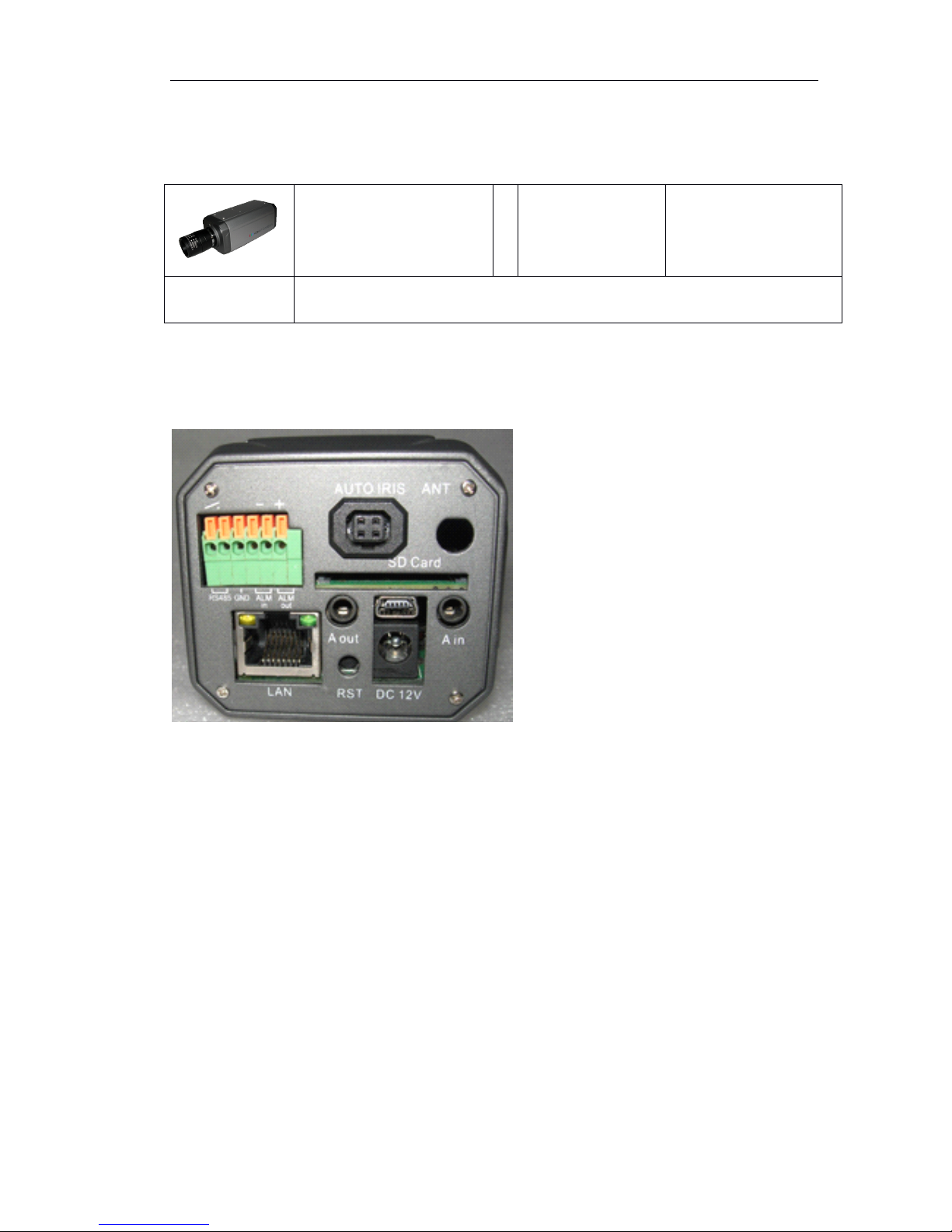
Ethernet : The IP camera connects to the LAN or WAN by a standard RJ45 connector.
IP camera can auto detect the speed of local network segment ( 10Base-T/100Base-TX
Ethernet)
Power
Power
Power
Power : DC 12V input. The LED indicator will light up after IP Camera has successfully
completed the boot process.
A
A
A
A out
out
out
out : audio out,connect the speaker
A
A
A
A in
in
in
in : audio line in, connect the sound amplifier.
SD
SD
SD
SD Card
Card
Card
Card : Insert SD card into slot for local storage. Do not support hot swap the SD card.
R
R
R
R eset
eset
eset
eset : Reset the system or restore the factory settings including the network settings
RS485
RS485
RS485
RS485 : connect pan tilt unit.
GND
GND
GND
GND : ground pin.
ALM
ALM
ALM
ALM in
in
in
in : connect the IR sensor, smoke sensor or other type sensors.
ALM
ALM
ALM
ALM Out
Out
Out
Out : connect the alarm speaker or alarm lamp.
Antenna
Antenna
Antenna
Antenna : OMC-900IPBMEGA-W Series Wireless IP cameras only
Indoor IP Box camera
Software
Compact Disk
User Manual
Tool (DIVX)
CMS
Accessory
12V DC Power adaptor
Antenna (for OMC-900IPBMEGA-W)
Page 8

Page 8 of 87
4
4
4
4 Installation
Installation
Installation
Installation
4.
4.
4.
4. 1
1
1
1 Hardware
Hardware
Hardware
Hardware Installation
Installation
Installation
Installation
4.1.1
4.1.1
4.1.1
4.1.1 Connect
Connect
Connect
Connect the
the
the
the Ethernet
Ethernet
Ethernet
Ethernet
Depending on the user ’ s application, an Ethernet cable is necessary. The Ethernet
cable should meet the specs of UTP Category 5 and not exceed 100 meters in length.
Make sure the Ethernet is firmly connected to a switch hub. The network status LED is
ste ady orange.
4.1.2
4.1.2
4.1.2
4.1.2 Connect
Connect
Connect
Connect the
the
the
the power
power
power
power
Plug in the power adapter.
4.1.3
4.1.3
4.1.3
4.1.3 connect
connect
connect
connect the
the
the
the external
external
external
external device
device
device
device
4.1.3.1
4.1.3.1
4.1.3.1
4.1.3.1 connect
connect
connect
connect alarm
alarm
alarm
alarm (optional)
(optional)
(optional)
(optional)
Pink, pink /white: alarm output
Purple/ white: alarm input
Black: ground
4.1.3.
4.1.3.
4.1.3.
4.1.3. 2
2
2
2 Connect
Connect
Connect
Connect Audio
Audio
Audio
Audio
Aout: Connect sound amplifier to A-in Interface, connect speaker in A-out interface
4.1.3.
4.1.3.
4.1.3.
4.1.3. 3
3
3
3 SD
SD
SD
SD Card
Card
Card
Card (optional)
(optional)
(optional)
(optional)
Insert SD card into SD card slot when power off. Don ’ t support hot swap the SD card.
4.1.4
4.1.4
4.1.4
4.1.4 Connect
Connect
Connect
Connect PoE
PoE
PoE
PoE IP
IP
IP
IP Camera
Camera
Camera
Camera through
through
through
through Power
Power
Power
Power Over
Over
Over
Over Ethernet
Ethernet
Ethernet
Ethernet (PoE)
(PoE)
(PoE)
(PoE)
When
When
When
When using
using
using
using a
a
a
a PoE-enable
PoE-enable
PoE-enable
PoE-enable switch
switch
switch
switch
The PoE IP camera allows it to be powered by a single Ethernet cable. If your
switch/router supports PoE, refer to the following instructions to connect the Ip camera
to a PoE-enabled switch/router.
Note:
Note:
Note:
Note: OMCON PoE IP camera use the higher consumption PoE module which can
transmit up to 100Meters which is better than normal PoE module which only transmits
30-60Meters. Please use the midspan PoE switch with 48V output. Network signal is on
the data pairs ’ pins 1,2,3 &6. Power is on data pairs ’ pins 4,5,7 &8. 4,5 for 48V+, 7,8 for
Page 9
Page 9 of 87
48V-.
When
When
When
When using
using
using
using a
a
a
a PoE-
PoE-
PoE-
PoE- dis
dis
dis
dis able
able
able
able switch
switch
switch
switch
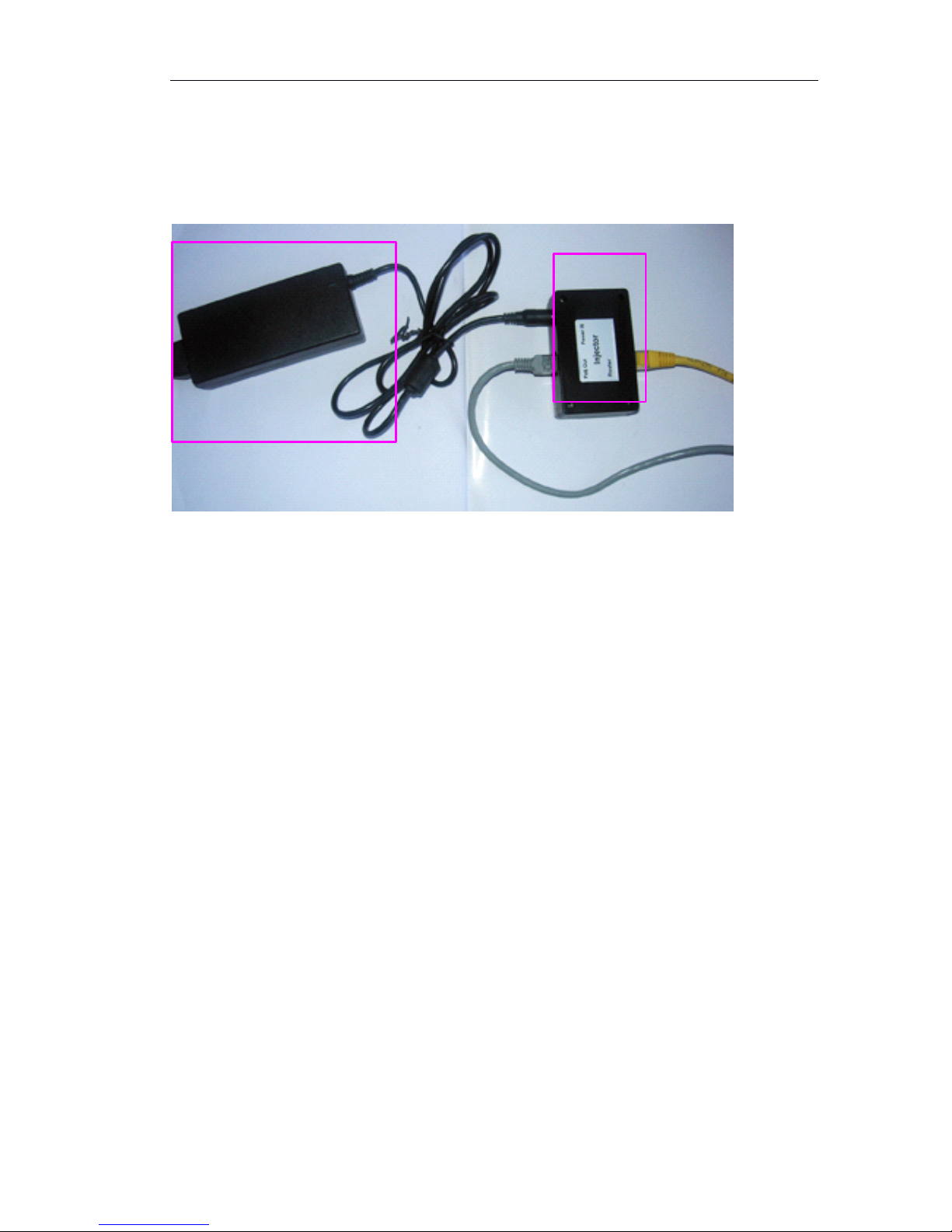
If you switch/router does not support PoE, use a PoE injector to connect between the
IP camera and non-PoE switch/router.
Make sure the power is off before you do the following steps:
Step1: Insert the Power
Power
Power
Power adaptor(48V
adaptor(48V
adaptor(48V
adaptor(48V 1A)
1A)
1A)
1A) of PoE IP Camera to the “ Power
Power
Power
Power in
in
in
in ”
”
”
” of the
‘ PoE Injector ”
Step2: Connect the “ PoE
PoE
PoE
PoE Out
Out
Out
Out ” of the “ PoE Injector ” to the “ PoE
PoE
PoE
PoE IP
IP
IP
IP Camera
Camera
Camera
Camera ”
Step3: Connect the Yellow
Yellow
Yellow
Yellow network
network
network
network cable
cable
cable
cable from “ PoE Injector ” to the “ Router
Router
Router
Router ”
Step4: Then power on the Power
Power
Power
Power Adaptor(48V
Adaptor(48V
Adaptor(48V
Adaptor(48V 1A)
1A)
1A)
1A) of
of
of
of Poe
Poe
Poe
Poe IP
IP
IP
IP Camera
Camera
Camera
Camera
4.2
4.2
4.2
4.2 Software
Software
Software
Software Installation
Installation
Installation
Installation
Our IP camera provides access through Internet Explorer or Management Software.
You need to set up the network settings and the IP address for the IP device. Please
make sure all connections are properly connected, then follow the procedures below.
4.2.1
4.2.1
4.2.1
4.2.1 Using
Using
Using
Using Web
Web
Web
Web Browsers
Browsers
Browsers
Browsers
1
1
1
1 Setup
Setup
Setup
Setup your
your
your
your PC
PC
PC
PC network
network
network
network
The IP address for your PC must be within the same subnet as the IP camera. You need
to match the TCP/IP Settings between PC and IP Camera before you can access it
The
The
The
The Power
Power
Power
Power adaptor
adaptor
adaptor
adaptor of
of
of
of Poe
Poe
Poe
Poe
IP
IP
IP
IP camera:
camera:
camera:
camera:
POE
POE
POE
POE
Injector
Injector
Injector
Injector
Page 10

Page 10 of 87
through IE.
2
2
2
2 Setup
Setup
Setup
Setup IP
IP
IP
IP Camera
Camera
Camera
Camera ’
’
’
’ s
s
s
s IP
IP
IP
IP address
address
address
address
The IP camera ’ s IP address can be assigned manually or acquired automatically by
network service (DHCP). If it acquired the IP address by using the DHCP service, please
use the management software bundled in the CD to find the IP address for all IP
came ras. The factory default setting is assigned manually IP address.
3
3
3
3 Setup
Setup
Setup
Setup your
your
your
your PC
PC
PC
PC network
network
network
network
To set up the network of IP camera via a PC, you have to change the TCP/IP settings
of the PC.
The following are the default network settings of IP camera.
IP address:192.168.188.188
Subnet mask:255.255.255.0
To access the IP camera, the IP address of the PC should match the address below.
IP address:192.168.188.XXX
Subnet mask:255.255.255.0
Note:
Note:
Note:
Note: XXX should be a number from 1 to 254 except 188, which is used by the IP
camera. Please also make sure that no two devices use the same IP address in the
same network.
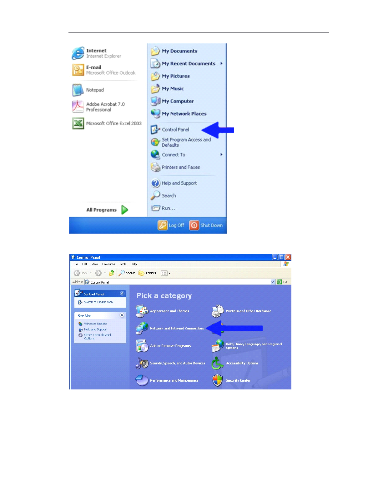
The procedures below are the setup procedure on Windows XP.
Step 1: Start up your PC
Step 2:Click the “ Start ” and select the “ Control panel ”
Page 11
Page 11 of 87
Step 3:Double click the “ Network and Internet connections ” icon.
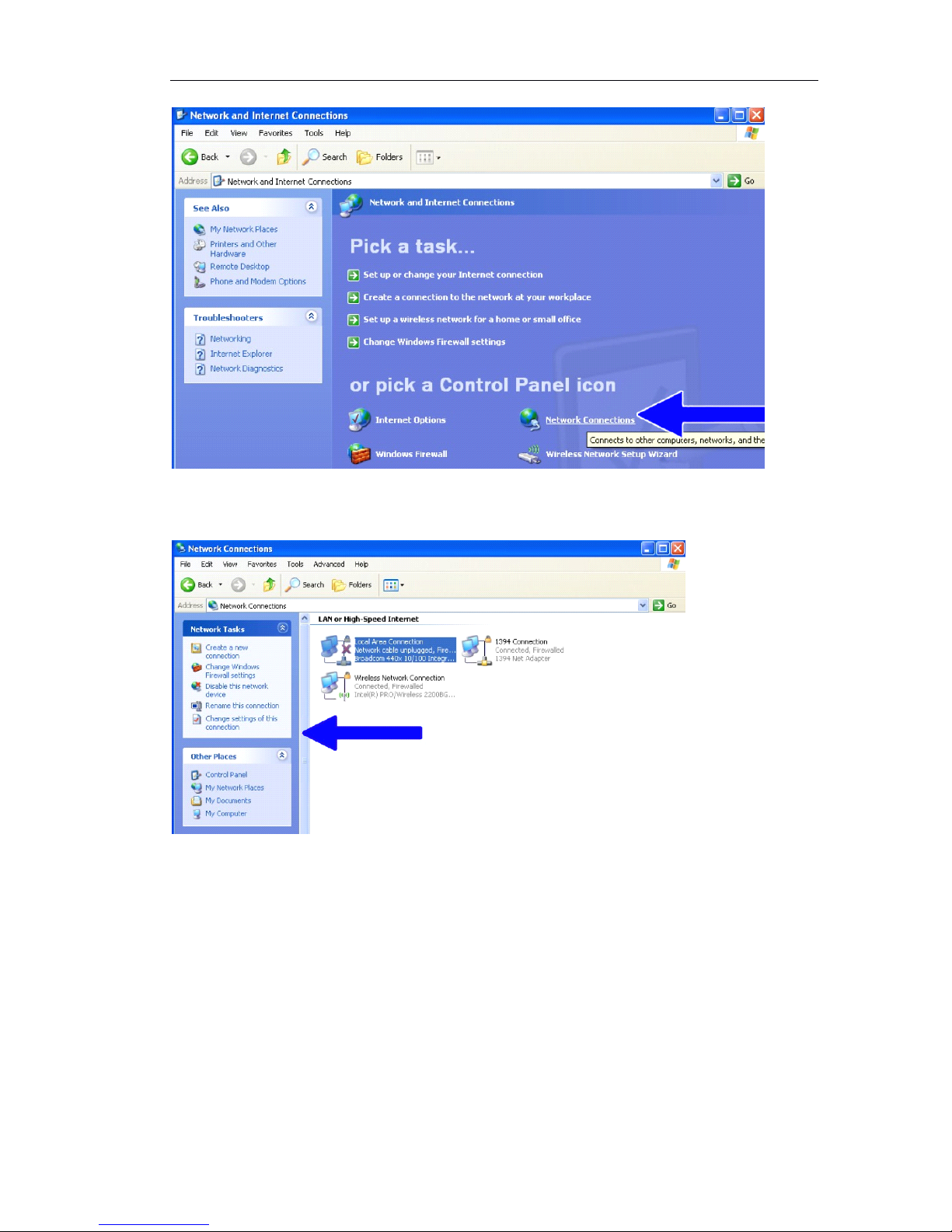
Step 4:Double click the “ Network connection ” icon
Page 12
Page 12 of 87
Step 5:Click “ Local Area Connections ”
,
then click “ Change settings of this
connection ” in the network task menu.
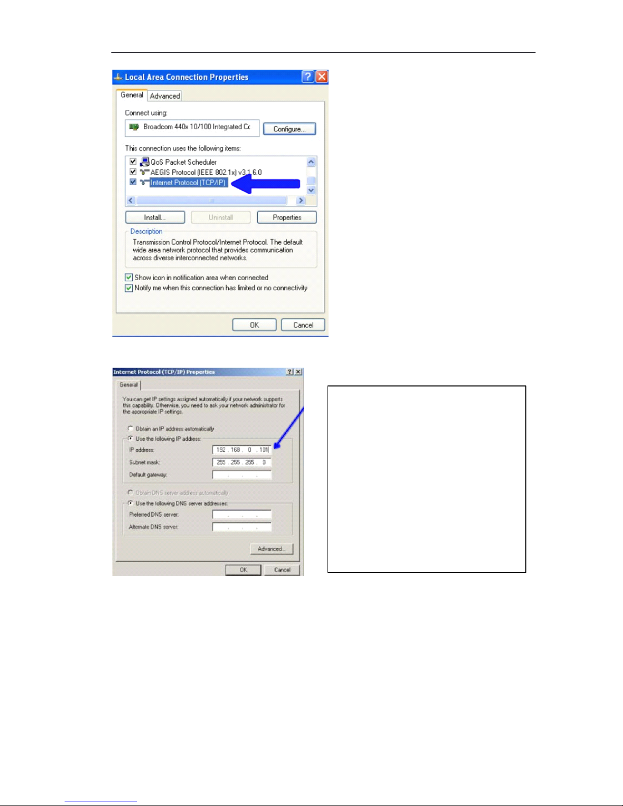
Step 6: Click “ Internet Protocol (TCP/IP ) ”,and click the click the “ Properties ” button. If
you have both IPv4 and IPv6, choose IPv4.
Page 13
Page 13 of 87
Step 7: Click the “ Use the following IP address ” radio button and enter the IP address
and the subnet mask.
Step 8: Click the “ Ok ” button and window dialog box closes.
4
4
4
4 Configure
Configure
Configure
Configure the
the
the
the IP
IP
IP
IP camera
camera
camera
camera
This section describes how to configure the IP camera. The administrator has unlimited
access to all settings.
Following the procedures below to configure the IP camera.
Step 1: Open your web browser (Microsoft Internet Explorer). Check your Internet
Explorer version is 6.0 or above version. If not, please update your IE to the higher
version.
Step 2: Enter the IP address of Ip camera in the address field. Press Enter.
To access the IP camera, the IP
address of the PC should match the
address below.
IP address : 192.168.188.XXX
Subnet mask : 255.255.255.0
Note:
Note:
Note:
Note: XXX should be a number from 1
to 254 except 188, which is used by
the IP camera. Please also make sure
that no two devices use the same IP
address in the same network.
Page 14
Page 14 of 87
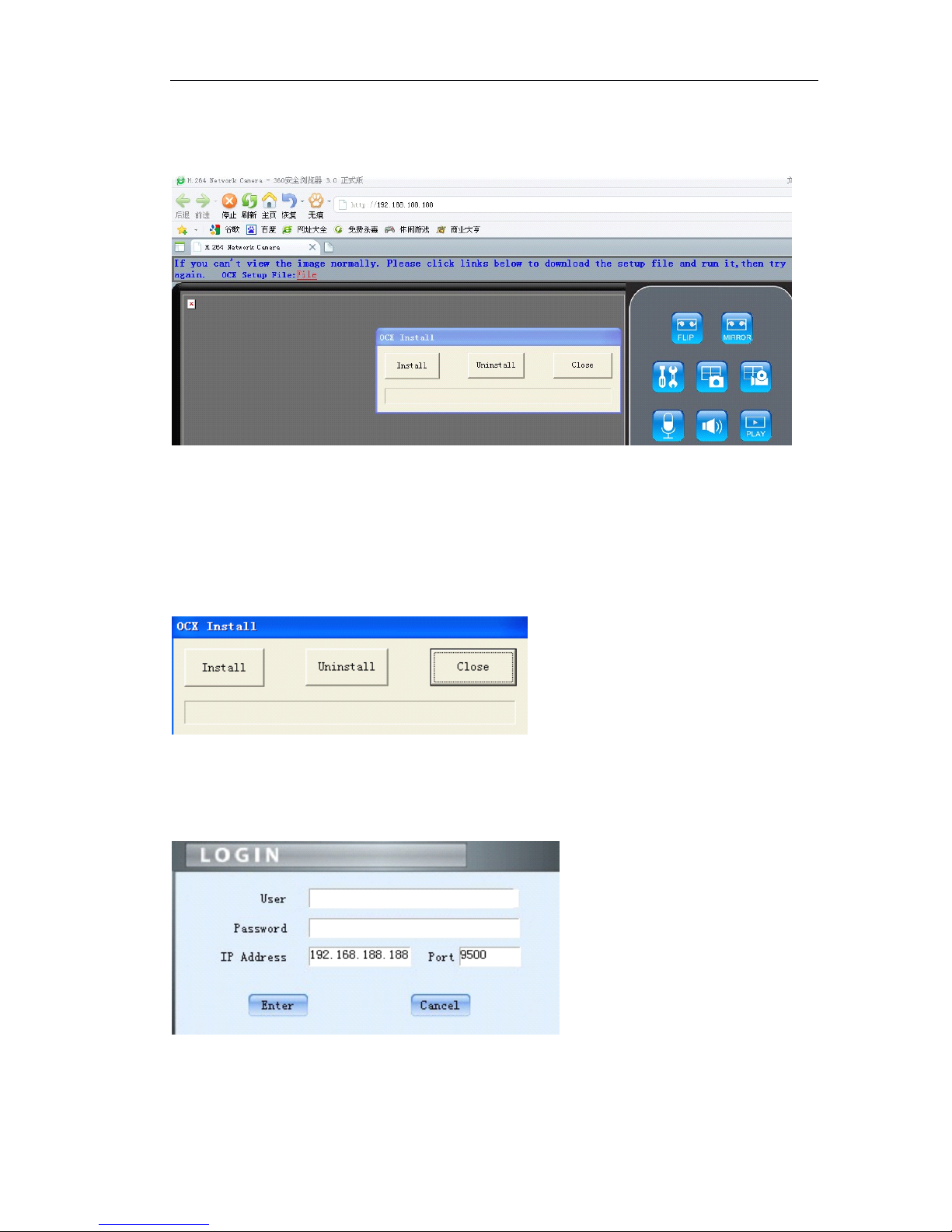
The default IP address is 192.168.188.188.
Step 3: The login page is now displayed as below
Step 4: Click 『 Install 』 to install the OCX.
If it does not pop up the OCX install dialog, Click 『 File 』 to download the OCX.
Then, i t will pop up a new dialog, click 『 Run 』 or 『 Save 』 to download OCX .
After download it , double-click the downloaded file “ DVSClientx.exe ” to install
it.
Step 5: Refresh your web browser
Step 6: Enter the IP address.
It will ask for the password and user name.
Enter user name: admin ( default setting for administrator ) and password :
admin ( default setting for administrator )
Step 7: Click the “ Enter ” button to login or click the “ cancel ” button to close the login
Page 15
Page 15 of 87
page.
Once you log in successfully,the “ video display page ” will be shown.
Skill
Skill
Skill
Skill :
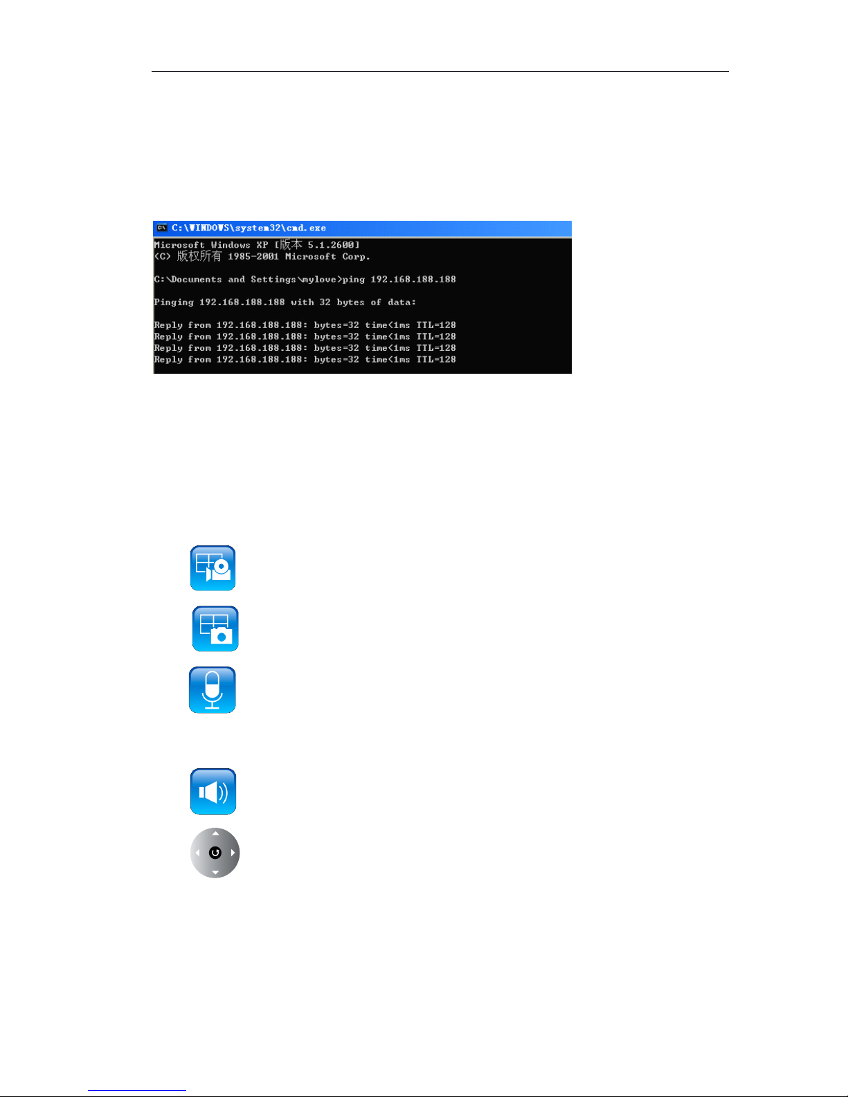
Test network connection between IP camera and PC successfully or not.
In WINDOWS, click<Start → run → cmd , you can see the DOS window and input
“ 192.168.188.188 ” . That proves IP camera or NVS is working if the mention is same to
above picture.
4.2.1.1
4.2.1.1
4.2.1.1
4.2.1.1 Live
Live
Live
Live view
view
view
view over
over
over
over IE
IE
IE
IE
In the Liveview interface, User can do the operations as snapshot, record, talk,
pan tilt zoom control.
Click to start manual record, and re-click to stop manual record.
Click to capture and save still images.
Click to talk to people around the IP camera. Audio will project from the
external speaker connected to the IP camera. Click this button again to end talking
transmission.
Click to turn on/off the volume on the local computer.
Click to control PTZ . Turn up, down, left, right, automatic, call preset, set
preset point.
Page 16
Page 16 of 87
4.2.1.2
4.2.1.2
4.2.1.2
4.2.1.2 Live
Live
Live
Live view
view
view
view setting
setting
setting
setting
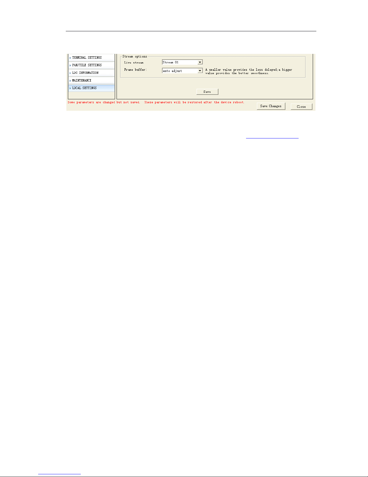
『 Live Stream 』 Live stream can set to Stream 01 mode or Stream 02 mode.
OMC-900IP Series IP Camera support dual streaming for live view, local storage and
network transmission. As the dual stream setting, you can refer 5.1.1 Video setting
4.2.2
4.2.2
4.2.2
4.2.2 CMS
CMS
CMS
CMS Installation
Installation
Installation
Installation
4.2.2.1
4.2.2.1
4.2.2.1
4.2.2.1 PC
PC
PC
PC requirements
requirements
requirements
requirements
Basic Configuration of Client PC
Motherboard: Pentium IIII 2.8GHz
Memory: 512M
Display Card: TNT2
Recommended Configuration of Client PC
Motherboard: Dual-core 2.6GMhz
Memory: 1G
Display Card: George FX5200 or ATI 7000(9000) Series 256MB
4.2.2
4.2.2
4.2.2
4.2.2 CMS
CMS
CMS
CMS Installation
Installation
Installation
Installation
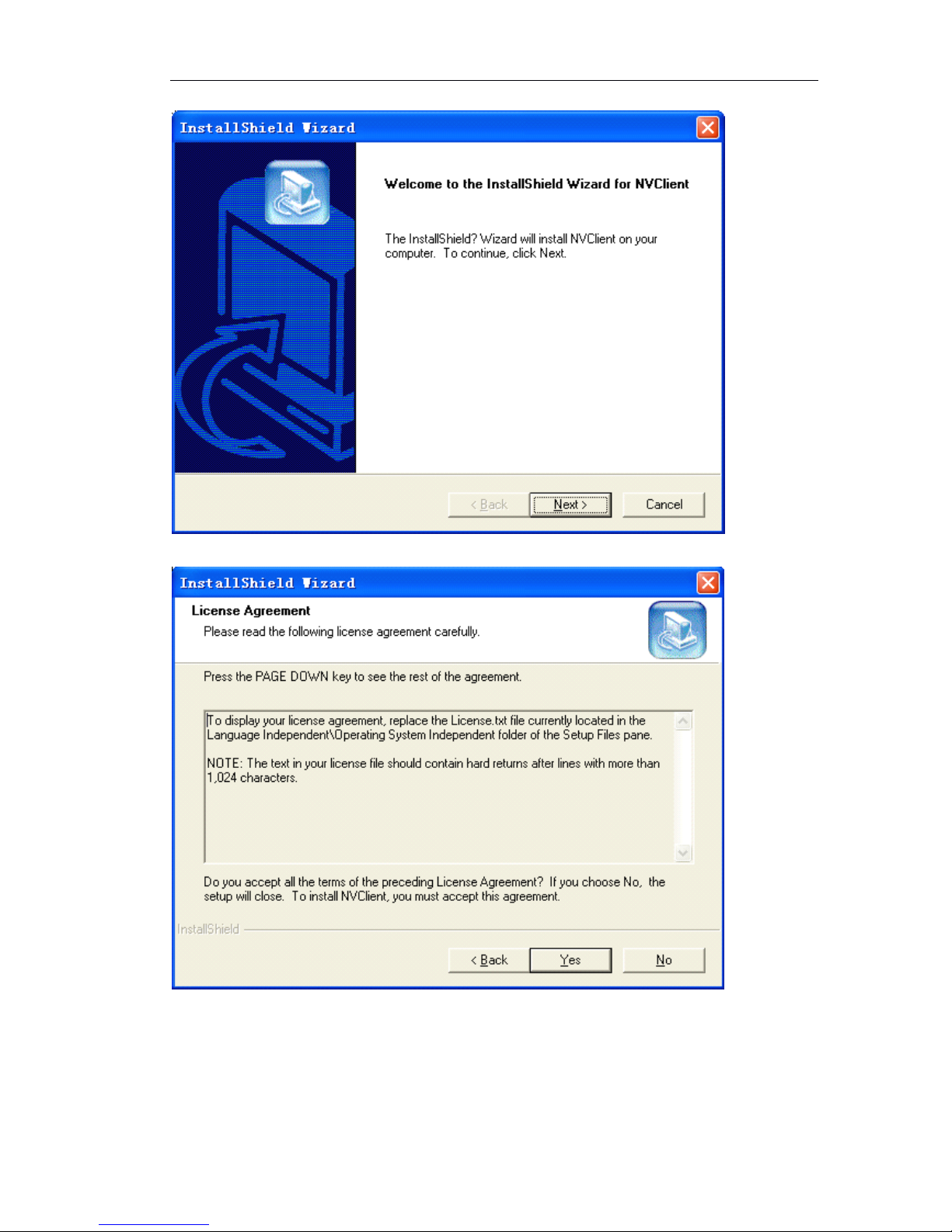
Run setup on windows, double click your left mouse button, it will be an “ installation
wizard ” dialogue box, as following figure:
Page 17
Page 17 of 87
Click “ next ”,there will be a dialogue box:
Click “ Yes ”,there will be a dialogue box:
Page 18
Page 18 of 87
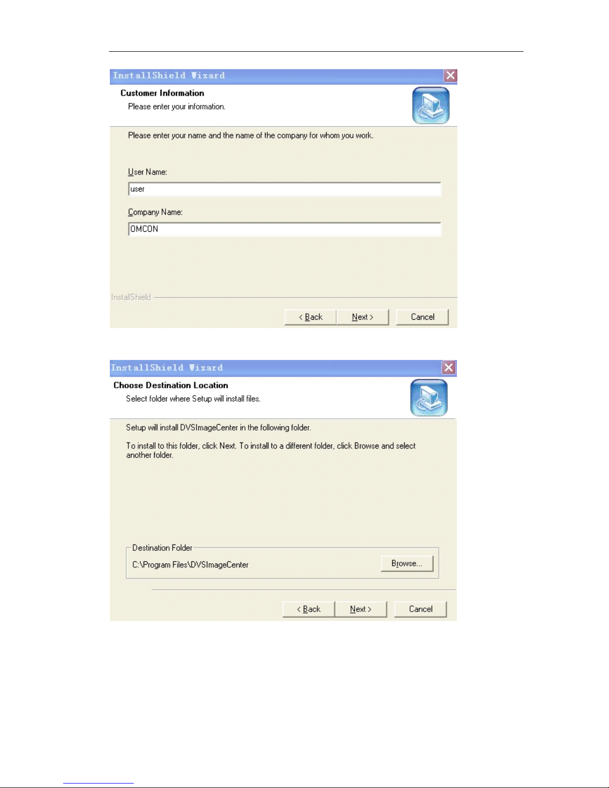
Input user name and company name (optional), click “ Next ”,there will be a dialogue
box:
Choose installation folder, click “ next ”,there will be a dialogue box:
Page 19
Page 19 of 87
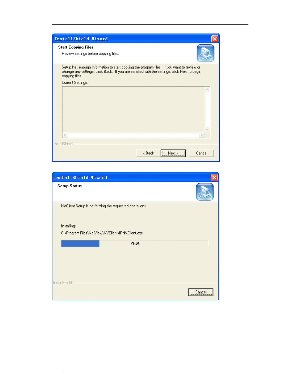
Click “ Next ”,move to the installation process
When the installation is finished, there will be a dialogue box
Click
Click
Click
Click “
“
“
“ continue
continue
continue
continue ”
”
”
” and
and
and
and finish the installation
CMS is installed into the system default directory and there will be a “ CMS ” program
group on the “ Start ” ” Program ” of the windows system
Page 20
Page 20 of 87
4.2.
4.2.
4.2.
4.2. 3
3
3
3 How
How
How
How to
to
to
to obtain
obtain
obtain
obtain IP
IP
IP
IP address?
address?
address?
address?
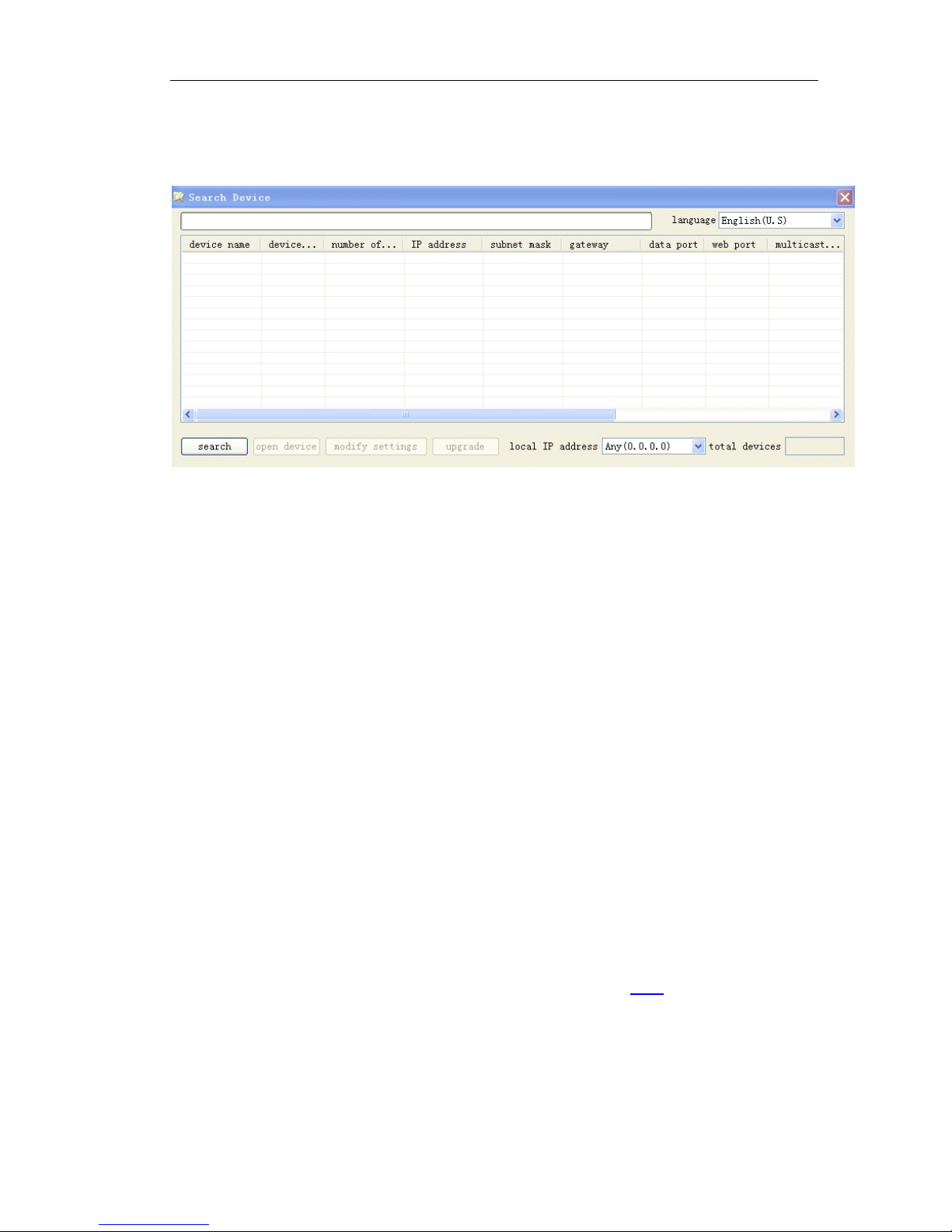
After install the CMS, click 『 Start
』 『
Program
』 『
Search 』
Pops up the following figure
Click “ search ”,you can know the IP address of all IP cameras which connected in the
network. Make sure each IP camera has one individual IP address.
4.
4.
4.
4. 3
3
3
3 IP
IP
IP
IP Surveillance
Surveillance
Surveillance
Surveillance System
System
System
System Connection
Connection
Connection
Connection
Setting
Setting
Setting
Setting up
up
up
up the
the
the
the IP
IP
IP
IP camera
camera
camera
camera over
over
over
over the
the
the
the Internet
Internet
Internet
Internet
This section explains how to setup the IP camera to an Internet connection.
1 If you have external devices such as sensors, sound pick-up, speaker, Pan tilt unit,
make the connection.
2 Connect the IP camera to a switch by Ethernet cable
3 Connect the power cable from IP camera to a power outlet.
There are several ways to set up the IP camera over the Internet. The first way is to set
up the IP camera behind a router. The second way is to use PPPoE.
Internet
Internet
Internet
Internet connection
connection
connection
connection by
by
by
by a
a
a
a router
router
router
router
Before setting up the IP camera over the internet, make sure you have a router and
follow the steps below.
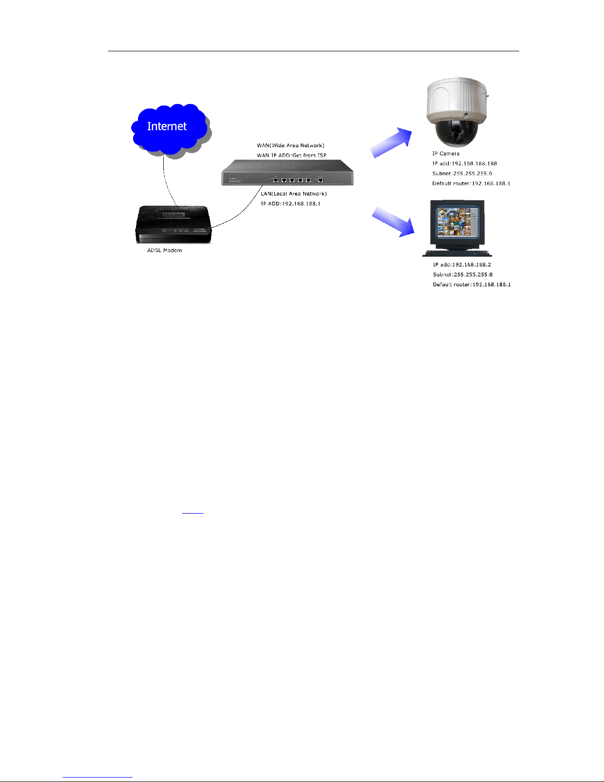
1 Connect your IP Camera behind a router, the internet environment is illustrated
below. Regarding how to obtain your IP address, please refer 4.2.3
Page 21
Page 21 of 87
2 If LAN IP address of your IP camera is 192.168.188.188, please forward the following
ports for the IP camera on the router
WEB Port and Data Port
If you have changed the port numbers on the Network page, please open the ports
accordingly on your router. For information on how to forward ports on the router,
please refer to your router ’ s user ’ s manual.
3 Find out the public IP address of your router provided by your ISP (Internet Service
Provider). Use the public IP and the secondary HTTP port to access the IP camera from
the Internet.
Internet
Internet
Internet
Internet connection
connection
connection
connection by
by
by
by PPPoE
PPPoE
PPPoE
PPPoE (Point-to-Point
(Point-to-Point
(Point-to-Point
(Point-to-Point over
over
over
over Ethernet)
Ethernet)
Ethernet)
Ethernet)
Choose this connection type if you are connected to the Internet by a DSL Line.
Please refer for 5.3.2 PPPoE details
5
5
5
5 IP
IP
IP
IP camera
camera
camera
camera configuration
configuration
configuration
configuration
There are following types of OMC-900IP network camera parameter configuration:
1) Set IP camera parameter via management software
2 ) Set IP camera parameter via IE
OMC-900IP Network Camera supports remote view, parameter setting and remote
control via software and IE
Use configuration tool
Page 22
Page 22 of 87
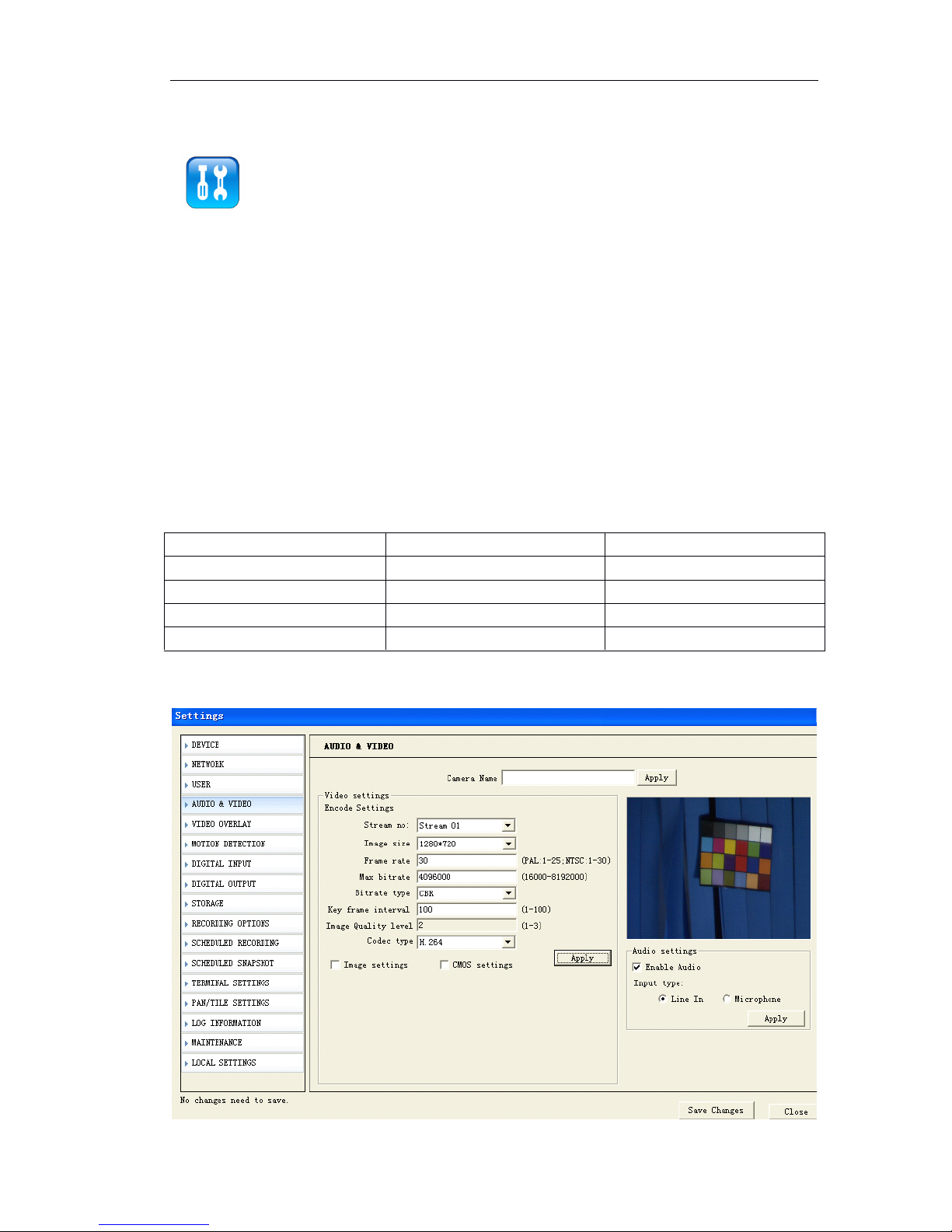
When you login the server successfully with IE, you can use the convenient
configuration tool provided by us to configure the Network Camera. Click
“ parameter setting ” with left mouse button, configuration tool will pop-up a
new page, displayed as following:
5.1
5.1
5.1
5.1 video
video
video
video and
and
and
and audio
audio
audio
audio settings
settings
settings
settings (General,
(General,
(General,
(General, OSD
OSD
OSD
OSD display,
display,
display,
display, Audio
Audio
Audio
Audio
Setting)
Setting)
Setting)
Setting)
5.1.1
5.1.1
5.1.1
5.1.1 Video
Video
Video
Video setting
setting
setting
setting
Video setting includes the image size(resolution),Frame Rate, key Frame interval,
compression format, dual streaming and bit rate settings. (Details are described in the
next part “ advanced image setting skills ” )
『 Video Format 』 Image setting. It is adjusting the resolution, please refer to the table:
Note:
Note:
Note:
Note: 2Megapixel and 1.3Megapixel are available for OMC-900IPMEGA Series
Megapixel IP camera.
Resolution
Image size
Frame rate (Max)
2Megapixel
1600*1200
15FPS
1.3Megapixel
1280*720
30FPS
VGA
640* 480
30FPS
QVGA
320*176
30FPS
Page 23

Page 23 of 87
『 Stream no』You can define dual streaming for local storage and network transmissio n.
Stream 01 is for local storage . Stream 02 is for network transmission.
If you don ’ t set stream 02, stream 01 can work both local storage and network
transmission.
『 Image size 』 If stream 01 mode, the resolution can set to 1600*1200 (2megapixel);
1280*720(1.3Megapixel)
If stream 02 mode, the resolution can set to 640*352 (VGA); 320*176 (QVGA)
『 Frame Rate 』 It means how many frames the encoder is encoding per second. For
details please refer to table 1.
『 Key Frame Inv 』 It means the number of frame P or frame B between key frames
(frame I)
『 Rate Type 』 When the VBR(Variable Bit rate) is chose, the Network Camera will
automatic choose a proper stream according to the complex and movement
condition of images and the image quality set by user, but the “ stream rate ” will not
exceed. When the CBR (Constant Bit rate) is chose, the Network Camera will control
the “ stream rate ” in the setting.
『 Image Quality level 』 It is an important parameter that controls image quality, it can
be set in 3 levels. For setting please refer to “ advanced image setting skill ”
『 Bit Rate 』 “ Bit Rate ” means the amount of stream bit encoding by encoder in a
second, the unit of stream rate is bps, namely bits per second. The range of stream
rate is from 16k to 8192k, please note that the unit k means 1000, for example 8192k
means 819 2000bps, the encoder will use 819200bps stream rate to encode video.
For more details of setting of the above part please refer to the following “ advanced
image setting skill ”
『 Code type 』 Support dual compression, H.264 or MJPEG.
Advanced
Advanced
Advanced
Advanced image
image
image
image setting
setting
setting
setting skill
skill
skill
skill
Image setting is an important part in the server setting because it will affect the
system ability, it has close relationship with the video quality and network ability. The
aim of image setting is to make it conveniently suitable for various networks.
Bit stream and frame rate settings are providing in system, but it is hard to suit
various networks with only several default values. Consequently, some advanced
settings are providing for user to ensure the video quality while utilizing network
effect ively.
The image settings including 『 Bit Rate』,
『 Frame Rate』,
『 Key Frame Inv』,
『 Rat e type
』
and 『 Image Quality level 』 are what we concern about.
Now we will introduce meaning, effect to other settings and network ability of each
setting respectively.
Bit
Bit
Bit
Bit Rate
Rate
Rate
Rate
It means the size of stream bit encoding by encoder per second. The unit is bit per
second. this setting is the main factor affects the bandwidth of network and other
settings. The bandwidth utilizing will increase when the bit rate increase. Thus CBR
(Co nstant Bit rate) setting according to the bandwidth is suitable for the network
Page 24

Page 24 of 87
bandwidth limitation situations. In the same quality situation, bit rate will be affected
by settings frame rate, I frame Inv, rate type, image quality, and definition. Please refer
to following introduction for details. This parameter is valid when the “ Rate Type ” is set
as CBR (Constant Bit rate).
Frame
Frame
Frame
Frame Rate
Rate
Rate
Rate
It means the maximum number of frames that encoder encode per second, with unit
frame per second. This setting has three functions, firstly the number of frames encoder
encoding per second is set by this setting, secondly when the stream rate is CBR
(Con stant Bit rate), when the frame rate changed, for example decreased, because
the encoder need to keep the current code stream setting, thus it will enhance the
frame quality according to the current code stream setting. It means, when the code
stream is V BR (Variable Bit rate), the decreasing of frame rate will enhance the quality
of video and keep the same frame rate value. The video quality will reduce conversely .
Thirdly, when the same quality is kept, the increasing frame rate will make the image
smoo ther and stream rate increasing. Conversely, the image will become
discontinuous and stream rate decrease.
Key
Key
Key
Key Frame
Frame
Frame
Frame Inv
Inv
Inv
Inv
It means the number of frame P or frame B between key frames (frame I). Generally,
the default value of this parameter is 25 and does not need to be changed. When the
stream rate is settled, the increasing of this value will make the quality of video bett er.
When the video keeps the same quality, this value increasing will make stream rate
increased. Conversely, the stream rate will decrease.
Rate
Rate
Rate
Rate Type
Type
Type
Type
When the VBR (Variable Bit rate) is chose, the front end will automatic choose a
proper stream according to the complex and movement condition of images and the
image quality set by user, but the “ Bit Rate ” will not exceed. When the CBR (Constant
Bit rate ) is chose, the front end will control the “ Bit Rate ” in the setting.
Image Quality
It is an important parameter that controls image quality, this parameter is valid when
the “ Rate Type ” is set as VBR (Variable Bit rate).
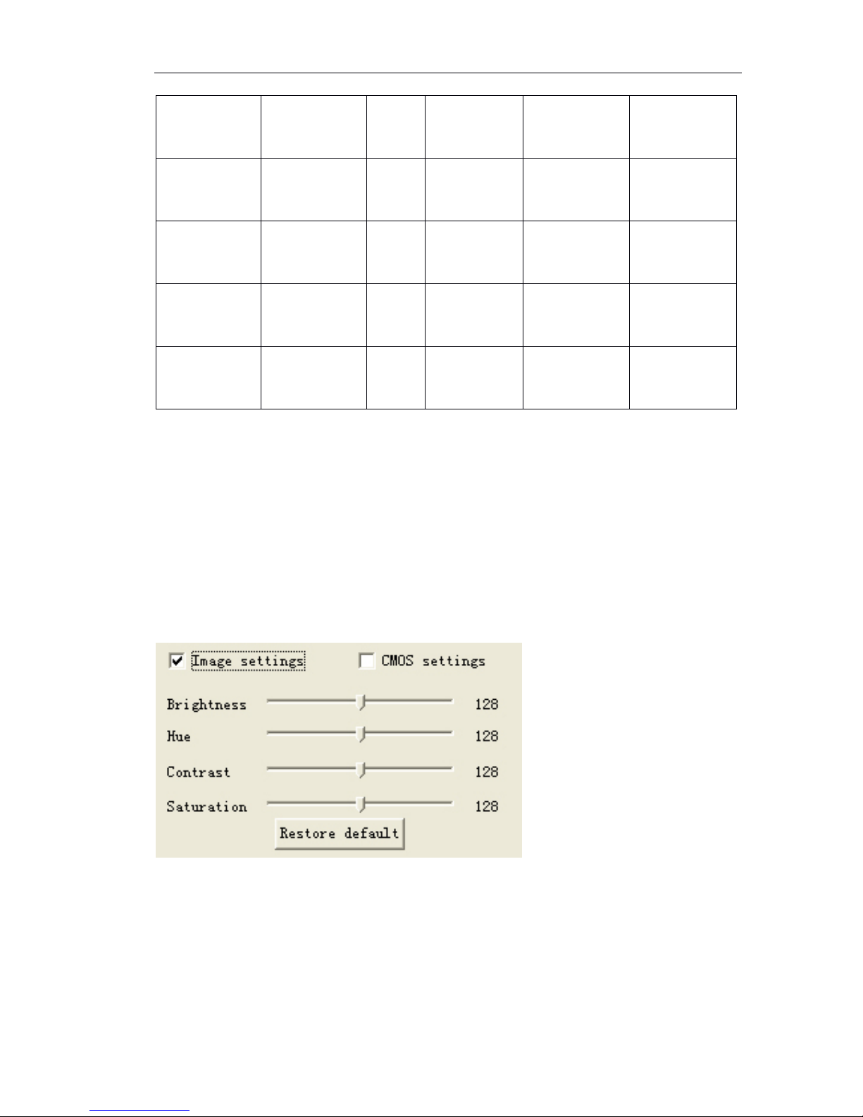
To sum up, please refer to our reference value for various conditions and the
information giving above to adjust the image setting. You can make adjusting
according to the above description if the quality of video is not satisfied.
Reference
setting
Attribute
Frame
rate
Rate type
Bit rate
Stream mode
CBR
(Constant Bit
rate)
CBR
(Constant Bit
rate)
25
CBR
(Constant
Bit rate)
Set
according
condition
Set
according
condition
LAN
VBR
(Variable Bit
rate)
25
VBR
(Variable Bit
rate)
Unlimited
Stream 01 or
stream 02
ADSLupload 512k
CBR
(Constant Bit
rate)
12
CBR
(Constant
Bit rate)
384k
Stream 02
Page 25
Page 25 of 87
Notice: pleas slightly adjust values referring to above reference values according to
the system condition. You can make necessary adjusting according to the description
of each setting if you have strict requirements for the image quality and bandwidth.
5.1.2
5.1.2
5.1.2
5.1.2 Image
Image
Image
Image setting
setting
setting
setting
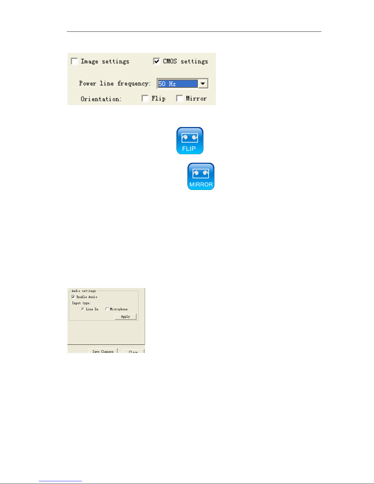
『 Image setting
』
Image setting includes the brightness, contrast and Hue. The left of t he
setting bar is the minimum value, you can easily drag the bar control to change value
by mouse. Click 『 Restore default 』 to load the factory settings.
ADSL-upload
1M
CBR
(Constant Bit
rate)
12
CBR
(Constant
Bit rate)
512k
Stream 02
ADSL-upload
2M
CBR
(Constant Bit
rate)
25
CBR
(Constant
Bit rate)
768k
Stream 02
Best
VBR
(Variable Bit
rate)
25
VBR
(Variable Bit
rate)
Unlimited
Set
according
condition
Good
VBR
(Variable Bit
rate)
25
VBR
(Variable Bit
rate)
Unlimited
Set
according
condition
Normal
VBR
(Variable Bit
rate)
25
VBR
(Variable Bit
rate)
Unlimited
Set
according
condition
Page 26
Page 26 of 87
5.1.3
5.1.3
5.1.3
5.1.3 Video
Video
Video
Video Flip
Flip
Flip
Flip and
and
and
and Mirror
Mirror
Mirror
Mirror
『 Power line frequency 』 For different countries, it has different frequency. If image
flickers, may the setting of power line frequency is not correct
『 Flip 』 vertical reversal or click
『 Mirror 』 horizontal reversal or click
After setting, click the 『 apply 』 button.
5.1.4
5.1.4
5.1.4
5.1.4 Audio
Audio
Audio
Audio setting
setting
setting
setting
『 Enable Audio』Clicking “√” on “□” in the “ Enable Audio ” means the system will enco de
audio and send encoded audio stream to the client via network.
If audio input device is microphone, click 『 Microphone 』 .
If audio input device is sound amplifier,choose 『 line in 』 .
After setting, click 『 Apply 』 button.
5.2
5.2
5.2
5.2 OSD/MASK
OSD/MASK
OSD/MASK
OSD/MASK setting
setting
setting
setting
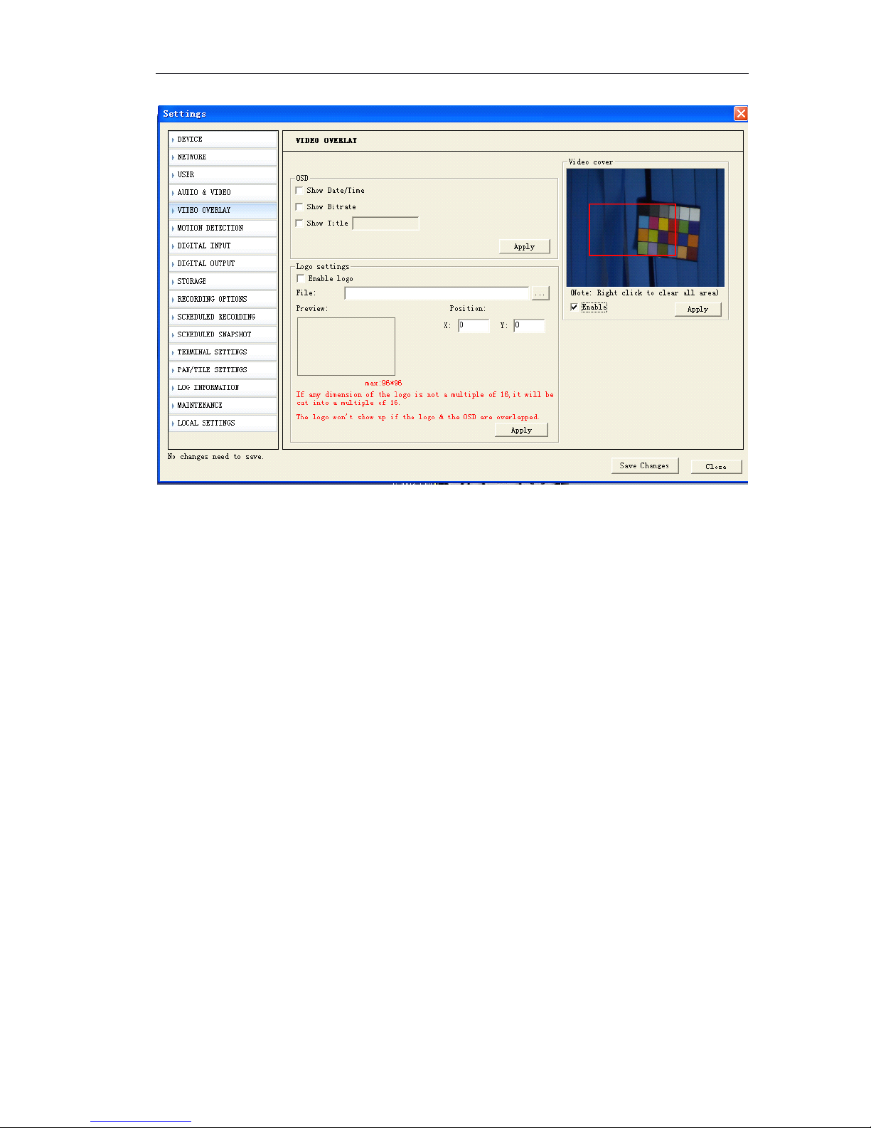
The “ OSD setting ” shown as following figure includes the OSD/MASK setting. In the
setting “√” in “□” means enable the corresponding overlay option function, contrarily
disable the corresponding function.
Page 27
Page 27 of 87
『 OSD 』 This setting achieves the characters overlay function, including date overlay,
time overlay, channel description overlay, frame rate and bit rate display. They are
displayed on the top left of the live view video.
『 Video Cover
』 :
This setting achieves the video mask setting function on specific zone .
『 Enable
』
Drag the left button of mouse to draw a zone where you would like to shelt er
on the image and click 『 Apply 』 . If you would like to cancel the shelter setting, no
need
click “√” in “□” .
5.3
5.3
5.3
5.3 network
network
network
network settings
settings
settings
settings (General,
(General,
(General,
(General, DHCP,
DHCP,
DHCP,
DHCP, PPPoE,DDNS,
PPPoE,DDNS,
PPPoE,DDNS,
PPPoE,DDNS, FTP,
FTP,
FTP,
FTP, E-mail,
E-mail,
E-mail,
E-mail,
Wifi,
Wifi,
Wifi,
Wifi, 3G)
3G)
3G)
3G)
5.3.1
5.3.1
5.3.1
5.3.1 General
General
General
General setting
setting
setting
setting
Page 28
Page 28 of 87
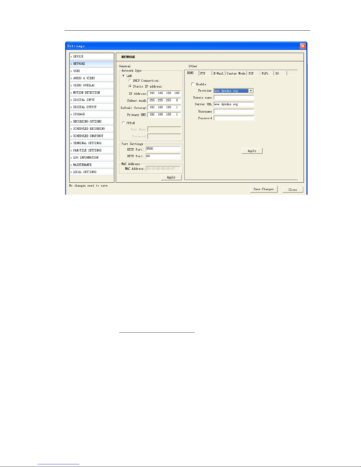
『 DHCP 』 Click this to enable IP camera ’ s DHCP function. It acquires its WAN port IP
address from a DHCP server within the same network. (You must have a DHCP server in
order to enable this function.)
『 Static IP address 』 Click this to manually enter the IP camera address.
IP address is the address of Network Camera in network, please enquire this value from
your network administrator, invalid or address conflict will cause Network Camera
connection failed. Default IP address is 192.168.188.188
『 Subnet mask 』 If IP address is changed, adjust the subnet mask accordingly.
『 Gateway 』 Enter the IP address of the gateway (router). Please enquire your network
administrator.
『 DNS 』 Defines the IP address of the primary DNS server. This is used for identifying this
computer by name instead of IP address .
『 RTSP Port 』 it is the listening port providing data servers including video and audio
stream service and setting service.
『 HTTP port』it is the listening port providing web service. If this setting is changed, plea se
login by accessing http://IP address: web port
『 Apply 』 Click this button when you finished corresponding setting options.
Note:
Note:
Note:
Note: Once you finish all settings, make sure to click the “ Save changes ” button.
Otherwise, some settings may not take effect.
Page 29
Page 29 of 87
5.3.2
5.3.2
5.3.2
5.3.2 PPPOE
PPPOE
PPPOE
PPPOE
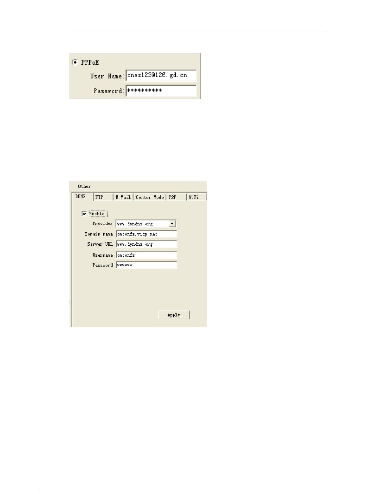
If IP Camera or video server is connect ed to xDSL modem directly, please set the
PPPoE here.
Enable PPPoE, enter user name and password of your xDSL account
5.3.3
5.3.3
5.3.3
5.3.3 DDNS
DDNS
DDNS
DDNS
A dynamic DNS (domain name system) service that allows your IP camera, especially
when assigned with a dynamic IP address, to have a fixed host and domain name.
『 Enable 』 :Click this to enable IP Camera ’ s the DDNS function.
DDNS function enables users to connect to this IP camera by domain name even if its
IP address is not static.
『 Static IP address』Provider: Select one of DDNS service provider from the drop-dow n
list. You can visit their website to get a DDNS service account for this Ip camera.
『 Domain Name 』 Enter the host name of your DDNS service account.
(ex.:usaipcamera.dyndns.org)
『 User Name 』 Enter the login user name for your DDNS service account.
『 Password 』 Enter the login password for your DDNS service account.
Page 30
Page 30 of 87
5.3.4
5.3.4
5.3.4
5.3.4 E-Mail
E-Mail
E-Mail
E-Mail Setting
Setting
Setting
Setting
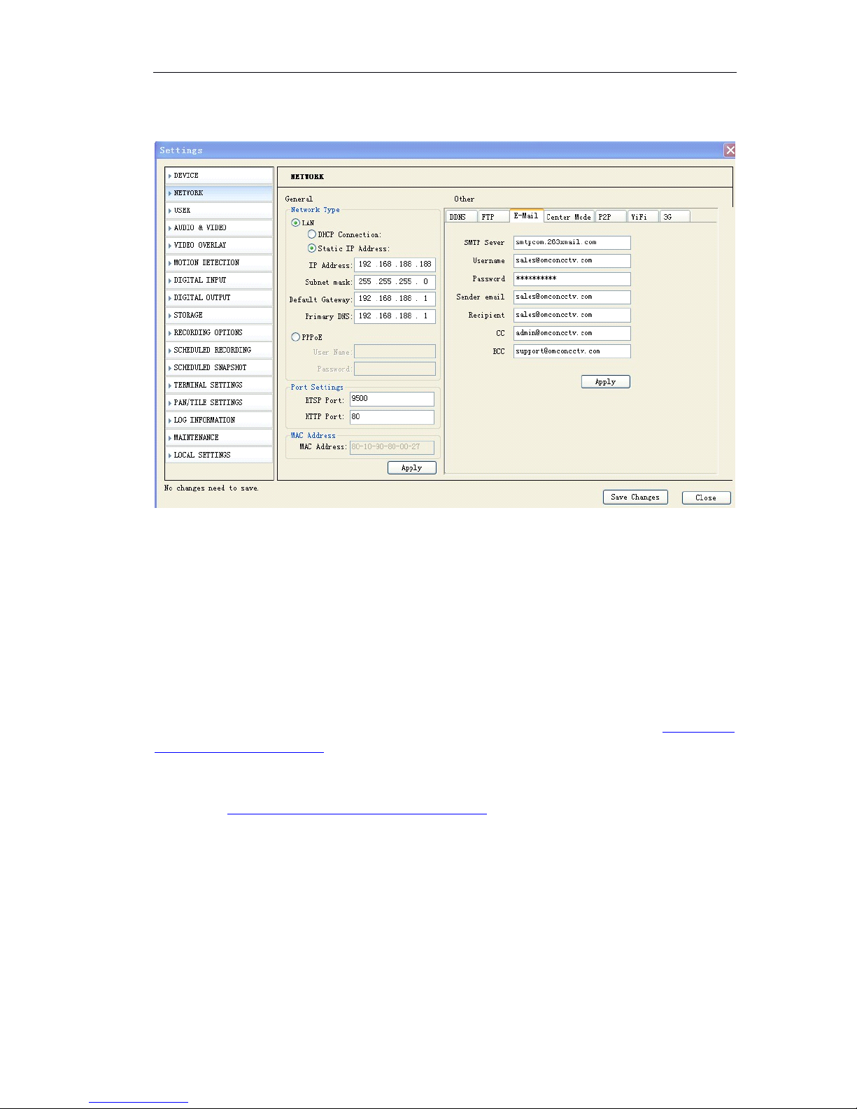
(1) 『 SMTP Server 』 Input the SMTP Server, e.g. smtp.sohu.com.
(2) 『 user name 』 Input the full name of email address.
(3) 『 password 』 Input password to login email address.
(4) 『 Sender email』Input the sending email address. Sending email address should b e
same as email address of 『 user name 』
(5) 『 Receipt 』 The email address which receive the alarm notification.
(6) 『 C.C 』 to make a copy to email address which can receive the alarm notification
(7) 『 BCC 』 Blind carbon copy email address which can receive the alarm notification
Click 『 Apply 』 to save the changes, click 『 Save changes 』 to save in Flash.
Note:
Note:
Note:
Note: When you want to send snapshot once motion detection, please set motion
detection paragements and enable 『 Motion Detection
』 『
Enable Snapshot 』 by
『 Email 』 .
When you would like to send snapshot once sensor alarm, please connect the alarm
sensor and set the parameters in 『 Digital input 』 and enable 『 Digital input
』 『
Enable
Snapshot 』 by 『 Email 』 .
5.3.5
5.3.5
5.3.5
5.3.5 FTP
FTP
FTP
FTP setting
setting
setting
setting
Page 31
Page 31 of 87
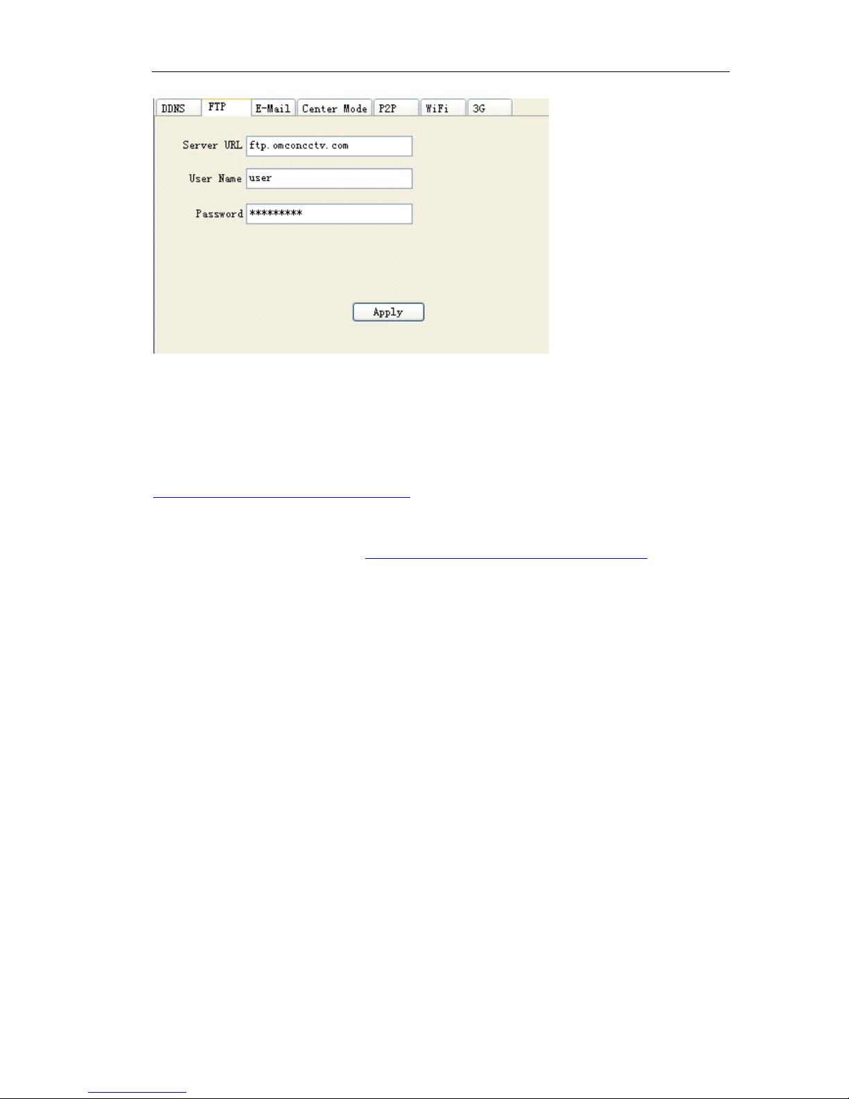
(1) 『 Server URL 』 Input the FTP Server
(2) 『 user name 』 Input the user name of FTP Server
(3) 『 password 』 Input password to FTP Server
Click 『 Apply 』 to save the changes, click 『 Save changes 』 to save in Flash.
Note:
Note:
Note:
Note: When you want to send snapshot to FTP Server once motion detection
,
please
set motion detection paragements and enable 『 Motion Detection 』 『 Enable
Snapshot 』 .
When you would like to send snapshot to FTP Server once sensor alarm, please
connect the alarm sensor and set the parameters in 『 Digital input 』 and enable
『 Digital input
』 『
Enable Snapshot 』 by 『 FTP 』 .
5.3.5
5.3.5
5.3.5
5.3.5 WIFI
WIFI
WIFI
WIFI setting
setting
setting
setting (Only
(Only
(Only
(Only for
for
for
for WIFI
WIFI
WIFI
WIFI IP
IP
IP
IP Camera
Camera
Camera
Camera models)
models)
models)
models)
Page 32
Page 32 of 87
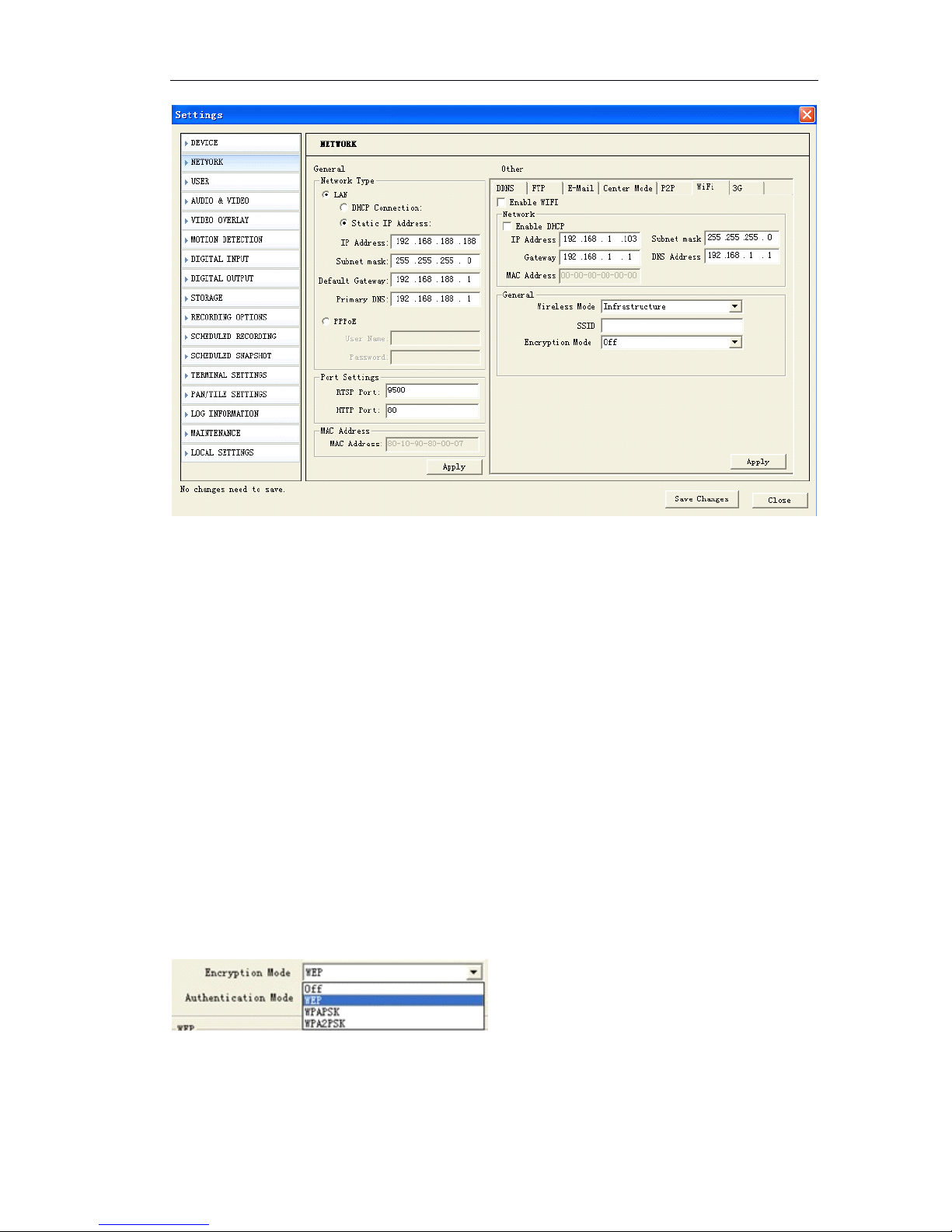
1 Check the SSID for your wireless access point (AP)
2 Enable WIFI.
3 Type in the SSID the same as your AP.
4 Select the wireless mode as “ Infrastructure ”
5 Clicks Apply.
『 Enable WIFI 』 Enable wireless network connection
『 IP Address 』 IP address of wireless router or AP.
『 Gateway 』 wireless network gateway
『 SSID 』 abbreviated from Service Set Identifier, is the name assigned to the wireless
network. Access points and wireless clients attempting to connect to a specific
WLAN(Wireless Local Area Network) must use the same SSID. The default setting is null.
『 Wireless mode 』 Click on the pull-down menu to select from the following options:
Infrastructure : Connect the IP camera to the WLAN by an Access Point.
Ad-Hoc: Connect the IP camera directly to a host equipped with a wireless adapter in
a peer-to-peer environment .
『 Encryption mode 』 Select the data encrypt method. There are four types: OFF,
WEP,WPA-PSK and WPA2-PSK.
1 Off: No data encryption
2 WEP(Wired Equivalent Privacy): This allows communication only with other devices
with identical WEP settings.
Page 33
Page 33 of 87
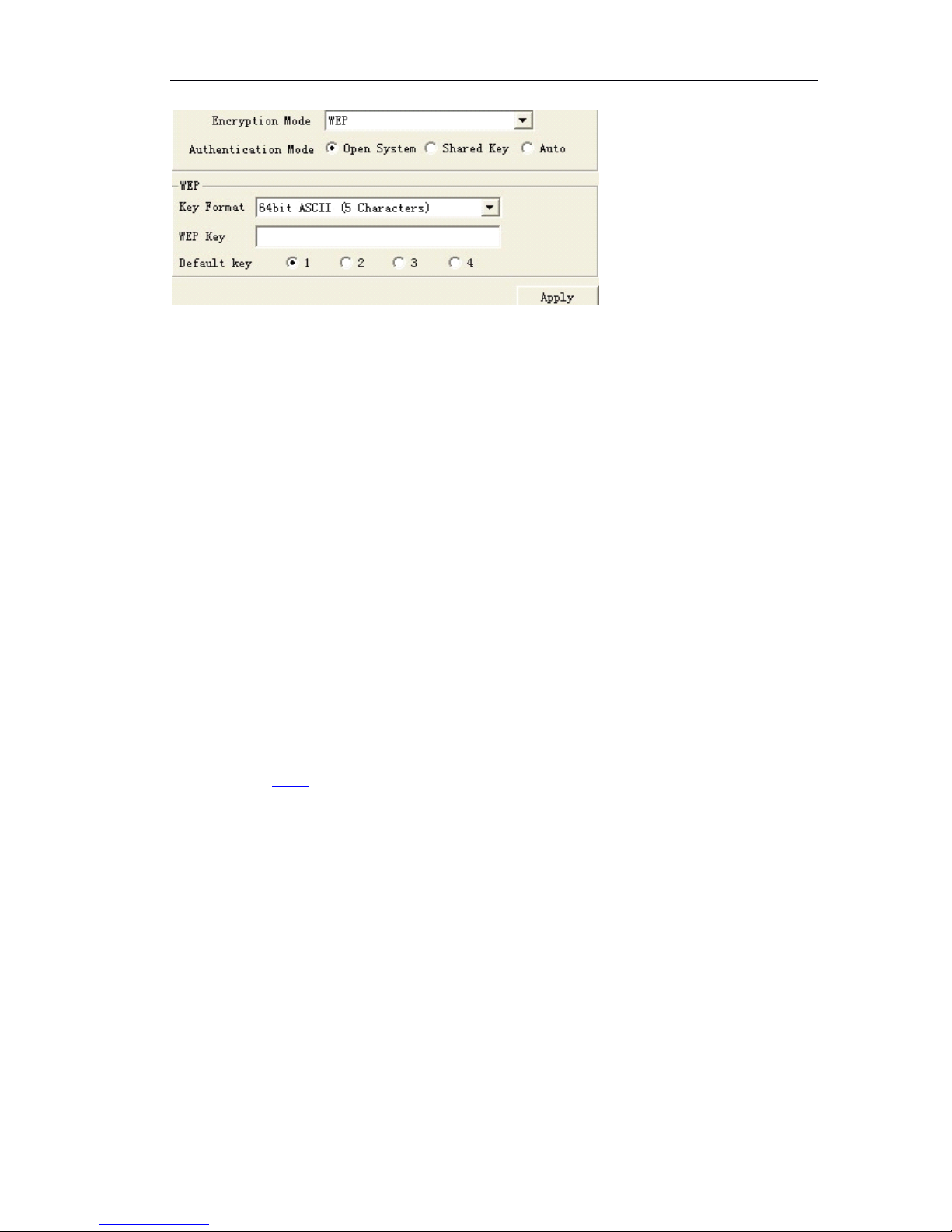
『 Authentication Mode 』 : Choose one of the following modes. The default setting is
“ Open ”
Open
Open
Open
Open : Communicates the key across the Network.
Shared
Shared
Shared
Shared key
key
key
key : Allows communication only with other devices with identical WEP settings.
『 Key Format 』 :The administrator can set the key length to 64 bits. Set the format to
Hexadecimal or ASCII.
HEX
HEX
HEX
HEX : digits consists of numbers 0-9 and the letters A-F
ASCII
ASCII
ASCII
ASCII is the code for representing English letters as numbers from 0-128 except “ ,<,>
and the space character which are reserved.
64 bit key length: 10 Hex digits or 5 characters
Note
Note
Note
Note :
1 The Gateway of wireless network can ’ t be same as the Gateway of wired
network.
2 After wireless configurations are completed, click Apply and reboot the IP
camera.
3 Some invalid settings may cause the system to fail to respond. Change the
configuration settings only if necessary and consult with your network supervisor
or experienced users for correct settings. Once the system has lost contact,
please refer 5.5.1 to for reset the restore procedures.
5.3.6
5.3.6
5.3.6
5.3.6 3G
3G
3G
3G setting
setting
setting
setting (Only
(Only
(Only
(Only for
for
for
for 3G
3G
3G
3G IP
IP
IP
IP Camera
Camera
Camera
Camera models)
models)
models)
models)
Before set the 3G network parameters, make sure you insert SIM card or USIM card into
3G IP Cameras.
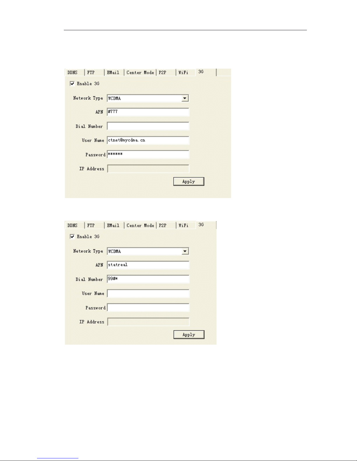
(1) 『 Enable 3G 』 Open this function to make IP camera transmission over 3G network.
(2) 『 Network type 』 Select the corresponded 3G network type. Most North Canada
support EVDO (CDMA2000). And most European countries and asian countries support
WCDMA (UMTS). TD-SCDMA is available in China. Please ask it from your local ISP.
(3) 『 APN 』 Input APN . Please ask it from your local ISP.
(4) 『 Dial Number 』 Dial number of 3G network.
(5) 『 User name 』 user name of 3G network.
(6) 『 Password 』 password of 3G network.
Page 34
Page 34 of 87
Click
『 Apply
』
to save changes. After successful dial-up 3G network, you can see the IP
address.
(WCDMA User in China, dynamic 3G IP address)
(WCDMA user in Israel, static 3G IP address)
Page 35
Page 35 of 87
If
If
If
If your
your
your
your get
get
get
get dynamic
dynamic
dynamic
dynamic 3G
3G
3G
3G IP
IP
IP
IP address,
address,
address,
address, please
please
please
please operate
operate
operate
operate it
it
it
it as
as
as
as follows:
follows:
follows:
follows:
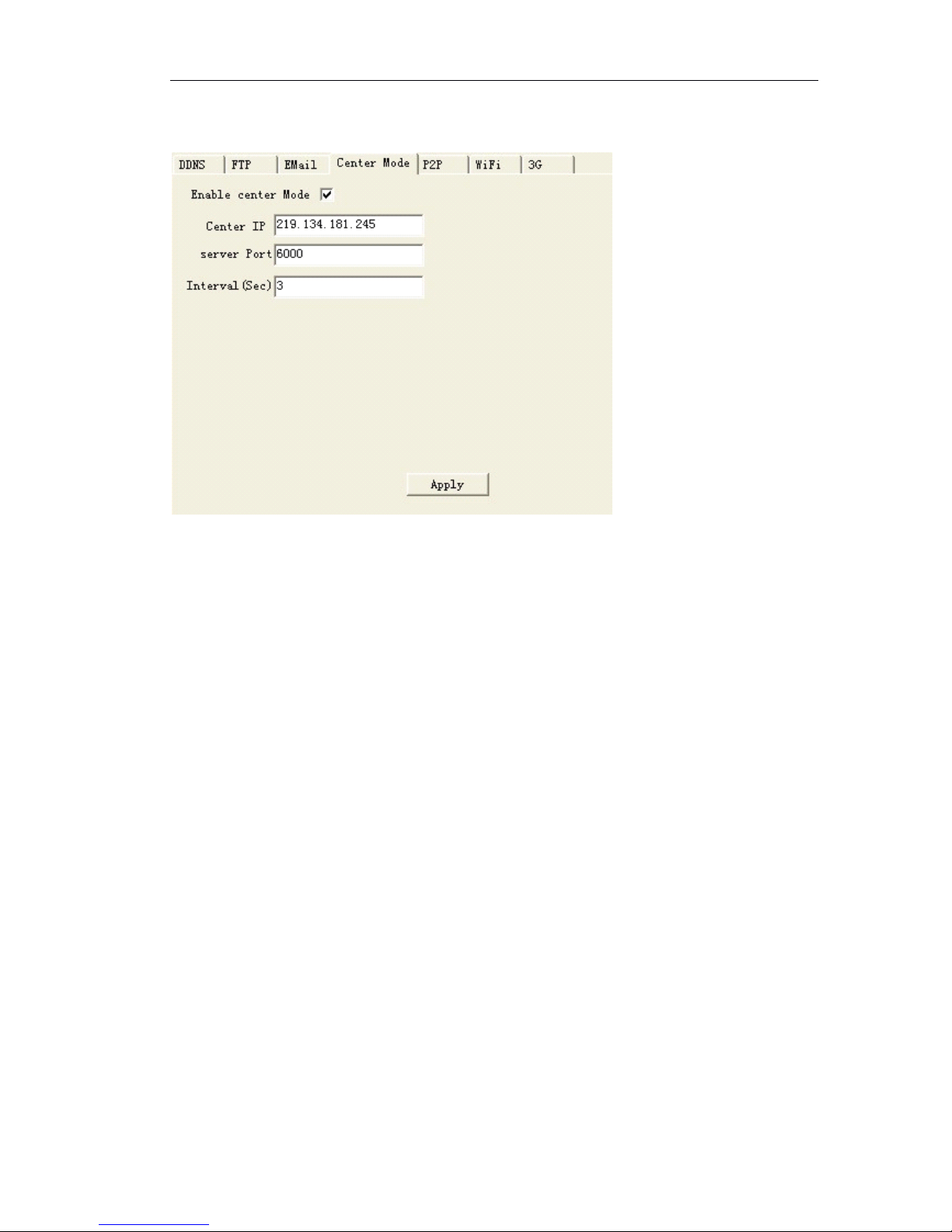
(1) 『 Enable center mode 』 Make CMS can initiatively connect IP camera.
(2) 『 Center IP 』 Input WAN IP address of CMS PC.
(3) 『 Server Port 』 Suggest to set it over than 1024. Make the server port is not occupied .
(4) 『 Interval 』 If dial-up is failed, it automatically dial-up 3G network per 3 seconds.
Note:
Note:
Note:
Note: If CMS PC connects the internet over Router, please map
the
『 Server Port』in th e
router setting.
Page 36
Page 36 of 87
5.4
5.4
5.4
5.4 PTZ
PTZ
PTZ
PTZ setting
setting
setting
setting
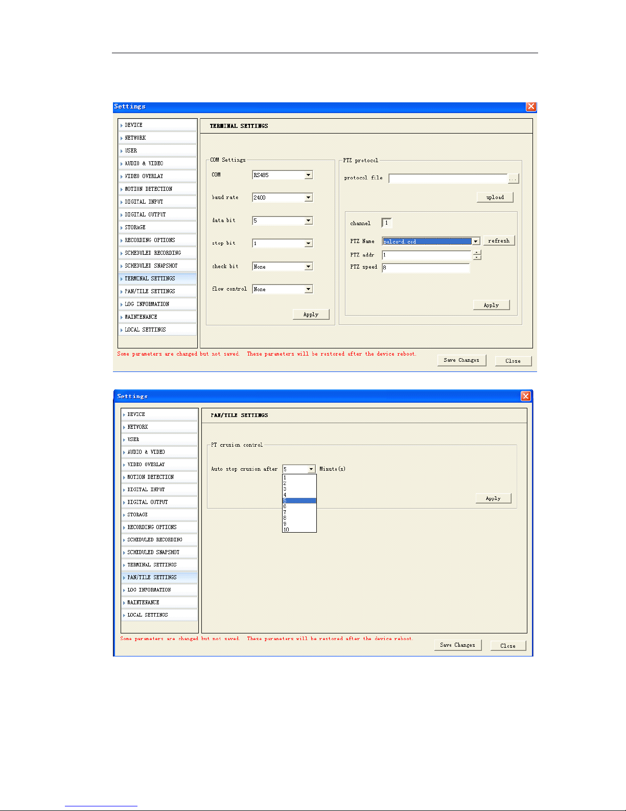
『 Baud rate 』 Input the baud rate of speed dome or pan tilt decoder. Make sure the
baud rate, address and protocol of speed dome or pan tilt decoder is same as video
server.
『 PTZ Add 』 Input the address of the speed dome or pan tilt decoder, generally the
Page 37
Page 37 of 87
address is configurable.
『 PTZ Name』Choose the protocol from the pull down menu, server supports 56 types of
common protocols.
『 Protocol file 』 You can upload your protocol if the protocol you need is not in the pul l
down menu. Server supports transparent transmission, please contact us for further
information about self-defined PTZ protocol.
『 Speed 』 You can set the running speed of the dome here.
『 Apply 』 Click this button when you finished corresponding setting options. Then you
can conveniently control PTZ through our control tool.
5.5
5.5
5.5
5.5 System
System
System
System (version,
(version,
(version,
(version, time
time
time
time configuration,
configuration,
configuration,
configuration, system
system
system
system update,
update,
update,
update, user)
user)
user)
user)
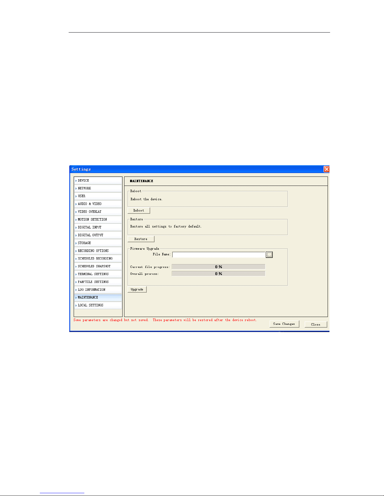
This section introduced system common settings including system upgrade, system
version, system restart, system factory settings restore, shown as following figure:
5.5.1
5.5.1
5.5.1
5.5.1 Firmware
Firmware
Firmware
Firmware upgrade,
upgrade,
upgrade,
upgrade, restore,
restore,
restore,
restore, reboot
reboot
reboot
reboot
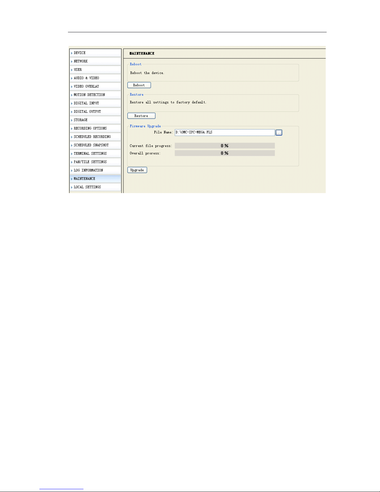
『 Upgrade』Please do not use this function except professionals. Click “ browser ” butto n
to select the update file and press enter.
Page 38
Page 38 of 87
Then click “ Upgrade ”,click “ Ok ” button in a dialog box.
The system will start the upgrade process, a progress bar will indicate upgrade status.
When the upgrade is completed,there will be a status bar showing “ Update success.
The server will restart ” .
『 Restore 』 Load IP camera ’ s factory default settings except network settings and
password.
『 Reboot』Click “ reboot ” button, the IP camera will restart. The action LED indicator will
go off to indicate that the device is rebooting. After around 20-30 seconds, the action
LED will light up again to indicate that the reboot is completed.
5.5.2
5.5.2
5.5.2
5.5.2 Time
Time
Time
Time setting
setting
setting
setting
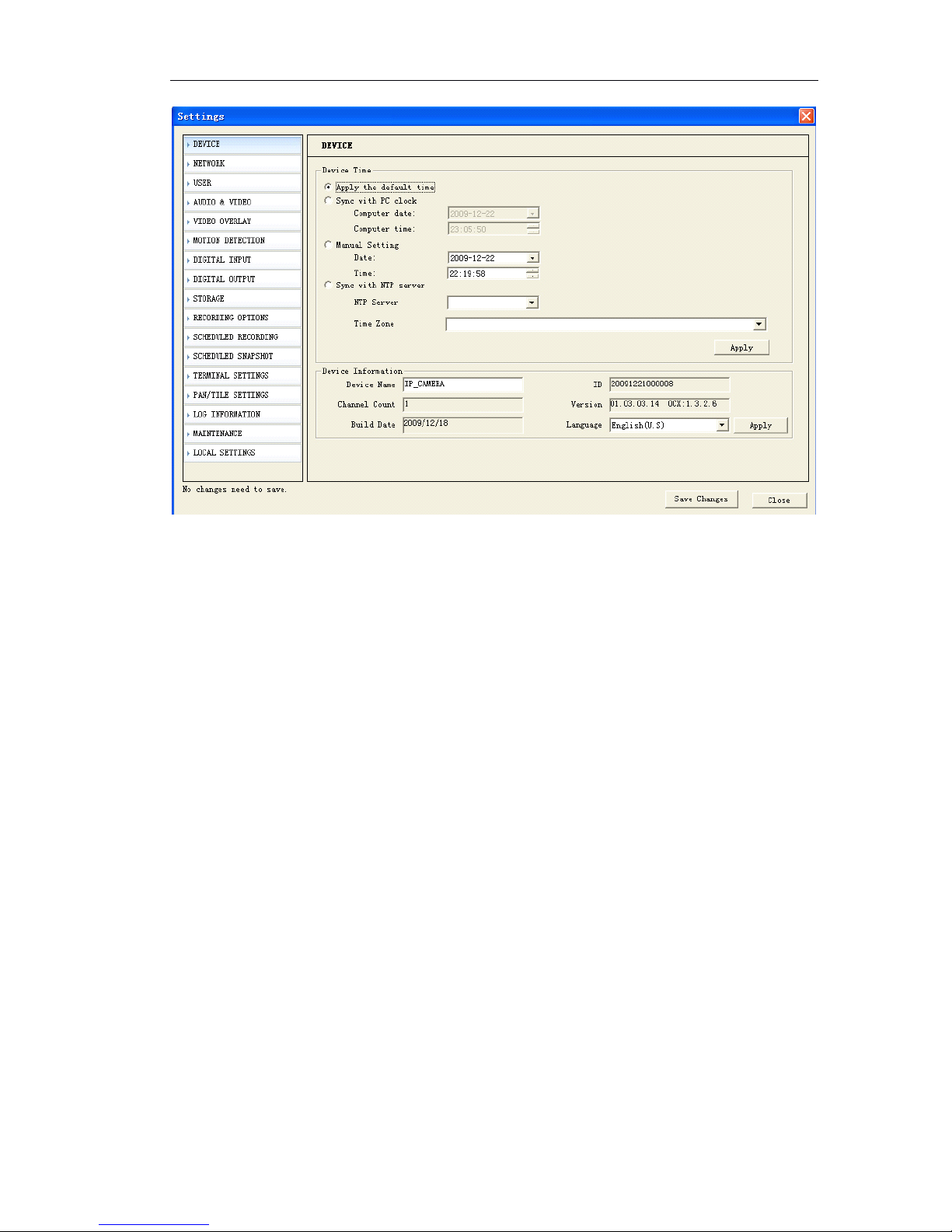
This section tells you how to setup IP camera ’ s date and time settings.
Click the 『 Device
』
on
the
『 Setup
』
page. The time setting page is displayed as belo w
Page 39
Page 39 of 87
『 Sync with PC Clock 』 Select this option to synchronize the date and time of the IP
camera with the local computer.
『 Manual setting 』 The administrator can enter the date and time manually . Note that
the date and time format are YYYY/MM/DD and HH:MM:SS.
『 Sync with NTP Server 』 NTP function enables this video to synchronize its time setting
with a NTP Server. You can use this function to make sure all your IP camera ’ s time is
the same.
『 NTP Server 』 : Assign the IP address or domain name of the time-server. Leaving the
text box blank connects the IP camera to the default time servers.
『 Time zone 』 Select time zone offset for local settings.
『 Apply 』 Click “ apply ” to save the parameter into the server ’ s flash, unless system will
use the former settings after a restart.
5.5.3
5.5.3
5.5.3
5.5.3 Device
Device
Device
Device information
information
information
information
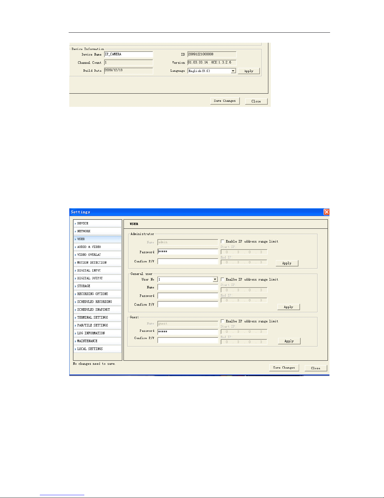
It shows the firmware version.
Support English, Korea, traditional Chinese and simplified Chinese
Page 40
Page 40 of 87
5.5.4
5.5.4
5.5.4
5.5.4 user
user
user
user management
management
management
management
S etup the account names and their respective passwords. There are 1 administrator
account, 10 general user accounts and 1 guest account allowed.
Administrator account allows the users to watch the live view and modify all settings.
Genera l user account allow the users to watch the live view, playback, control the
pan tilt zoom
,
can ’ t change settings.
Guest account only allows watching the live view.
『 Enable IP Address range limit』Clicking “√” on “□” means enable this option. Input th e
start IP address and end IP address. Only enabled IP address can login the IP camera,
otherwise the login will be forbade.
E.g.: If you set Start IP address is 192.168.188.25
End IP address is 192.168.188.29
Page 41

Page 41 of 87
That means the Remote PC which IP address is 192.168.188.25, 192.168.188.26,
192.168.188.27, 192.168.188.28, 192.168.188.29 can view and control the IP camera.
5.6
5.6
5.6
5.6 Alarm
Alarm
Alarm
Alarm (sensor
(sensor
(sensor
(sensor alarm,
alarm,
alarm,
alarm, motion
motion
motion
motion detection)
detection)
detection)
detection)
This section describes the Network Camera alarm parameter setting and the
responding when Network Cameras received an alarm
5.6.1
5.6.1
5.6.1
5.6.1 sensor
sensor
sensor
sensor alarm
alarm
alarm
alarm
After the sensor alarm service is enabled, when the sensor input alarm happened,
Network Camera will perform following actions:
Capture JPG image and upload to client
Trigger alarm output
Snapshot email notification
Snapshot FTP notification
Alarm record
Send alarm information to client or trigger the unconnected client connection and
video opening
Alarm type
Combined
action
Trigger event
Alarm
Video
motion
alarm
Can
combine
camera
output
1Images capture and upload to
client, 2. FTP notification
3 email notification 4 Record
5 trigger output
Client
configurable
and save in log
Sensor input
alarm
Can
combine
camera
output
1Images capture and upload to
client, 2. FTP notification
3 email notification 4 Record
5 trigger output
Client
configurable
and save in log
Page 42
Page 42 of 87
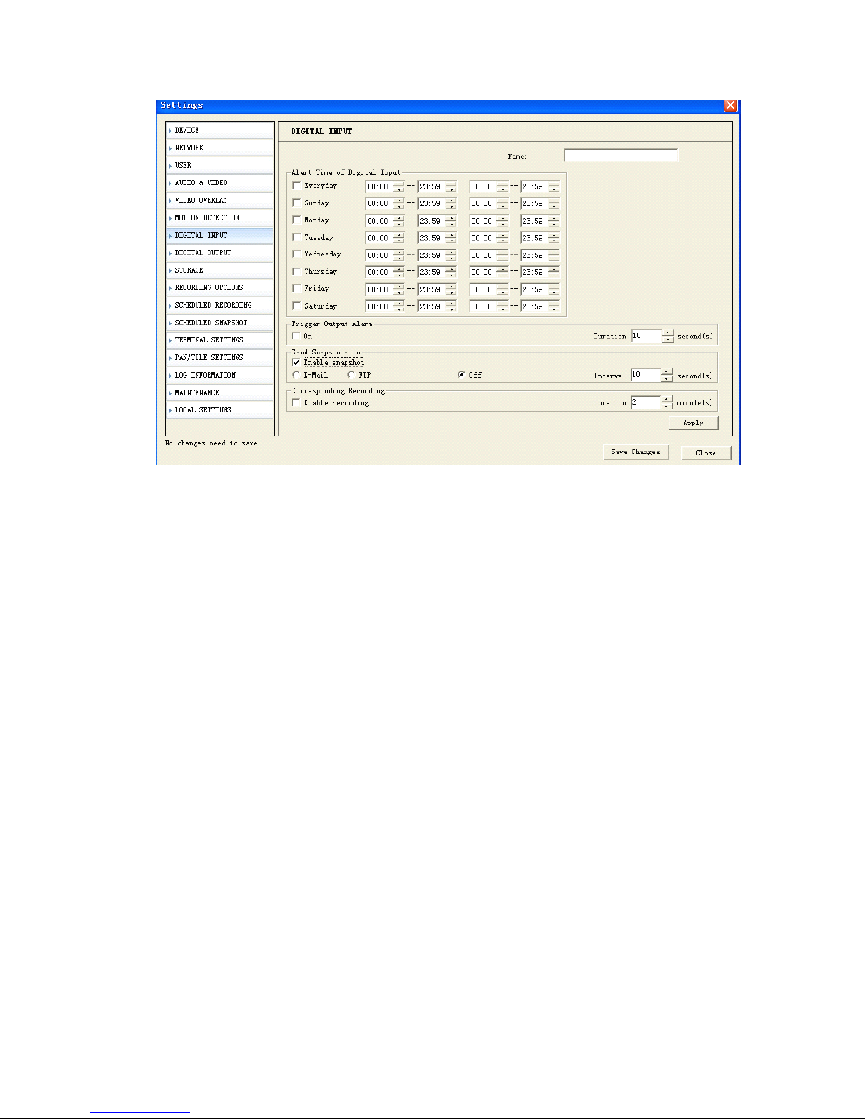
『 Name 』 The description of a sensor for easy remembering, for example “ entrance ”
,
“ switch room ”
『 Alarm Time of digital input』Input value to detect sensor trigger events in specific tim e
according to real conditions.
『 Duration 』 The sensor output will be canceled after this time
『 Enable Snapshot』When the sensor trigger events happened, system will send alar m
JPG image by email or FTP automatically. The client must be specified firstly and set
『 EMAIL 』 and 『 FTP 』 in 『 Setup 』 -- 『 Network 』 .
『 Trigger Output Alarm
』
System provide 1 channel on-off value for user to connect wit h
bells, lights, beepers etc. When sensor trigger event happens, system will output on-off
value to attached devices.
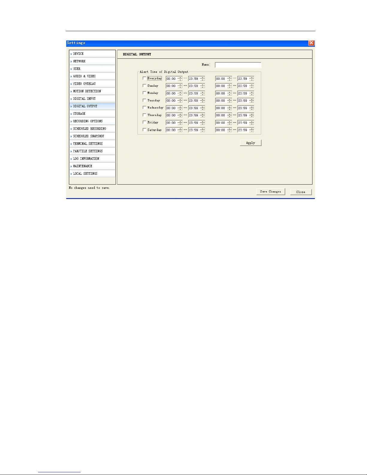
Alarm Out Setup:
Page 43
Page 43 of 87
The function of alarm output is to automatically trigger specific sensor output on-off
value to trigger alarm devices such as beepers.
5.6.2
5.6.2
5.6.2
5.6.2 motion
motion
motion
motion detection
detection
detection
detection
After the video motion alarm function is enabled, when there are motions in the image
at specific time and district, the Network Camera will perform alarm operation such as
JPG image capture or sensor output combination and send alarm message to client
ac cording to the action setting. Client will deal with the alarm according to the local
setting. Video motion alarm information including server name, IP, alarm type, and
time will be saved into log for future inquiry.
In the “ Motion Detection ” setting shown as below figure.
Page 44
Page 44 of 87
『 Duration 』 The sensor output will be canceled after this time
『 Enable Snapshot』When the sensor trigger events happened, system will send alar m
JPG image by email or FTP automatically. The client must be specified firstly and set
『 EMAIL 』 and 『 FTP 』 in 『 Setup 』 -- 『 Network 』 .
『 Trigger Output Alarm
』
System provide 1 channel on-off value for user to connect wit h
bells, lights, beepers etc. When sensor trigger event happens, system will output on-off
value to attached devices.
『 Detection area』To set the image dynamic detection zone (each channel of image is
divided into a matrix with 9 rows and 11 lines. There are 99 zones can be set), zones out
of set zones will not perform the dynamic detection task. Red zones mean “ they are
image dynamic detection zones ” . You can draw the zones with mouse.
『 Sensitive 』 The sensitivity of motion detection, you can define it according to the real
applications..
Setting skill
You can set the detection sensitivity as a higher value to avoid the false alarm causing
by small object motions.
You can set sensitivity as a higher value to avoid the frequent alarm at environment
where object motions frequently happen.
Only extreme accurate motion alarm settings need lower sensitivity value. High
sensitivity value is recommended for all other situations.
Page 45
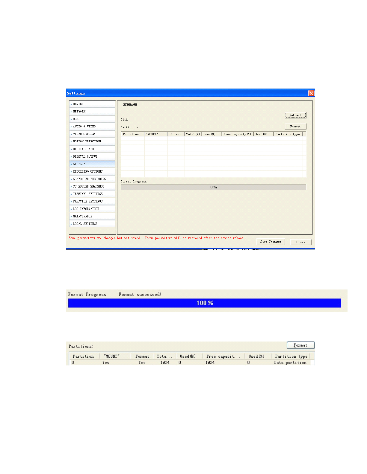
Page 45 of 87
5.7
5.7
5.7
5.7 SD
SD
SD
SD Card
Card
Card
Card Record
Record
Record
Record
Before you set the SD card record function, make sure you already insert the SD card.
5.7.1
5.7.1
5.7.1
5.7.1 Format
Format
Format
Format SD
SD
SD
SD card
card
card
card
『 Format 』 Format SD card. After you click Format, it pops up a dialogue “ Are you sure
to format to format the Disk ” . Click “ OK ” to format it.
After successes format, it shows information as follows:
5.7.2
5.7.2
5.7.2
5.7.2 Schedule
Schedule
Schedule
Schedule record
record
record
record on
on
on
on SD
SD
SD
SD card
card
card
card
If 24 hours every day to record, you can click 『 Everyday 』 Start from 00:00 to 23:59.
If snapshot when holidays, you can click 『 Saturday
』 『
Sunday』start from 00:00 to 23: 59.
If snapshot when work off, you can click 『 Monday 』 『 Tuesday
』 『
Wednesday
』
『 Thursday
』 『
Friday 』 start from 12:00-14:00 18:00-23:59
Page 46
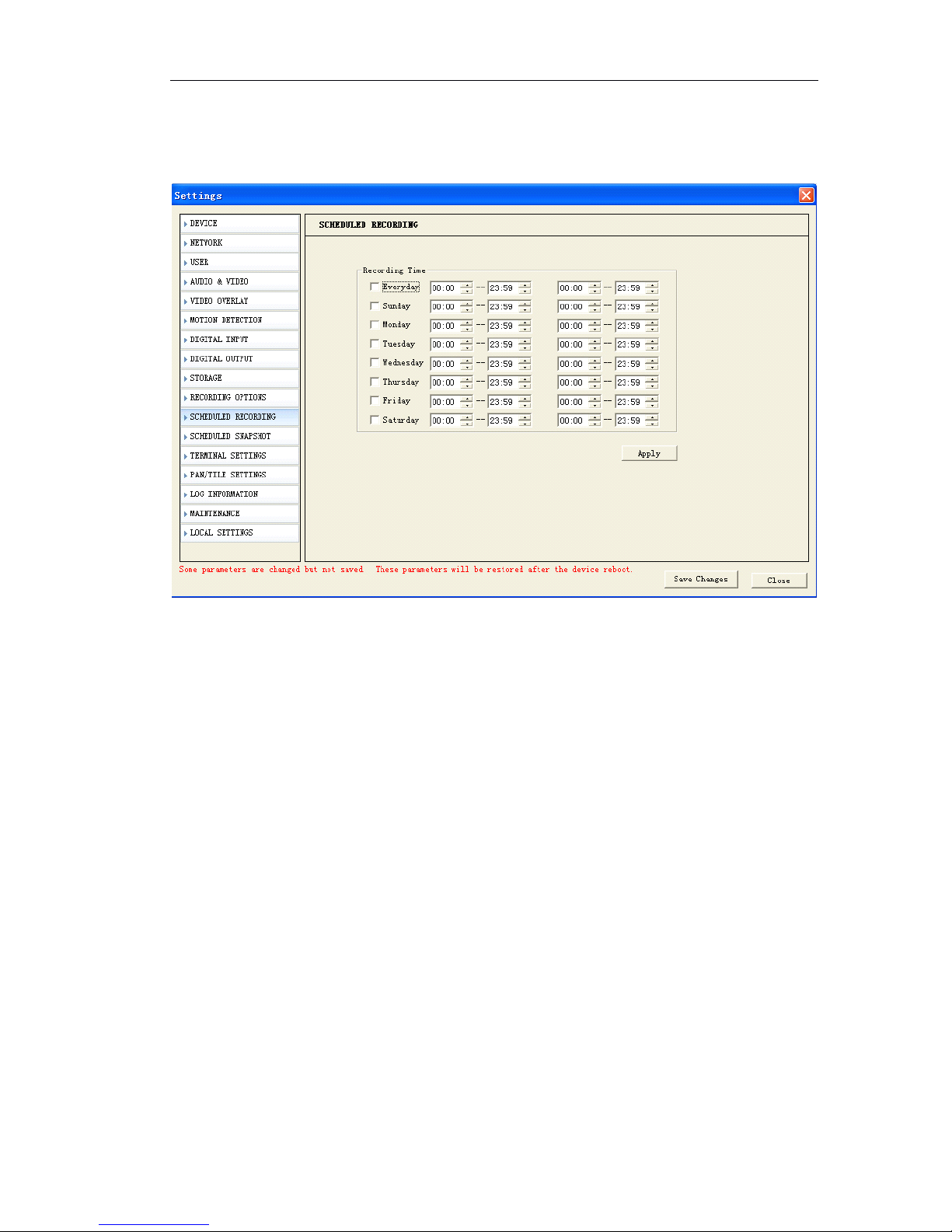
Page 46 of 87
Click 『 Apply 』 to save the changes, click 『 Save changes 』 to save in Flash.
5.7.3
5.7.3
5.7.3
5.7.3 Schedule
Schedule
Schedule
Schedule snapshot
snapshot
snapshot
snapshot on
on
on
on SD
SD
SD
SD card
card
card
card
If you would like to get more video information but limited SD card space. Snapshot
can save one photo on SD card per your schedule, per second, per 10 seconds, per
minute, per 20 minutes, per hour or per day. Meanwhile, you can define your time
schedule.
If 24 hours every day to snapshot, you can click 『 Everyday 』 Start from 00:00 to 23:59.
If snapshot when holidays, you can click 『 Saturday
』 『
Sunday』start from 00:00 to 23: 59.
If snapshot when work off, you can click 『 Monday 』 『 Tuesday
』 『
Wednesday
』
『 Thursday
』 『
Friday 』 start from 12:00-14:00 18:00-23:59
Page 47
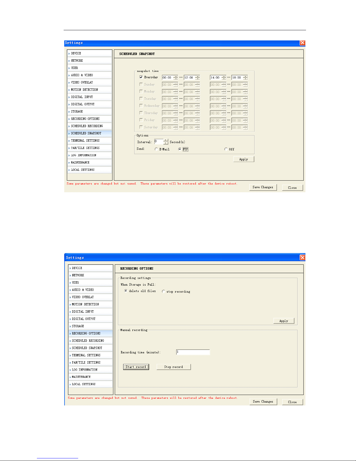
Page 47 of 87
『 Interval 』 Set interval time to send snapshot. You can set it from 1 second to 99,999
seconds.
Click 『 Apply 』 to save the changes, click 『 Save changes 』 to save in Flash.
5.7.4
5.7.4
5.7.4
5.7.4 Overwrite
Overwrite
Overwrite
Overwrite setting
setting
setting
setting
『 Delete old files 』 When SD card is full, it automatically delete old files
Page 48
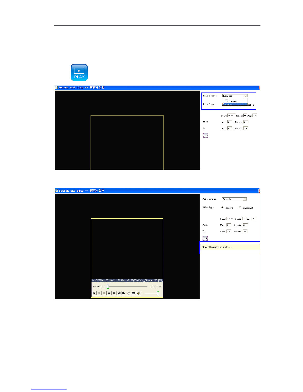
Page 48 of 87
『 Stop recording 』 When SD card is full, stop record.
5.7.4
5.7.4
5.7.4
5.7.4 Play
Play
Play
Play the
the
the
the record
record
record
record file
file
file
file of
of
of
of SD
SD
SD
SD card
card
card
card
Click
,
it pops up the following dialogue
『 File Source』Choose Remote from drop-down menu to play the record file or snapsh ot
of SD card.
『 File Type 』 Search files by Record or Snapshot.
Set start time/date and end time/date.
Click Search button.
Page 49
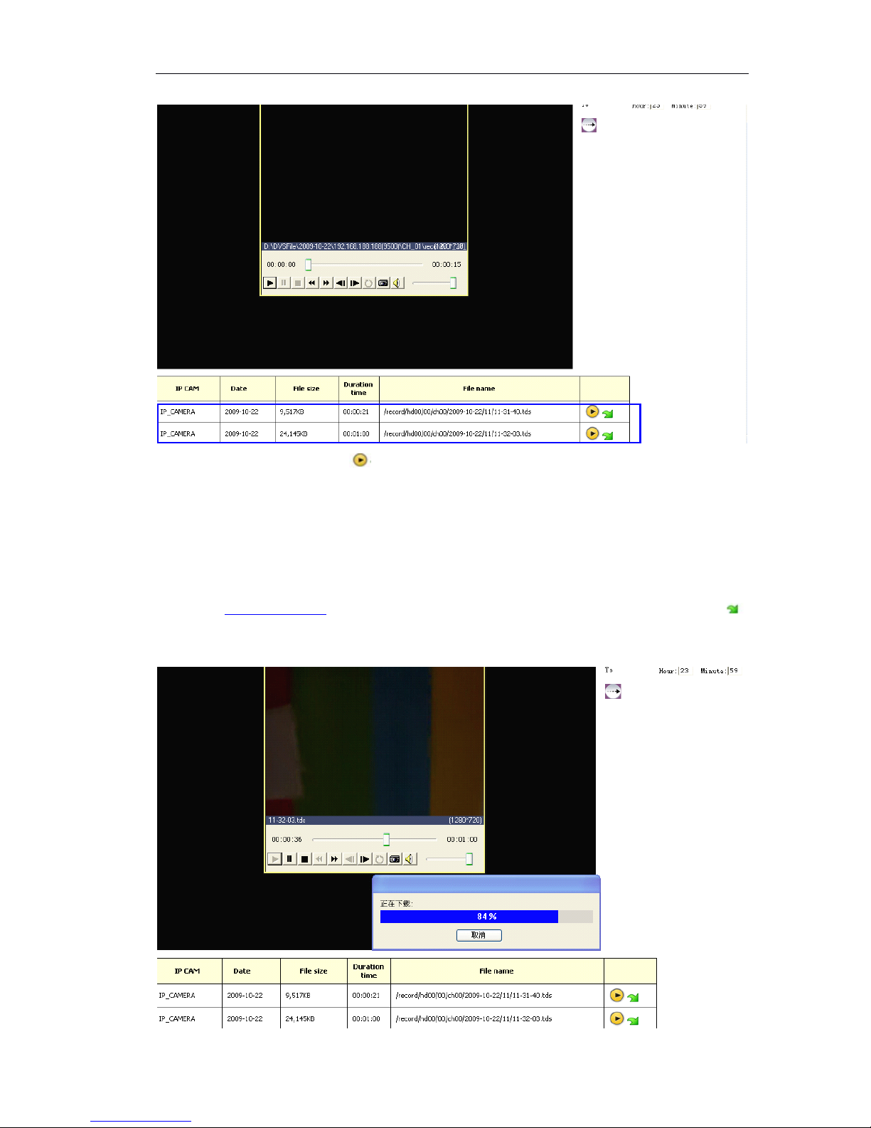
Page 49 of 87
It shows record file list. Click to play it
5.7.5
5.7.5
5.7.5
5.7.5 Download
Download
Download
Download the
the
the
the record
record
record
record files
files
files
files or
or
or
or snapshots
snapshots
snapshots
snapshots of
of
of
of SD
SD
SD
SD card
card
card
card
After you search the files,choose the video files which want to backup, then click
to download.
Page 50
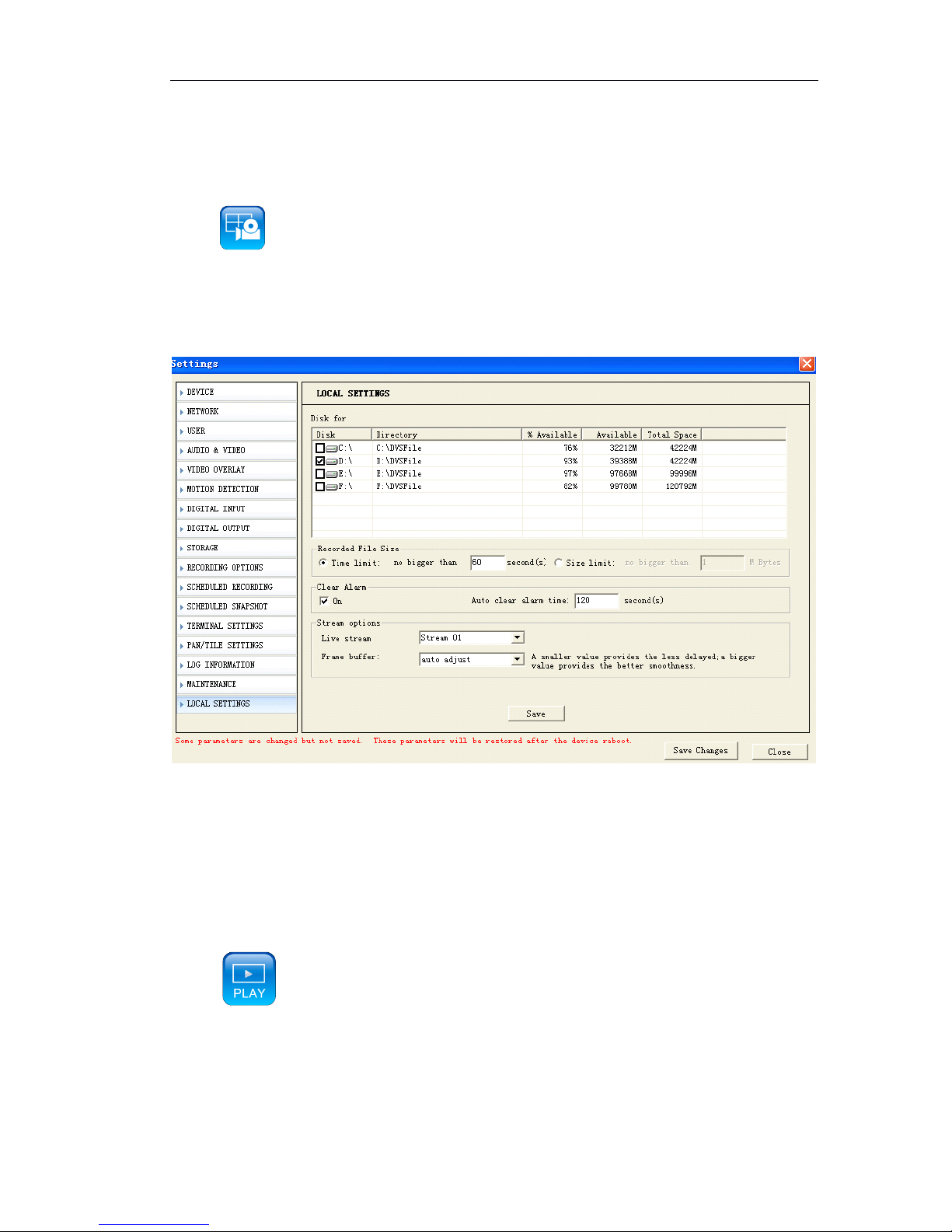
Page 50 of 87
5.8
5.8
5.8
5.8 Manual
Manual
Manual
Manual Record
Record
Record
Record over
over
over
over IE
IE
IE
IE
Click to start manual record, and re-click to stop manual record.
5.8.1
5.8.1
5.8.1
5.8.1 Local
Local
Local
Local record
record
record
record file
file
file
file path
path
path
path
Choose the hard disk drive for local record and snapshot.
The files will be saved under Hard disk drive/DVSFile
『 Time limit』Pack record file by time, default is package one record file per one minut e.
1-9999999 seconds can set .
『 Size limit 』 Pack record file by file size. 1-999999999 Mega Bytes can be set.
5.8.2
5.8.2
5.8.2
5.8.2 Play
Play
Play
Play Local
Local
Local
Local record
record
record
record file
file
file
file
Click
,
it pops up the following dialogue
Page 51
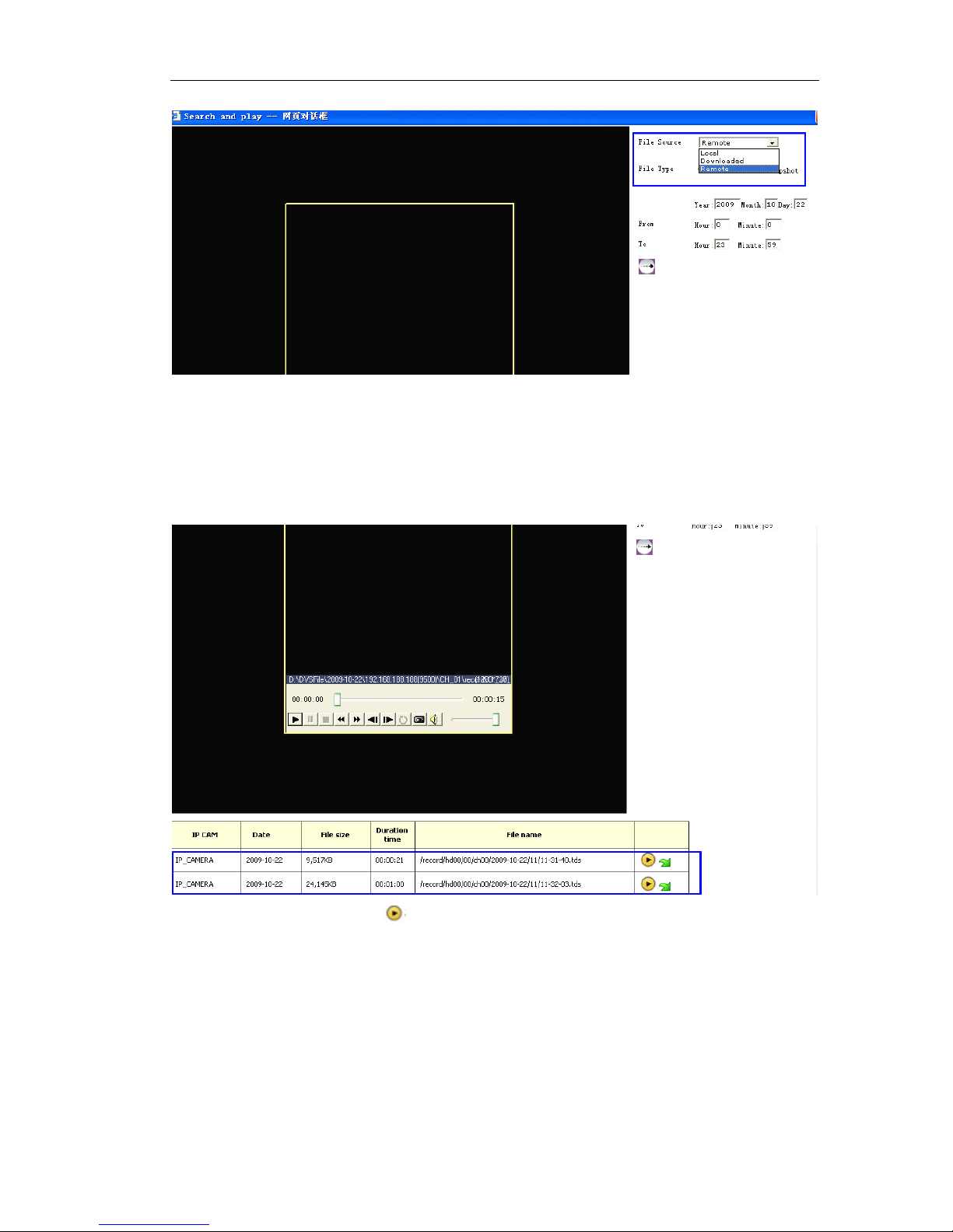
Page 51 of 87
『 File Source
』
Choose Local
Local
Local
Local from drop-down menu to play the record file in hard disk of
PC.
『 File Type 』 Search files by Record or Snapshot.
Set start time/date and end time/date.
Click Search button.
It shows record file list. Click to play it
Page 52
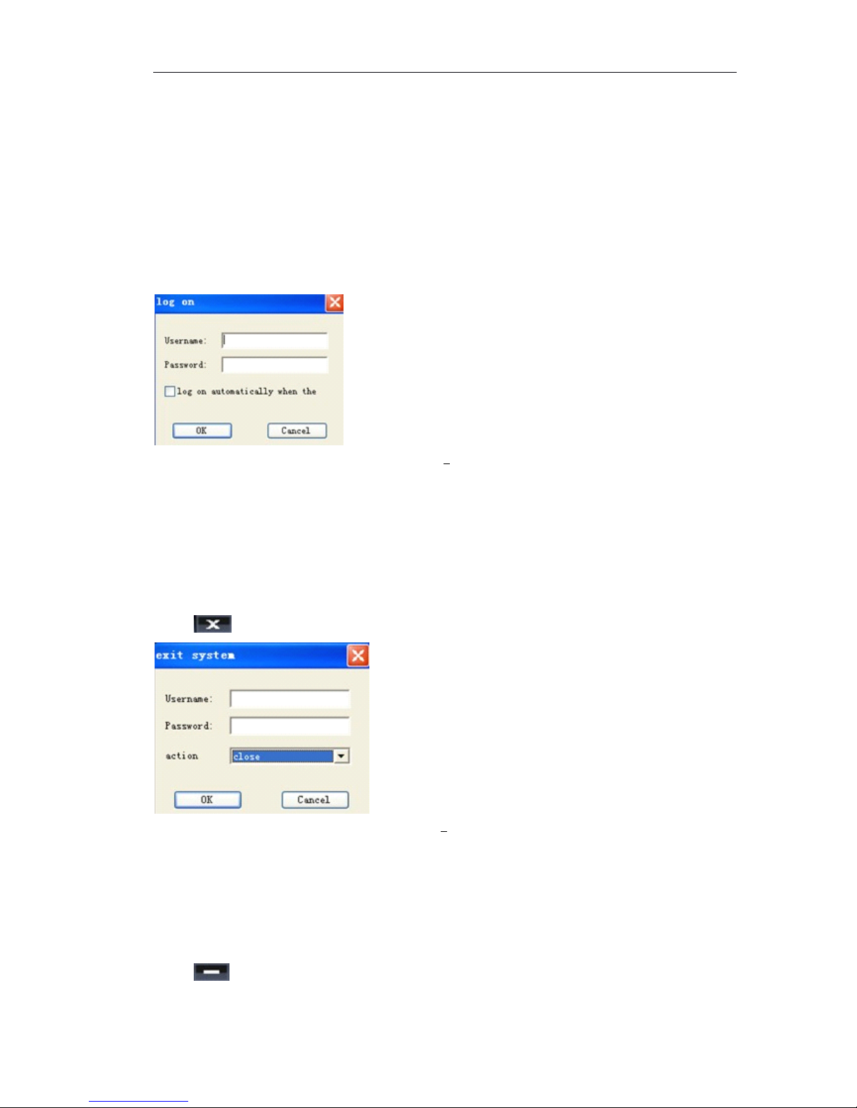
Page 52 of 87
6
6
6
6 How
How
How
How to
to
to
to use
use
use
use Management
Management
Management
Management software?
software?
software?
software?
6.1
6.1
6.1
6.1 System
System
System
System login
login
login
login and
and
and
and logout
logout
logout
logout
6.1.1
6.1.1
6.1.1
6.1.1 System
System
System
System Login
Login
Login
Login
In Windows operation system, run “ CMS ” in “ start ” ” program ” ” CMS ” menu, the
user login window will pop up
Figure 0 1 Login
Default user name is admin, password is null.
Click “ ok ” to enter the main menu
Main menu consists of remote view, function button, servers list and status display.
6.1.2
6.1.2
6.1.2
6.1.2 Log
Log
Log
Log out
out
out
out system
system
system
system
Click button in main menu, a dialogue box will pop up:
Figure 错误!未找到引用源。
错误!未找到引用源。
错误!未找到引用源。
错误!未找到引用源。 2 Logout input dialogue box
Input username and password and click ok to logout system.
Close: Close the CMS
Log off: Exist to use current user and change to another user to login.
6.1.3
6.1.3
6.1.3
6.1.3 Minimize
Minimize
Minimize
Minimize system
system
system
system
Click to minimize the CMS.
Page 53
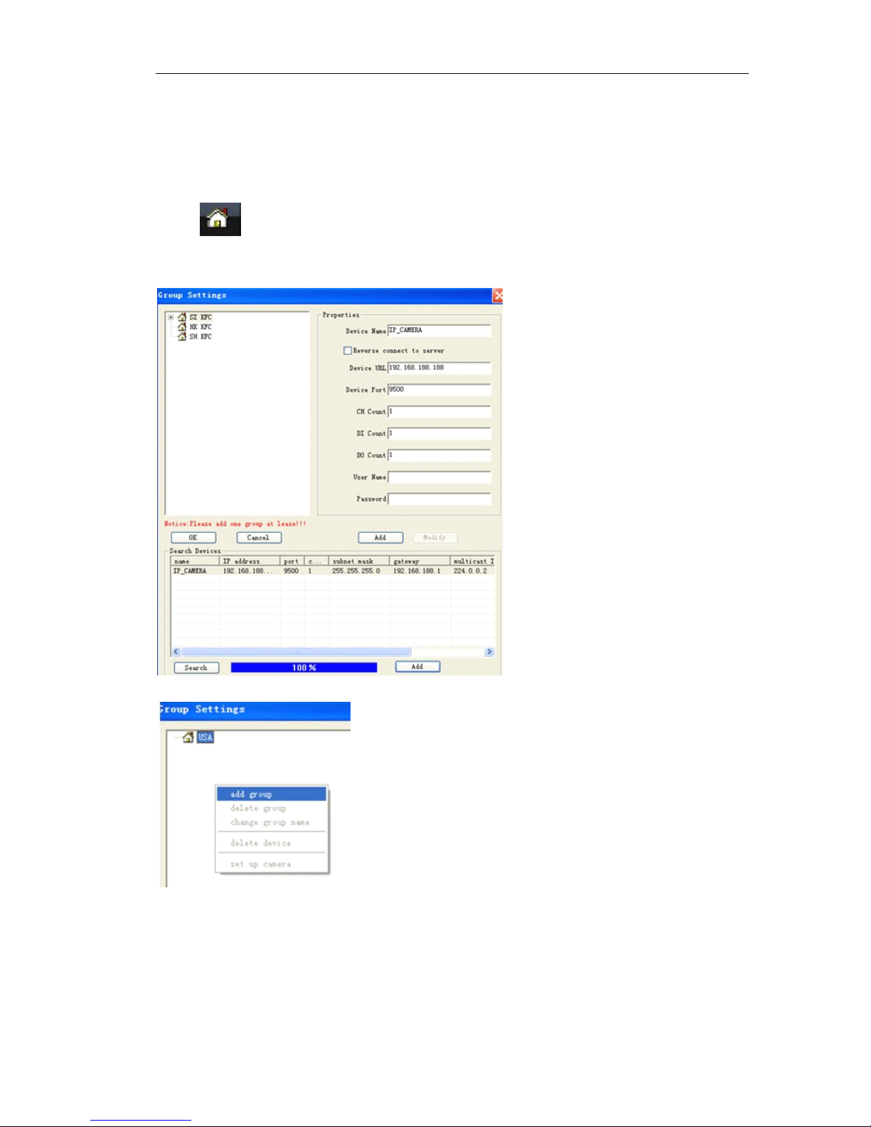
Page 53 of 87
6.2
6.2
6.2
6.2 System
System
System
System setting
setting
setting
setting
6.2.1
6.2.1
6.2.1
6.2.1 Server
Server
Server
Server management
management
management
management (Add
(Add
(Add
(Add IP
IP
IP
IP camera)
camera)
camera)
camera)
Server management will add group and add IP camera in the group settings.
Click on bottom of main menu or Click right mouse button on main menu,
choose “ Group Settings ” and then a window will pop up,
(1)
(1)
(1)
(1) Add
Add
Add
Add groups
groups
groups
groups
Click right mouse to add ‘ Groups ’,CMS supports up to 100 Groups.
Define the group name. E.g. Shang Hai Bank of China, Shenzhen Bank of China, New
York Bank of China.
(2)
(2)
(2)
(2) Add
Add
Add
Add IP
IP
IP
IP cameras
cameras
cameras
cameras by
by
by
by Search.
Search.
Search.
Search.
Page 54
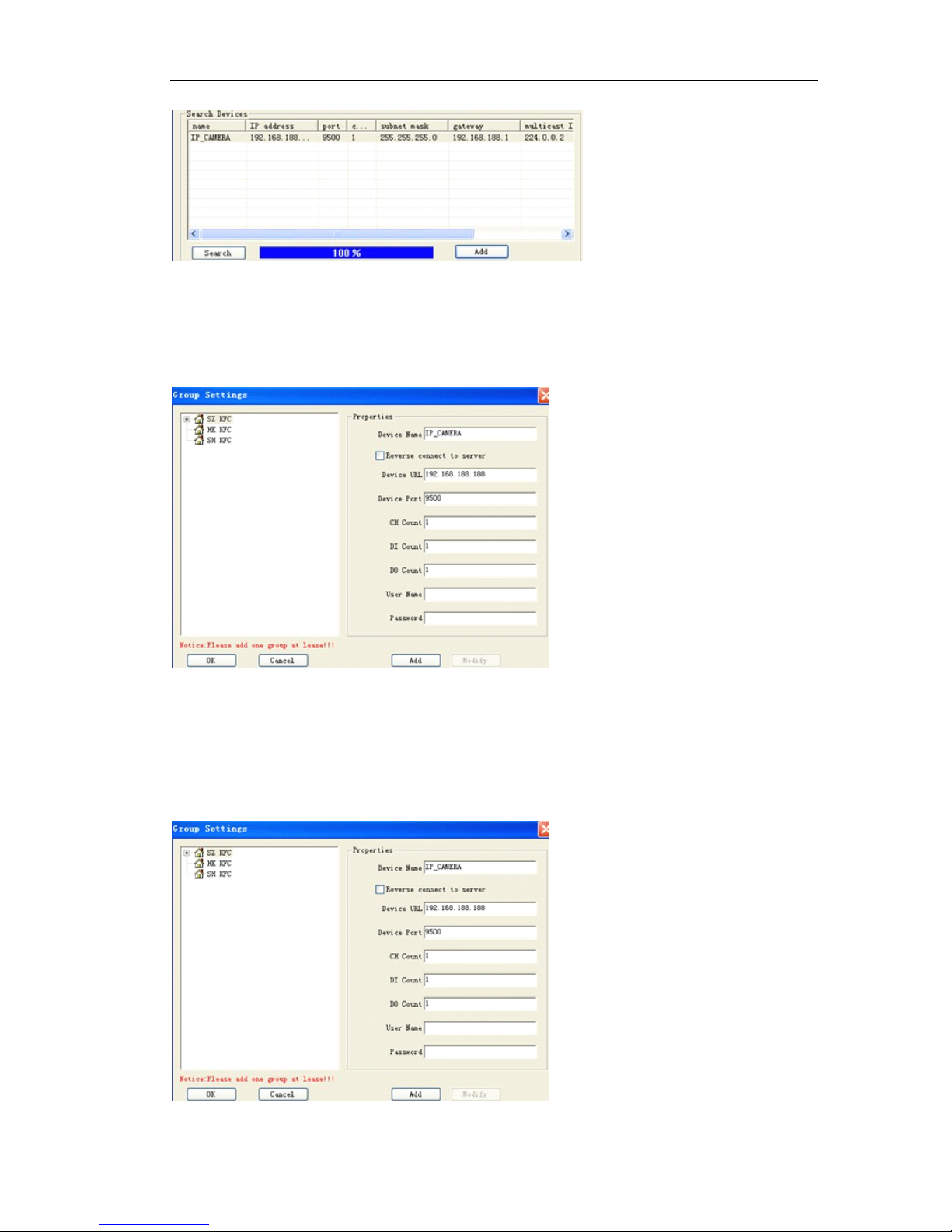
Page 54 of 87
Click 『 Search 』 to find IP cameras.
Click IP addresses which you want to connect.
And click 『 Add 』 to add IP cameras in the groups.
Then in 『 Properties』,
input the user name and password of IP Camera. (Default settin g
is admin for user name and password). Click 『 Add 』 to add it in the selected group.
(3)
(3)
(3)
(3) Add
Add
Add
Add IP
IP
IP
IP cameras
cameras
cameras
cameras by
by
by
by manually.
manually.
manually.
manually.
Input the parameter of server which you manage, input IP camera ’ s IP address, local
device name, port, additional information. Input user name and password of IP
camera. (Default setting is admin for user name and password of IP camera).
Page 55
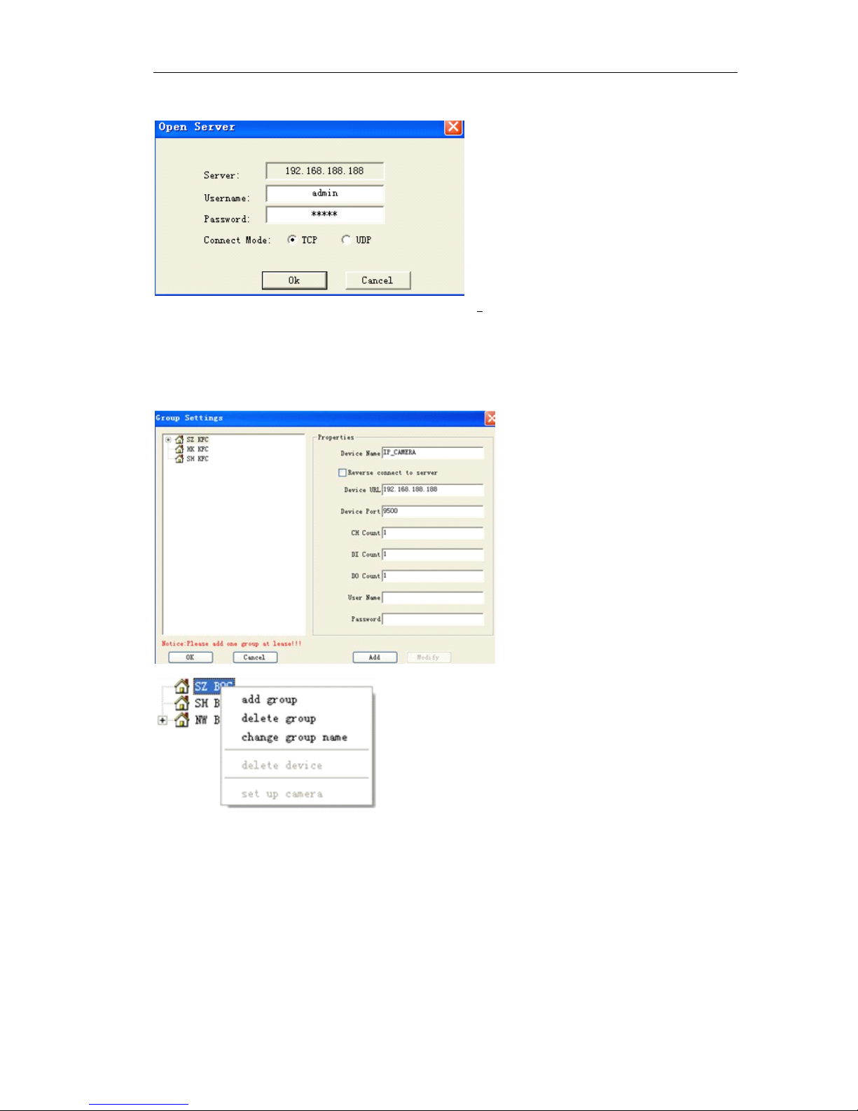
Page 55 of 87
Figure 错误!未找到引用源。
错误!未找到引用源。
错误!未找到引用源。
错误!未找到引用源。 3 login the server
( 4
4
4
4 ) Delete
Delete
Delete
Delete group
group
group
group and
and
and
and change
change
change
change group
group
group
group name
name
name
name
In the 『 Group Settings 』
,
right click mouse on selected IP camera which you want to
change the name or delete to choose 『 Delete group 』 or 『 Change group name 』
(5)Modify
(5)Modify
(5)Modify
(5)Modify parameters
parameters
parameters
parameters of
of
of
of IP
IP
IP
IP camera
camera
camera
camera
Server modification: select IP camera and click the 『 modify 』
Page 56
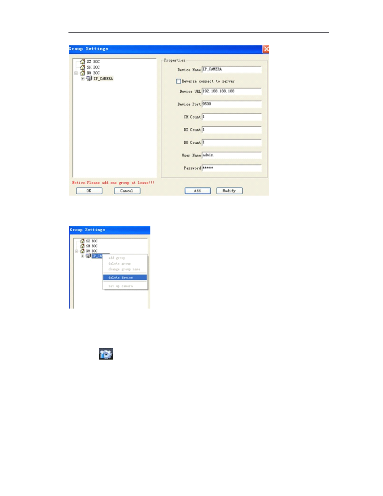
Page 56 of 87
(6)
(6)
(6)
(6) Delete
Delete
Delete
Delete IP
IP
IP
IP camera
camera
camera
camera
Right click mouse on the selected IP camera which want to delete, click 『 Delete
Device 』
6.2.2
6.2.2
6.2.2
6.2.2 User
User
User
User management
management
management
management
Click the button in the bottom of main menu to pop up a local setting window
and enter the normal setting attribute page, please refer to the figure:
Page 57
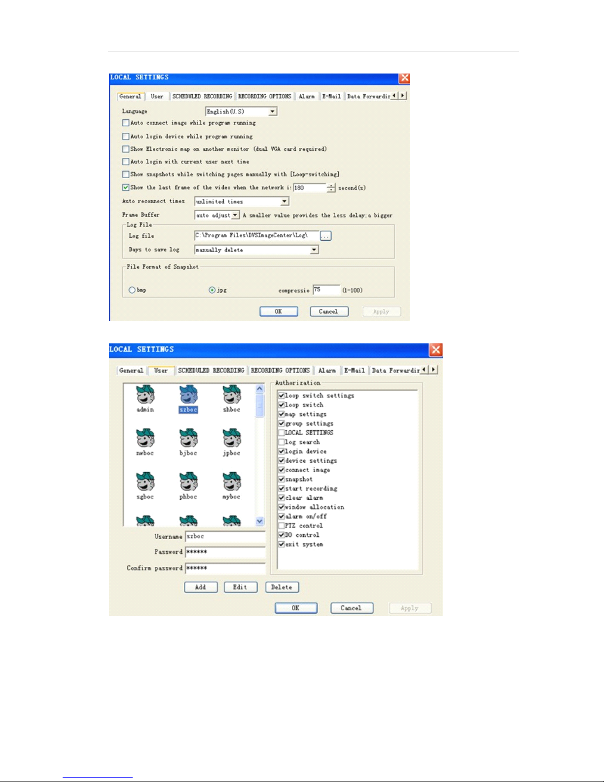
Page 57 of 87
Click 『 user 』
,
it switches to the following figure
Input user name, password and confirm password.
Set the authorities and click 『 Add 』 .
You can add up to 100 users for different authorities.
The authority of each user can be defined.
Administrator ’ s authority is that can manage and configure all parameters.
Page 58
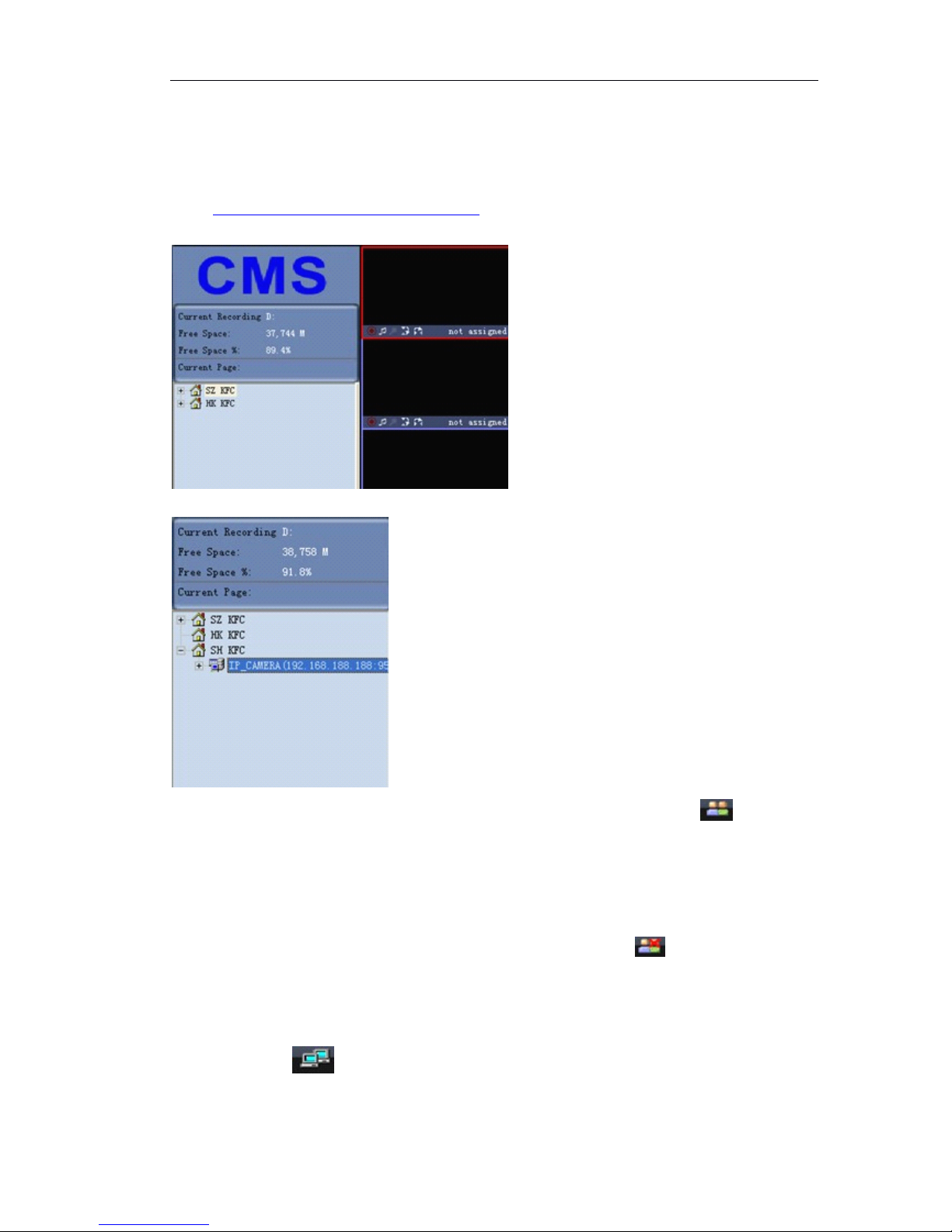
Page 58 of 87
6.3
6.3
6.3
6.3 IP
IP
IP
IP Camera
Camera
Camera
Camera live
live
live
live view
view
view
view
6.3.1
6.3.1
6.3.1
6.3.1 Log
Log
Log
Log in
in
in
in and
and
and
and log
log
log
log off
off
off
off IP
IP
IP
IP camera
camera
camera
camera
After add IP camera in the group setting , on the left side of main menu, you can see
the director tree.
Double Click on “ Group Name ”,e.g. “ SH KFC ”,it shows IP cameras as below:
Double Click IP camera or right click mouse to select “ Log on ” or click at bottom
of main menu.
“ Log on ” status: IP camera keeps online on CMS, but no video connection.
Log
Log
Log
Log off
off
off
off IP
IP
IP
IP camera
camera
camera
camera
Select IP camera, right click mouse to select “ Log off ” or click .
6.3.2
6.3.2
6.3.2
6.3.2 Live
Live
Live
Live view
view
view
view IP
IP
IP
IP camera
camera
camera
camera
After log in IP camera, Double click camera01 or right click mouse to select “ Connect
image ” or click at bottom of main menu.
Page 59
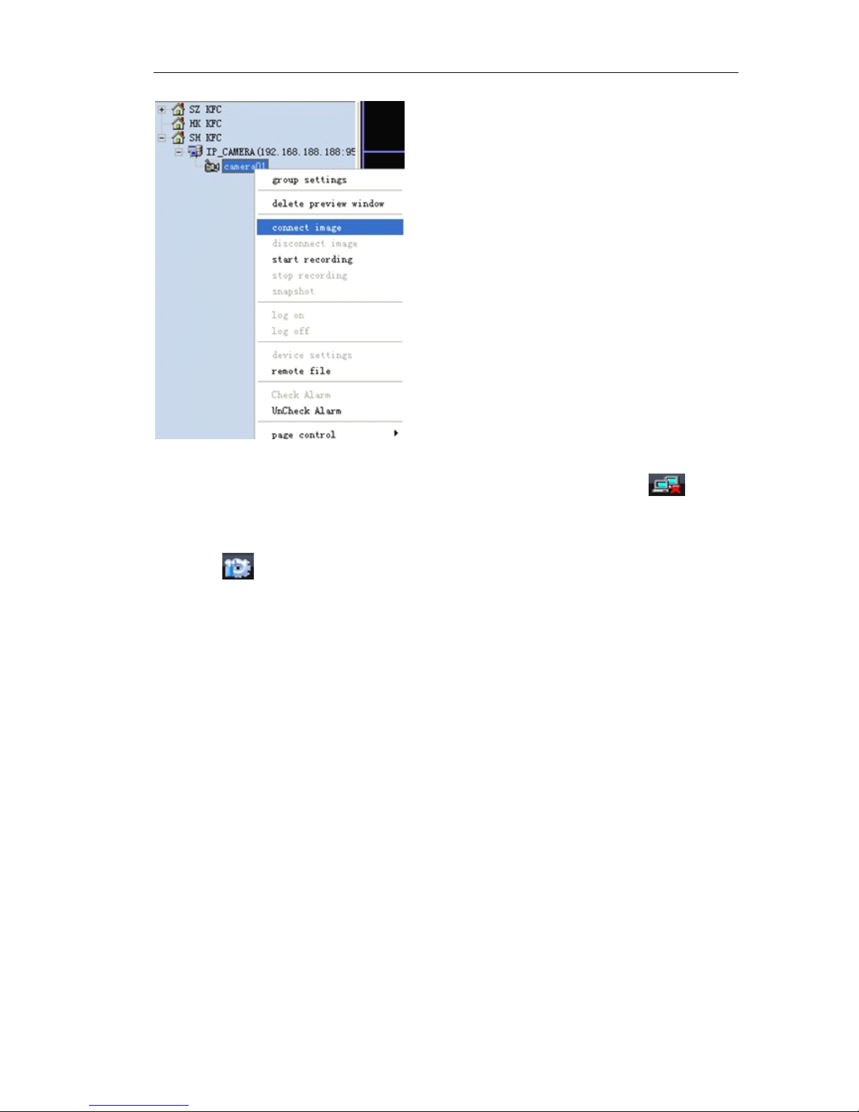
Page 59 of 87
Disconnect
Disconnect
Disconnect
Disconnect Image
Image
Image
Image
Select IP camera, right click mouse to select “ disconnect image ” or click .
6.3.3
6.3.3
6.3.3
6.3.3 Auto
Auto
Auto
Auto log
log
log
log in
in
in
in IP
IP
IP
IP camera
camera
camera
camera and
and
and
and Auto
Auto
Auto
Auto Connect
Connect
Connect
Connect IP
IP
IP
IP camera
camera
camera
camera
Click the button in the bottom of main menu to pop up a local setting window
and enter the “ General ” attribute page, click “ Auto connect image while program
running ” and “ Auto login device while program running ”
『 Auto reconnect times 』 When fail to log in IP camera, support automatically re-
connect. 0, 25, 75,100 and unlimited times can be defined.
Page 60
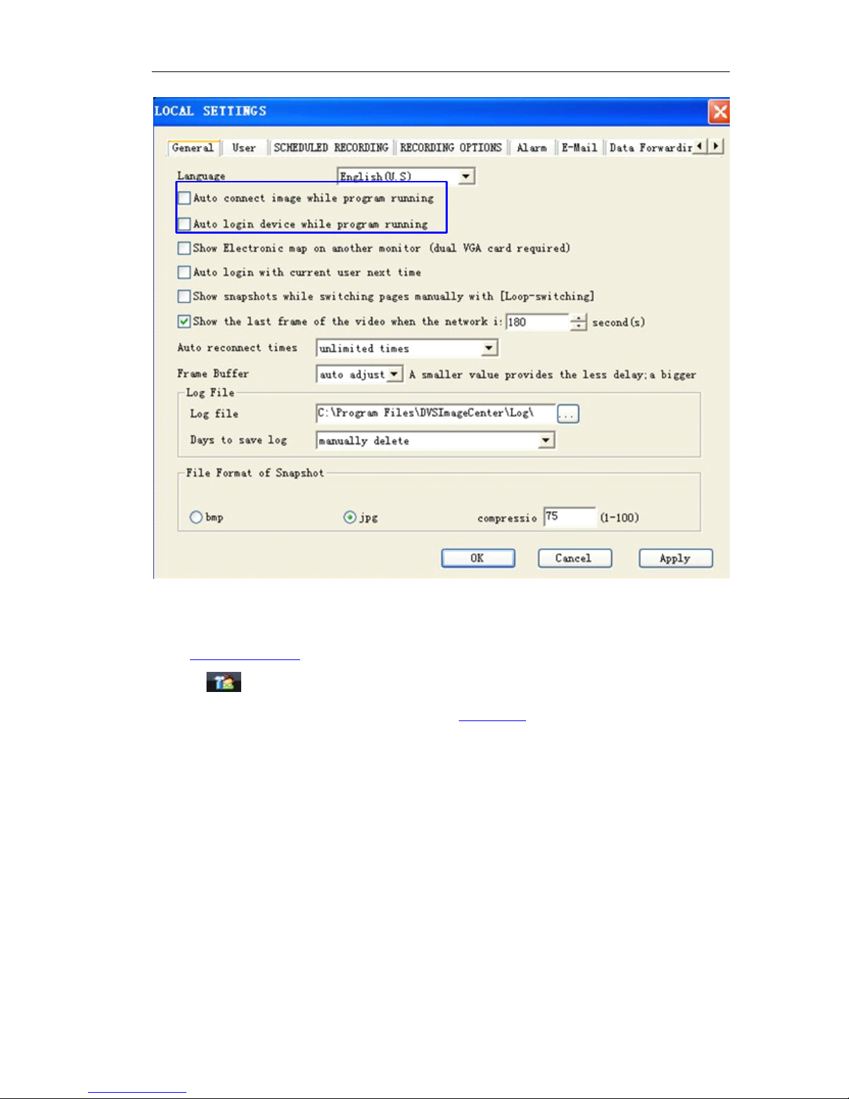
Page 60 of 87
6.4
6.4
6.4
6.4 Remote
Remote
Remote
Remote setup
setup
setup
setup IP
IP
IP
IP Camera
Camera
Camera
Camera
After log in IP camera,select IP camera, right click mouse to choose “ device setting ”
or click to remote setup IP camera or right click
For the IP camera configurations, please refer Chapter 5 .
6.5
6.5
6.5
6.5 Multi-view
Multi-view
Multi-view
Multi-view IP
IP
IP
IP camera
camera
camera
camera and
and
and
and control
control
control
control
The system can provide manage and configure 200channels IP cameras. You can live
view 36channels in one screen. CMS supports loop switch.
6.5.1
6.5.1
6.5.1
6.5.1 Loop
Loop
Loop
Loop switch
switch
switch
switch
Right click mouse on the IP camera to select “ Loop switching settings ”,it pops up the
following figure:
Page 61
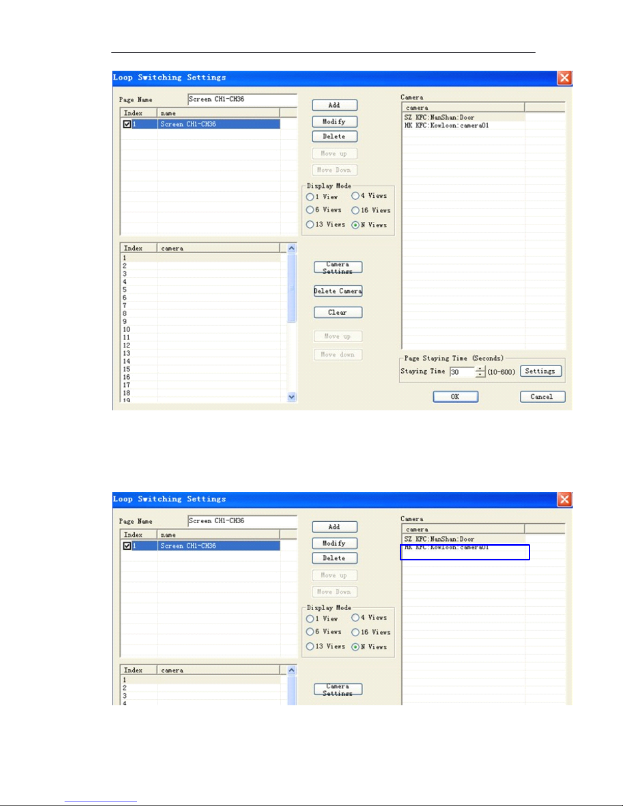
Page 61 of 87
(1) Add page name: after input the name and click “ Add ”
(2) Select the display mode: 1/4/6/16/13/36 Views, if one screen shows 36ch IP camera ,
click “ N ” views.
(3) Add IP camera: double click IP camera from right side “ Camera list ” .
(4)The IP Camera will be added on the left side as follows
Page 62
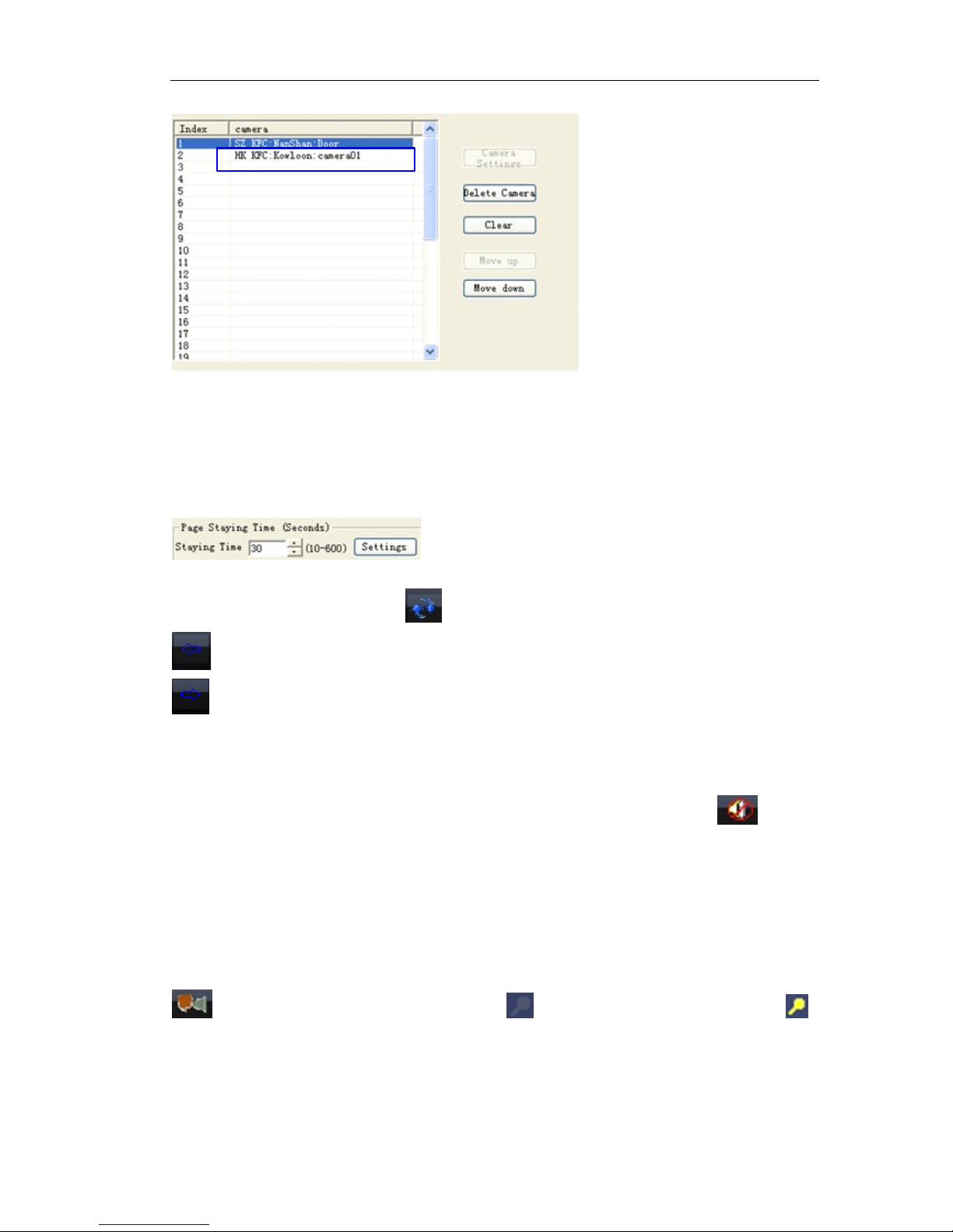
Page 62 of 87
(5) Repeat the third steps until all Ip cameras are added.
(6) You can change the display order by “ Move up ” or “ Move down ” button.
(7) Automatically switch page: Users can set interval time between page 1 and page
2. Default settings are 30 seconds.
If more Ip cameras are displayed which are in higher resolution, suggest setting the
longer time.
(8) Click “ OK ” to save changes.
(9) Manually loop switch: Click on the main menu to loop switch.
: Switch to previous screen
: Switch to next screen
6.5.2
6.5.2
6.5.2
6.5.2 Sound
Sound
Sound
Sound play
play
play
play control
control
control
control and
and
and
and two
two
two
two way
way
way
way audio
audio
audio
audio
Open the Network Camera ’ s channel video, select video image, click button
on the below of the main menu to open the audio intercom. Then re-click this button
to close sound.
Note
Note
Note
Note : please make sure the Network Camera has already encoded audio and
connect with audio input before the play.
: talk with IP camera, enable it, the icon on Ip camera video changes to .
Page 63
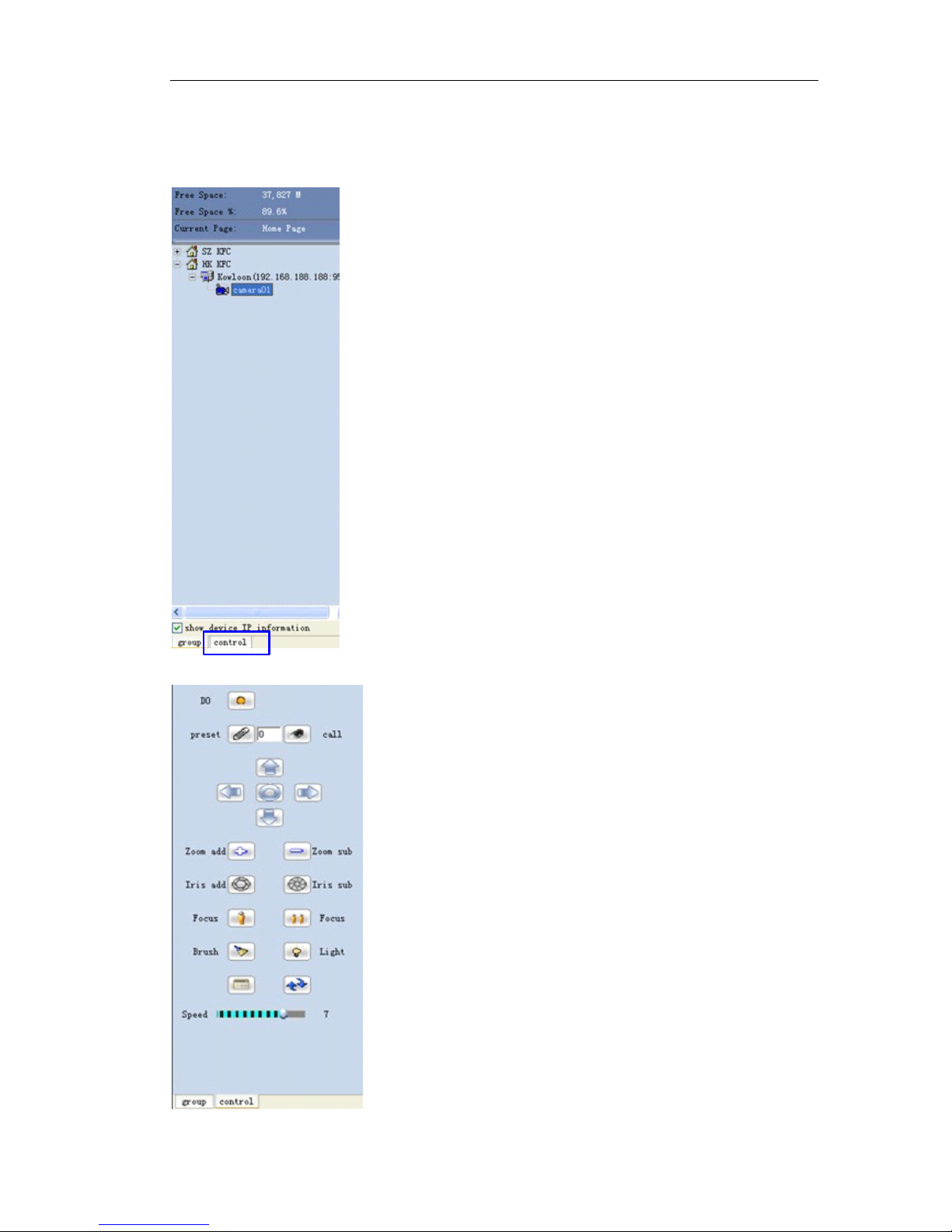
Page 63 of 87
6.5.3
6.5.3
6.5.3
6.5.3 PTZ
PTZ
PTZ
PTZ control
control
control
control
Open the server ’ s channel video, select the video image, there will be a red frame
around the image. Click “ Control ”
Click “ Control ”,it pops up the following figure:
Page 64
Page 64 of 87
: Pan left, right, up and down.
Zoom add: Zoom out
Zoom sub: zoom in
Iris add:
Iris sub:
Note: please check the PTZ setting errors and PTZ device errors if the control failed.
Preset position
Open the Network Camera ’ s channel video and select video image.
Add preset position: preset PTZ to a position and input number in the preset position
input box, click “ preset ” button to complete the setting.
Input number in the preset position input box, click “ call ” to preset the camera.
6.6
6.6
6.6
6.6 Snapshot
Snapshot
Snapshot
Snapshot
6.6.1
6.6.1
6.6.1
6.6.1 How
How
How
How to
to
to
to Snapshot
Snapshot
Snapshot
Snapshot
Users can manually snapshot images while they are viewing video.
Method
Method
Method
Method 1:
1:
1:
1: Select the “ Snapshot ” item from the pop up menu by clicking open video
image with the right mouse button.
Method
Method
Method
Method 2
2
2
2 : Select open video image with left mouse button, and then click
button in main menu with left mouse button.
6.6.2
6.6.2
6.6.2
6.6.2 Search
Search
Search
Search snapshot
snapshot
snapshot
snapshot
Click button in main menu to pop up the player menu, select the “ Image file ”
to view images
Page 65
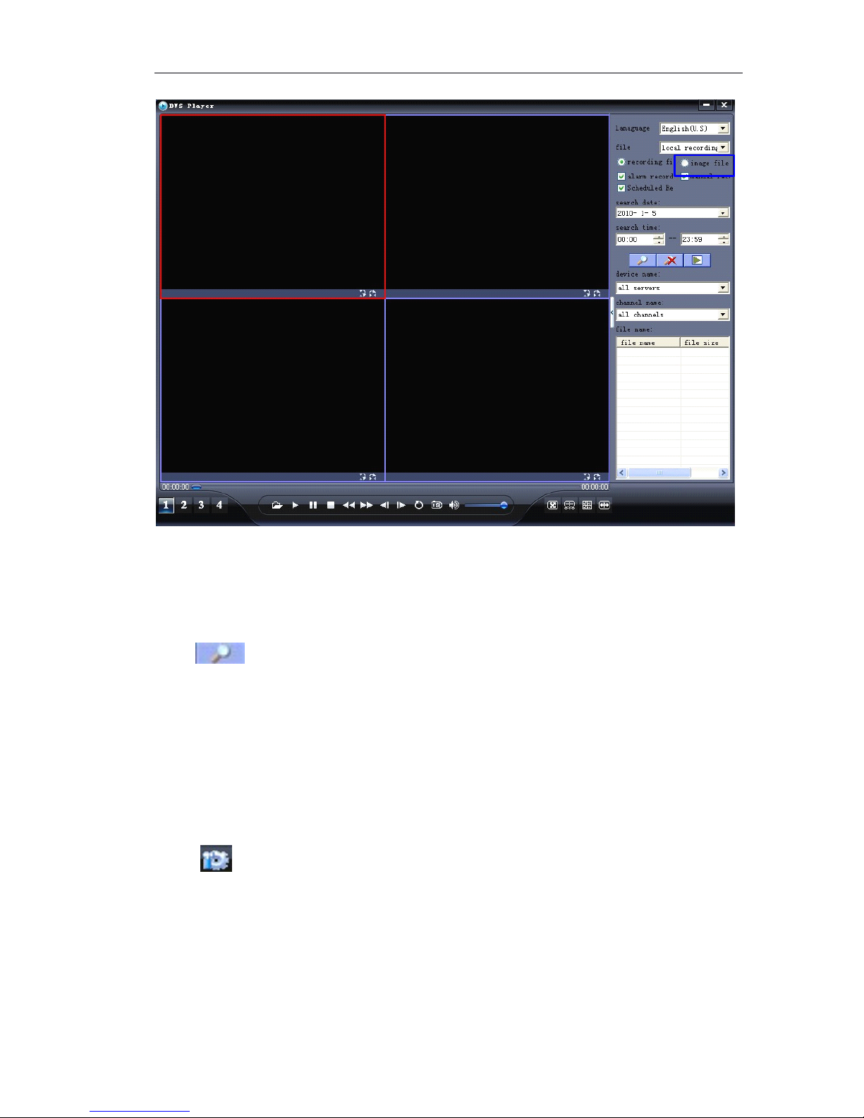
Page 65 of 87
Search
Search
Search
Search path:
path:
path:
path:
Local record: the files are saved in PC.
Remote download: the files are kept in SD card of IP camera.
Search
Search
Search
Search mode
mode
mode
mode : define the search condition, Search by devices and Search by date.
Click to begin search.
6.7
6.7
6.7
6.7 Record
Record
Record
Record
The system supports 7*24 hours record, manual record, alarm record, pre-record,
local/remote record search, and record cover automatically.
6.7.1
6.7.1
6.7.1
6.7.1 General
General
General
General setting
setting
setting
setting (Record
(Record
(Record
(Record path,
path,
path,
path, overwrite,
overwrite,
overwrite,
overwrite, record
record
record
record package)
package)
package)
package)
Setting
Setting
Setting
Setting path:
path:
path:
path:
Click button in main menu to pop up the local setting menu, enter the
“ Recording Options ” attribute page, and choose the storage hard driver in the “ Local
Record Disk ” .
Page 66
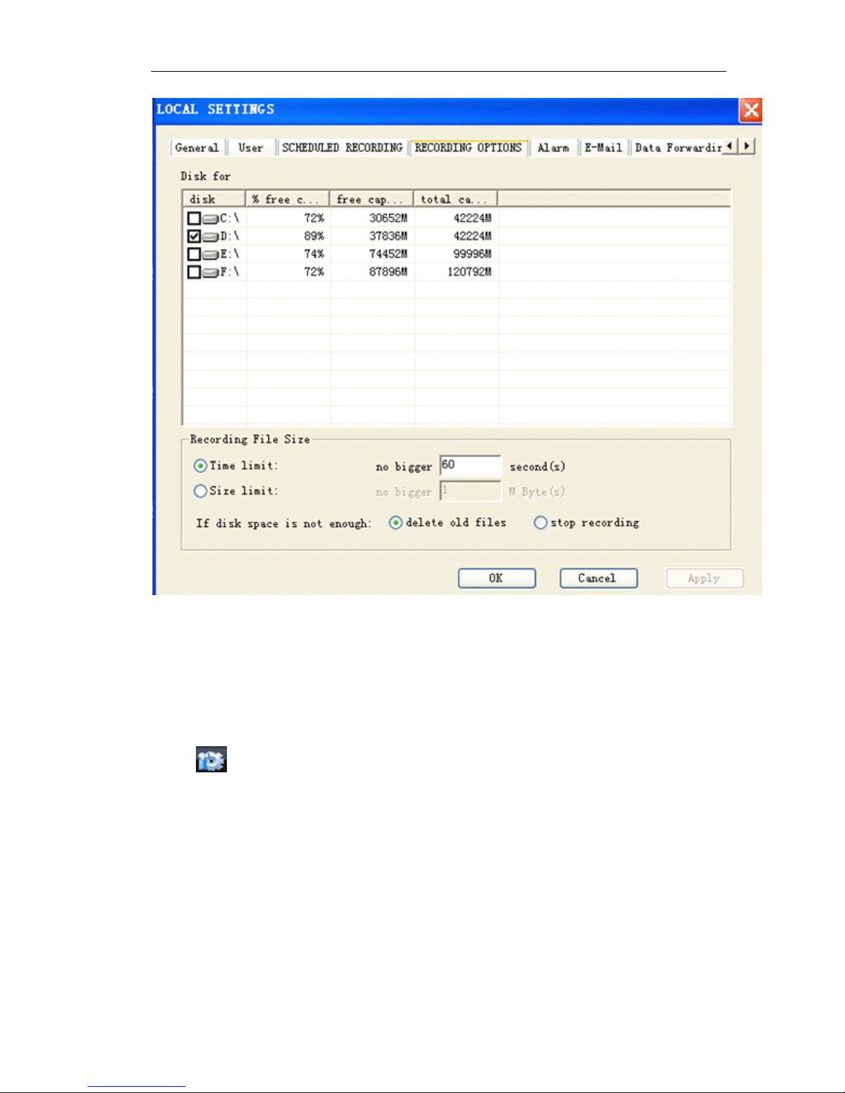
Page 66 of 87
Record
Record
Record
Record file
file
file
file packing
packing
packing
packing size:
size:
size:
size:
Time limit: default setting is that pack a record file per one minute. 1 second to
999,999,999 seconds can be defined.
Size limit: pack the record file by file size. 1Mega Byte to 999,999,999 Mega Bytes can
be defined.
6.7.2
6.7.2
6.7.2
6.7.2 Time
Time
Time
Time Schedule
Schedule
Schedule
Schedule record
record
record
record over
over
over
over Management
Management
Management
Management Software
Software
Software
Software
Click button in main menu to pop up the local setting menu, enter the
“ Scheduled Recoding ” attribute page as following figure:
Page 67
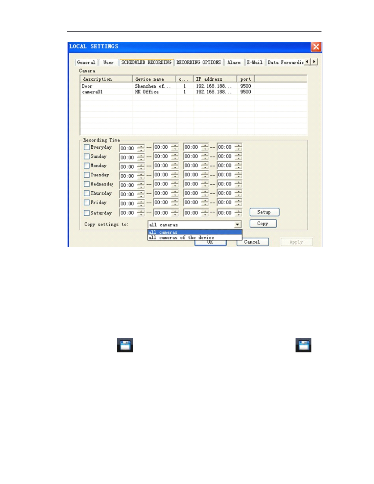
Page 67 of 87
Note:
For enabling timer record function, the Network Camera must enable automatically
login server function firstly, please refer to “ server management ” for details setting
Please do not close video when you enable the timer record, otherwise the system will
not record automatically. The client must logouts and re-logins to restore the timer
record.
6.7.3
6.7.3
6.7.3
6.7.3 Manual
Manual
Manual
Manual record
record
record
record
Start record and stop Record
Method 1: Click on the bottom of main menu to start record. Re-click to
stop the record.
Method 2: right click mouse on “ Camera 01 ” or right click mouse on video image
Choose “ Start Recording ” . Choose “ Stop Recording ” to stop the record.
Page 68
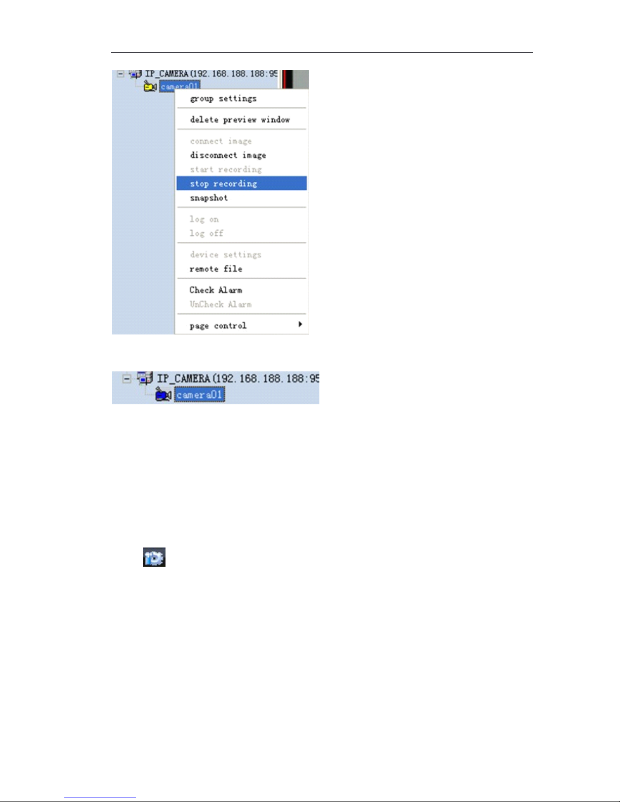
Page 68 of 87
camera icon change blue color to yellow color.
Stop record: right click mouse on “ Camera 01 ” or right click mouse on video image
Choose “ Stop Recording ”,camera icon is blue.
Note
Note
Note
Note : Blue camera icon: no record
Yellow camera icon: recording
6.7.4
6.7.4
6.7.4
6.7.4 Alarm
Alarm
Alarm
Alarm record
record
record
record
Enable alarm record setting:
Click button in main menu to pop up the local setting, enter the “ Alarm ”
attribute page; enable alarm record and set the record time.
Page 69
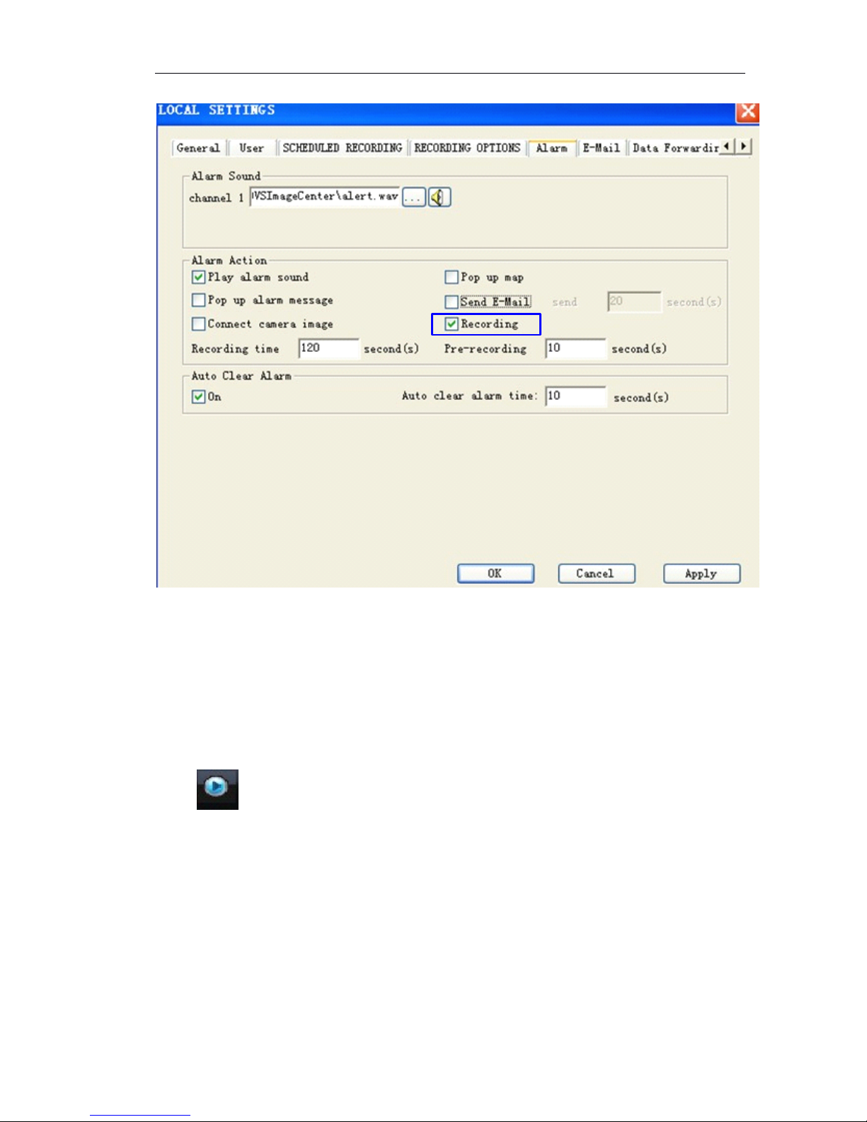
Page 69 of 87
Alarm Action:
1 Enable Recording
2 Set Recording time: 1-999,999,999 seconds can be defined.
3 Pre-recording: pre-alarm record, 1-999,999,999 seconds can be defined.
6.8
6.8
6.8
6.8 Playback
Playback
Playback
Playback
Click button in main menu to pop up the player menu, select the “ record file ”
to view videos.
Page 70
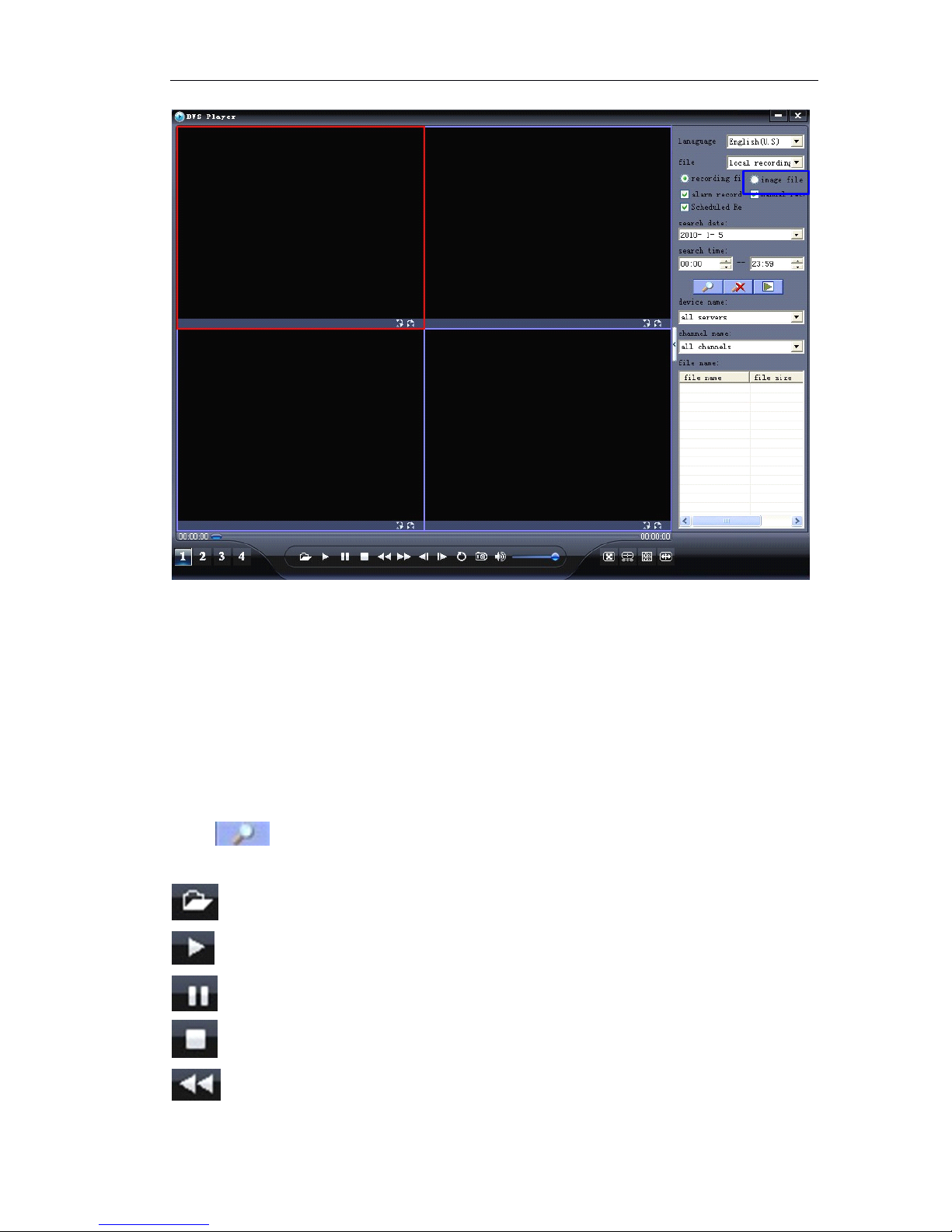
Page 70 of 87
Search
Search
Search
Search path:
path:
path:
path:
Local record: the files are saved in PC.
Remote download: the files are kept in SD card of IP camera.
Record
Record
Record
Record type:
type:
type:
type:
Alarm record: includes the motion detection record and sensor alarm record
Manual record
Scheduled record: time schedule record
Search
Search
Search
Search mode
mode
mode
mode : define the search condition, Search by devices and Search by date.
Click to begin search.
: open the record files to playback.
: begin to play
: Pause
: stop to play
: Fast backward
Page 71
Page 71 of 87
: Forward, the speed can be defined. 2X, 4X, 8, 16X and 1/2X, 1/4X, 1/8X and
1/16X speed
: Single frame backward
: single frame forward
: cycle play
: Snapshot
: play audio
6.9
6.9
6.9
6.9 Alarm
Alarm
Alarm
Alarm management
management
management
management
Alarm action includes:
1. Enable local sound alarm
2. Pop up alarm message
3 . Automatically pop up camera video
4. Pop up electronic map
5. Email notification
6. Enable corresponding channel record
6.9.1
6.9.1
6.9.1
6.9.1 Sound
Sound
Sound
Sound Alarm
Alarm
Alarm
Alarm
Enable “ Play alarm sound ”
Alarm sound can be defined.
Auto Clear alarm time: after defined time, stop to play alarm sound.
Page 72
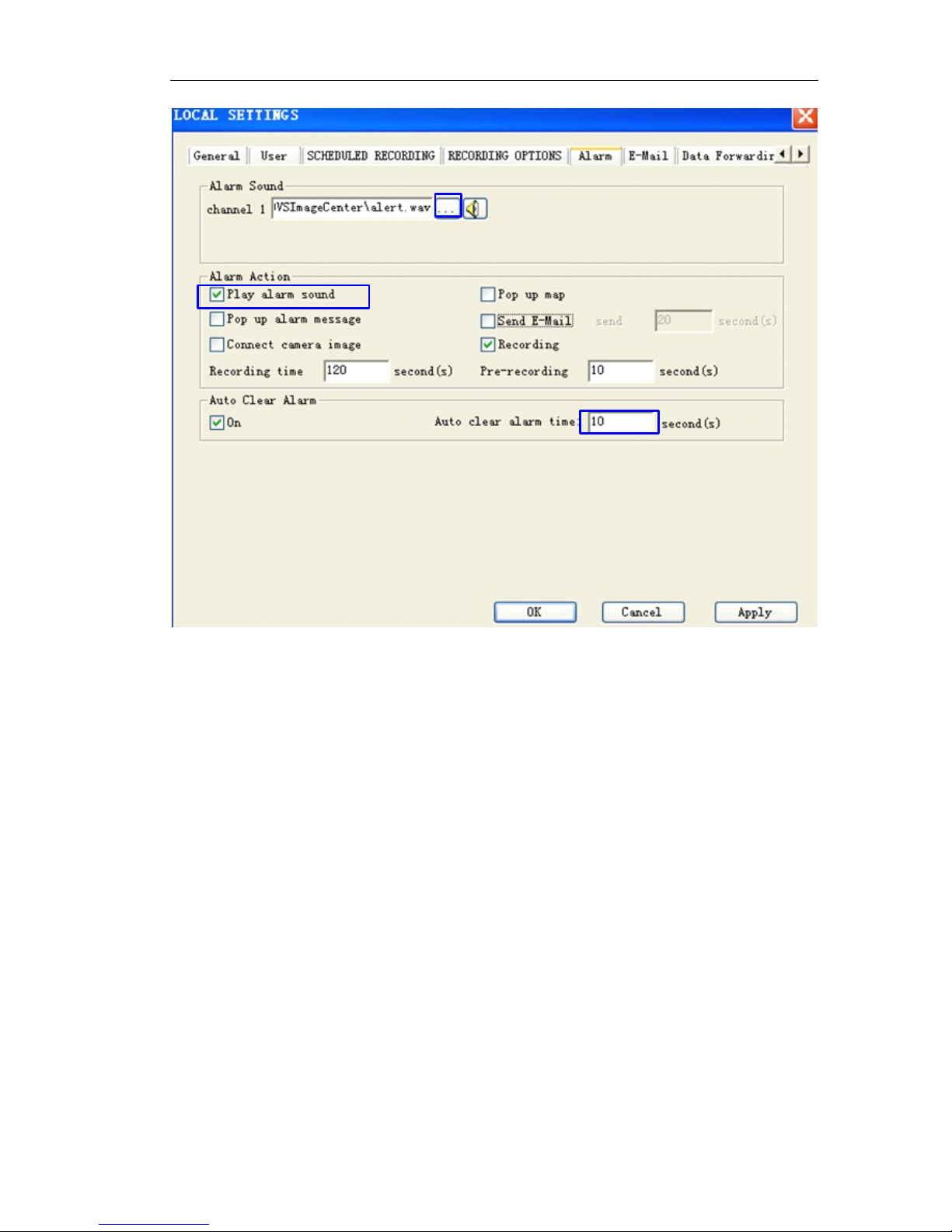
Page 72 of 87
6.9.2
6.9.2
6.9.2
6.9.2 Pop
Pop
Pop
Pop up
up
up
up alarm
alarm
alarm
alarm message
message
message
message
Enable “ Pop up alarm message ”
Page 73
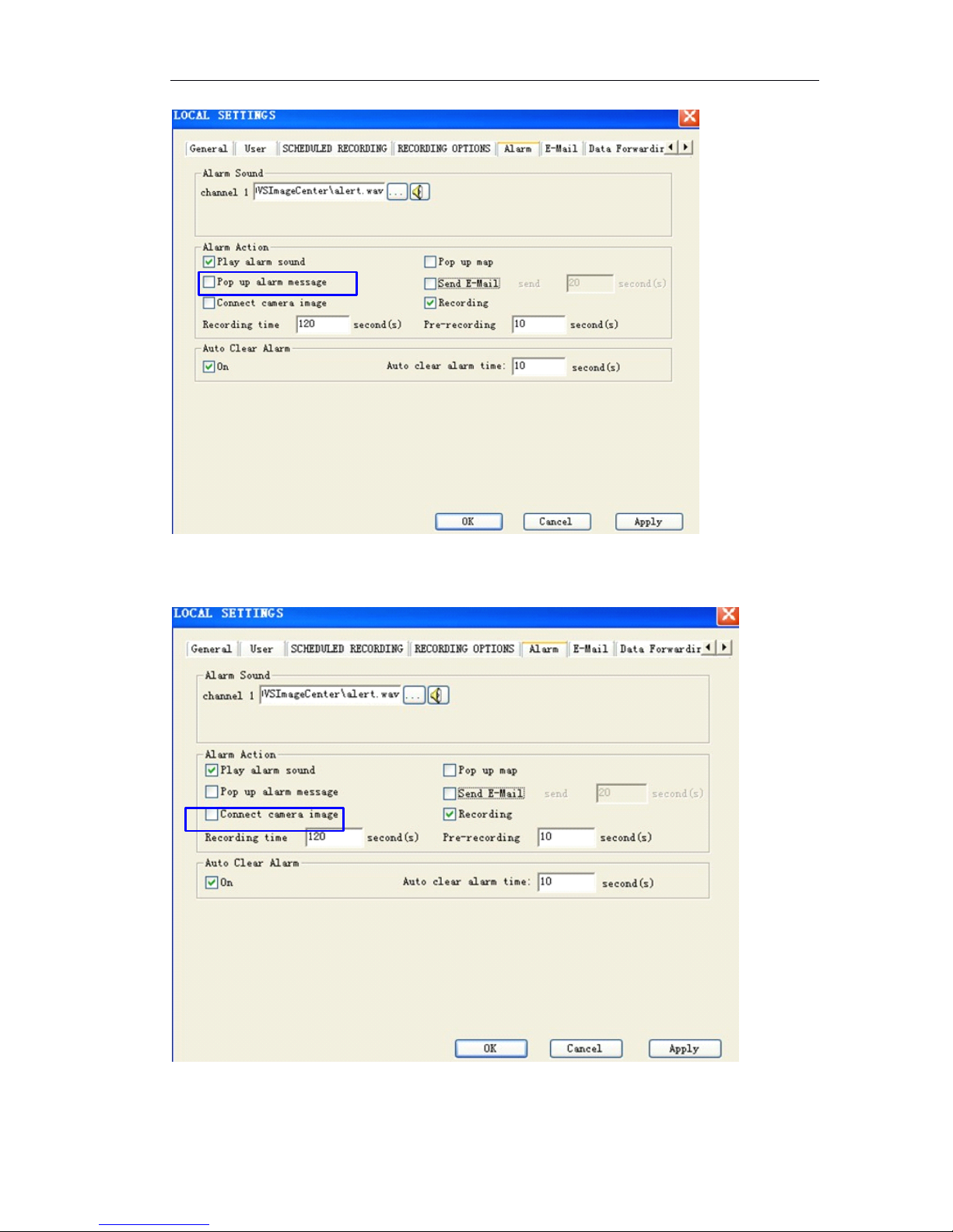
Page 73 of 87
6.9.3
6.9.3
6.9.3
6.9.3 Pop
Pop
Pop
Pop up
up
up
up camera
camera
camera
camera video
video
video
video
Enable “ Connect camera image ”,once alarm, automatically open the video.
Page 74
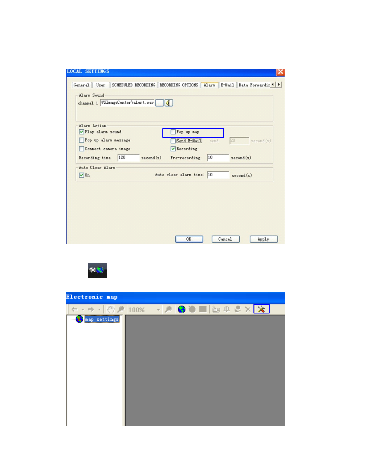
Page 74 of 87
6.9.4
6.9.4
6.9.4
6.9.4 Electronic
Electronic
Electronic
Electronic Map
Map
Map
Map alarm
alarm
alarm
alarm
Once alarm, it pops up Electronic Map.
Method 1: Enable “ Pop up map ”
,
Method 2:
1 Click button in main menu to pop up the electronic map setting as below.
Page 75

Page 75 of 87
2 Click button, enter the “ Electronic Map Settings ”
2
2
2
2 Edit
Edit
Edit
Edit Electronic
Electronic
Electronic
Electronic Map
Map
Map
Map
1)
1)
1)
1) Add
Add
Add
Add map
map
map
map
Right click mouse on “ Map Setting ” to click “ Add Sub Map ”,open the Map in jpeg or
bmp format.
Page 76
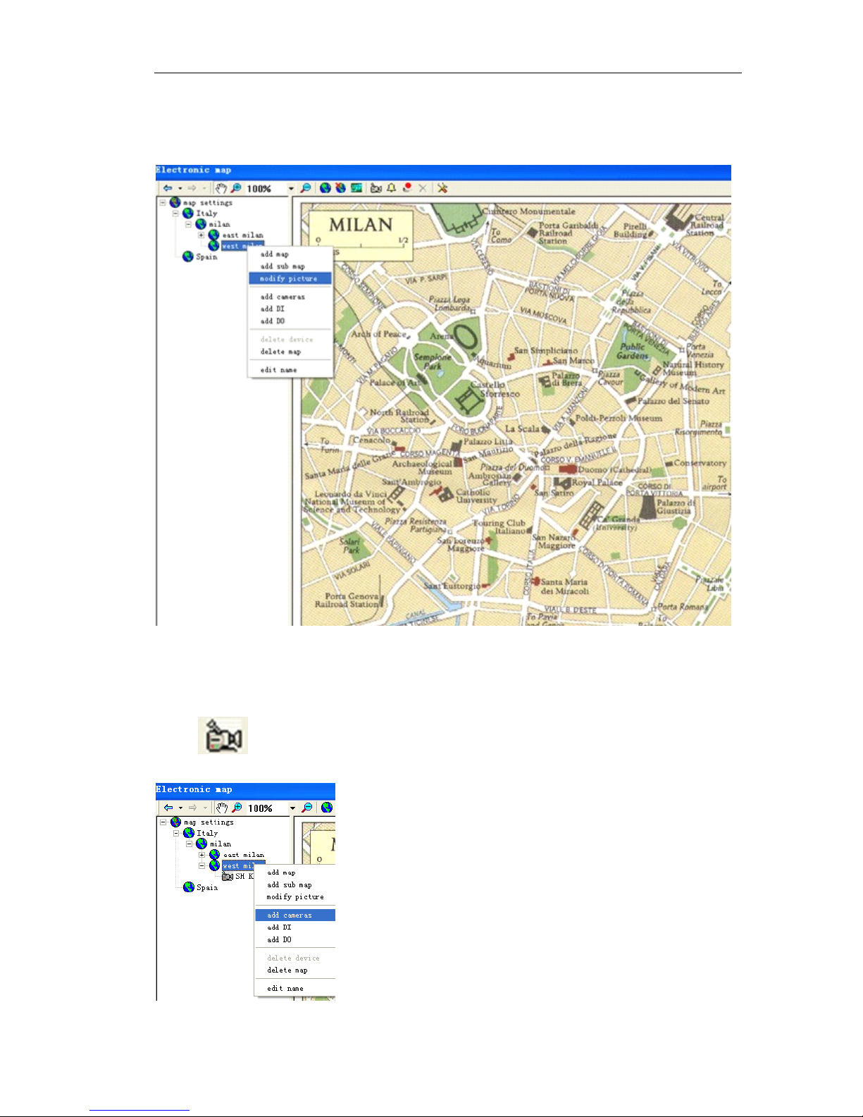
Page 76 of 87
2)
2)
2)
2) Modify
Modify
Modify
Modify map
map
map
map
Right click mouse on “ Map Name ” (e.g. Milan), click modify picture
3)
3)
3)
3) Delete
Delete
Delete
Delete map
map
map
map
Right click mouse on “ Map Name ” (e.g. Milan), click delete map.
4)
4)
4)
4) Add
Add
Add
Add IP
IP
IP
IP cameras
cameras
cameras
cameras
Click button on the top menu or Right click mouse on “ Map name ”,click
“ Add cameras ” .
Page 77
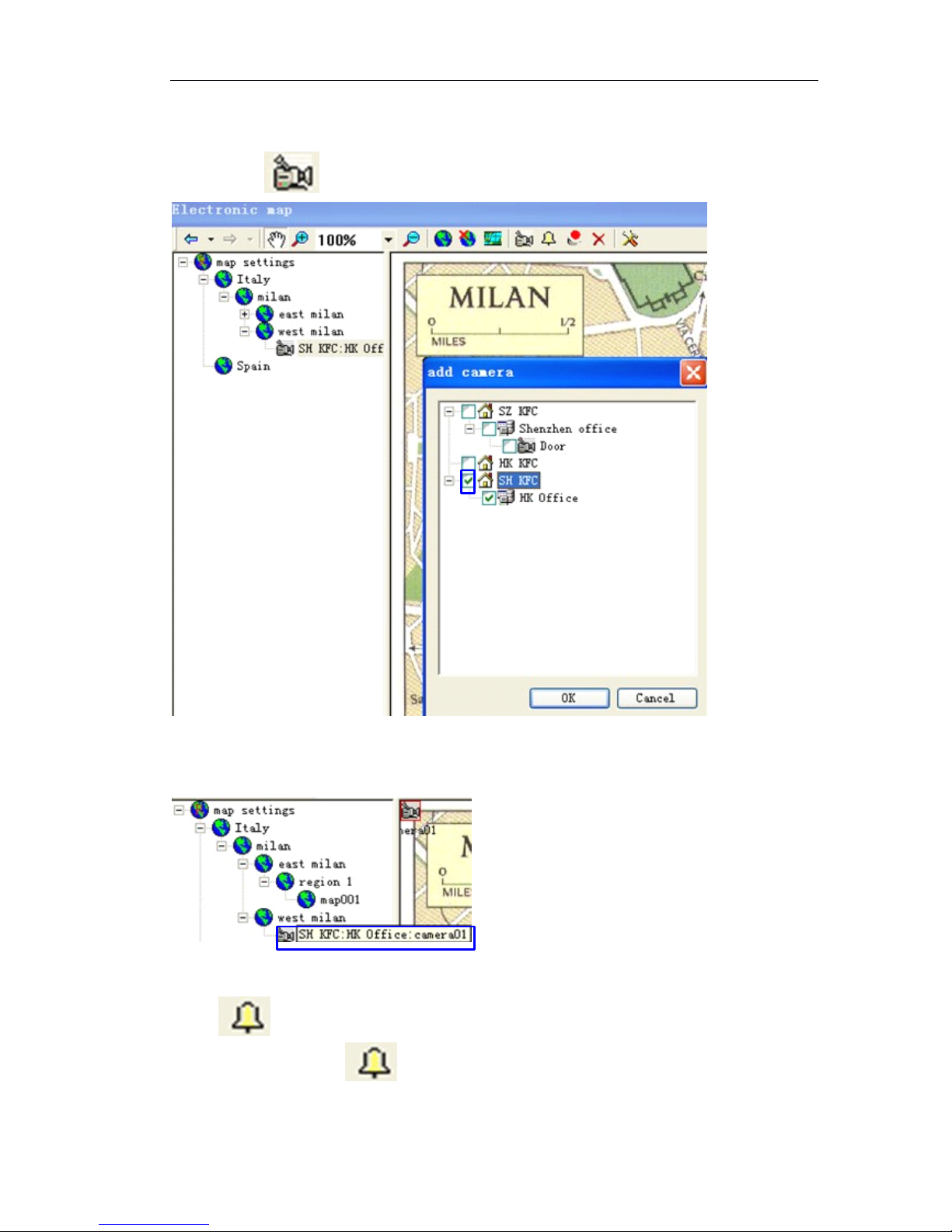
Page 77 of 87
Choose the IP cameras which you would like to add, one group IP camera or multiple
groups IP camera or one IP camera can be selected, Click “ OK ” to save changes.
You will see icon on the map, drag it to the appointed position on the map.
5)
5)
5)
5) View
View
View
View the
the
the
the video
video
video
video
Double click on IP camera name, it will pop up a window to show the camera video.
6)
6)
6)
6) Add
Add
Add
Add sensor
sensor
sensor
sensor alarm
alarm
alarm
alarm input
input
input
input
Click button on the top menu or Right click mouse on “ Map name ”,click
“ Add DI ” . You will see icon on the map, drag it to the appointed position on
the map.
Page 78
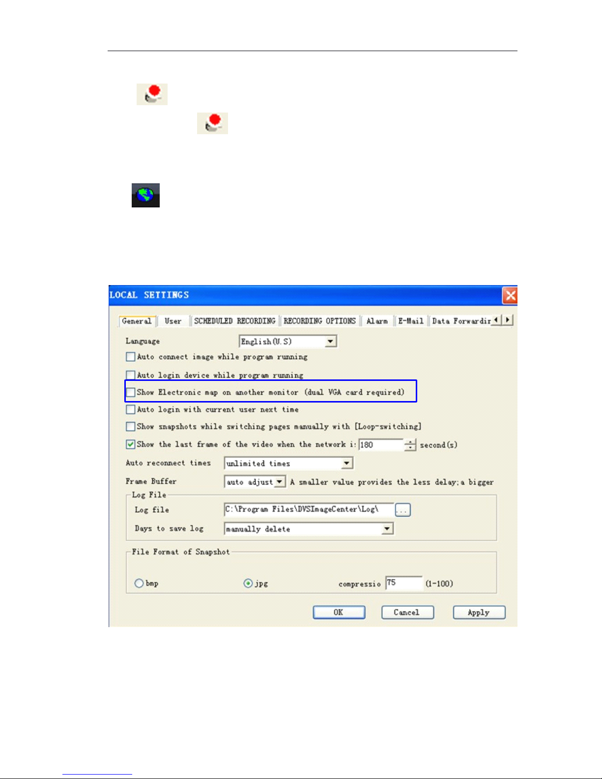
Page 78 of 87
7)
7)
7)
7) Add
Add
Add
Add alarm
alarm
alarm
alarm output
output
output
output
Click button on the top menu or right click mouse on “ map name ”,click “ Add
DO ” . You will see icon on the map, drag it to the appointed position on the
map.
3
3
3
3 Viewing
Viewing
Viewing
Viewing Electronic
Electronic
Electronic
Electronic Map
Map
Map
Map
Click button in main menu to view electronic map..
4
4
4
4 Show
Show
Show
Show electronic
electronic
electronic
electronic map
map
map
map on
on
on
on another
another
another
another monitor
monitor
monitor
monitor
Enable “ Show electronic map on another monitor ”,Live video of IP Camera is
displayed by one monitor, electronic map is displayed by another monitor.
Note
Note
Note
Note : Make sure the PC supports dual display card.
6.9.5
6.9.5
6.9.5
6.9.5 Email
Email
Email
Email notification
notification
notification
notification
If failed to sign in IP camera, video lost, motion detection trigger or sensor alarm trigger ,
it will send alarm notification by email. Enable “ Send E-mail ” .
Page 79
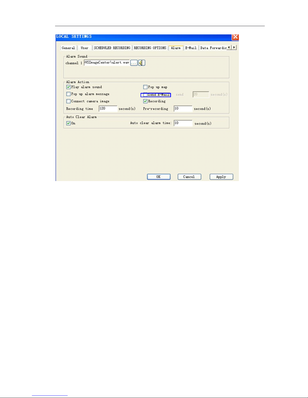
Page 79 of 87
Enter into “ Email ” attribute page as below
Page 80
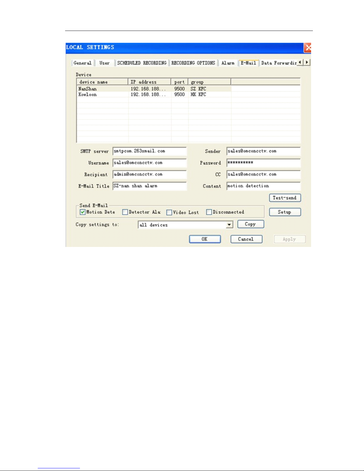
Page 80 of 87
(1) 『 SMTP Server 』 Input the SMTP Server, e.g. smtp.sohu.com.
(2) 『 user name 』 Input the full name of email address.
(3) 『 password 』 Input password to login email address.
(4) 『 Sender email』Input the sending email address. Sending email address should b e
same as email address of 『 user name 』
(5) 『 Receipt 』 The email address which receive the alarm notification.
(6) 『 C.C 』 to make a copy to email address which can receive the alarm notification
(7) 『 E-mail Title 』 define the email subject.
(8) 『 Content 』 define the email content.
(9)
(9)
(9)
(9) Select
Select
Select
Select the
the
the
the alarm
alarm
alarm
alarm type
type
type
type
Motion Dete: motion detection. When the defined object is moved, send alarm
notification.
Detector Ala: sensor alarm. When sensor alarm is triggered, send alarm notification.
Video lost: when video is lost, send alarm notification.
Disconnected: when network connection is failed, send alarm notification.
(10)
(10)
(10)
(10) Copy
Copy
Copy
Copy settings
settings
settings
settings to
to
to
to other
other
other
other devices
devices
devices
devices
All devices: the Email settings will be copied to all IP cameras.
All devices in the group: the email settings will be copied to all IP cameras in the same
group. Click 『 Copy 』 and 『 Apply 』 to save changes.
Page 81
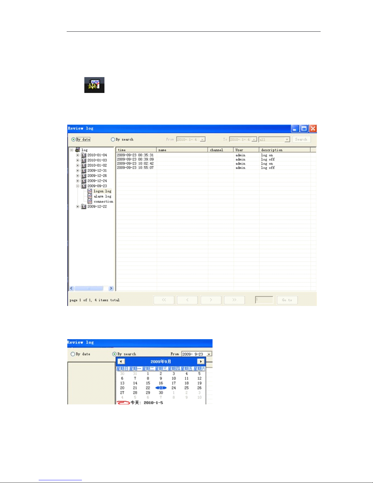
Page 81 of 87
6.9.6
6.9.6
6.9.6
6.9.6 History
History
History
History event
event
event
event
History event includes the system event, alarm event and network connection event.
Click button on the bottom of main menu to pop up the following figure
You can search the history event by date or by event type.
Search
Search
Search
Search the
the
the
the history
history
history
history event
event
event
event by
by
by
by date.
date.
date.
date.
Search
Search
Search
Search the
the
the
the history
history
history
history event
event
event
event by
by
by
by event
event
event
event type.
type.
type.
type.
Input ‘ start date ” or select date from drop down menu and end date.
Page 82
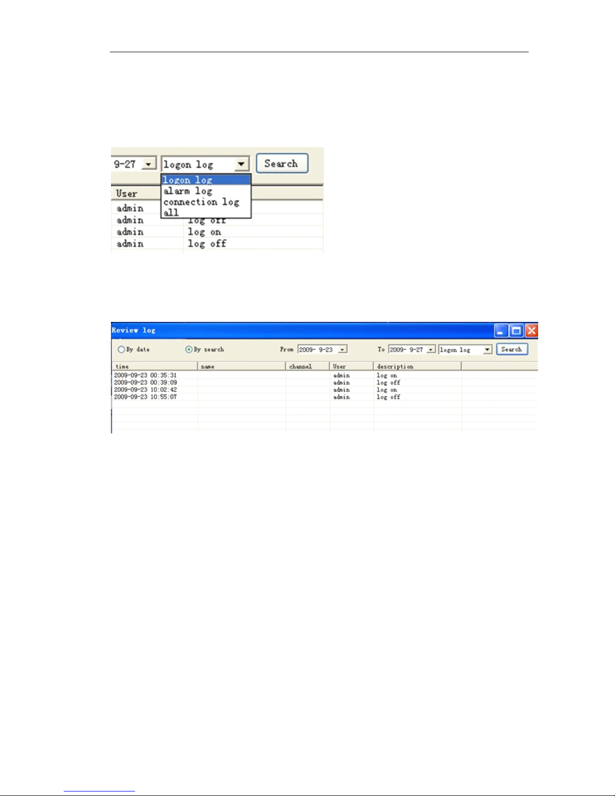
Page 82 of 87
Select the event type:
logon log: log in event;
alarm log: motion detection, sensor alarm event
connection log: network connection failed event
After you define the search conditions, click 『 Search 』
,
it shows the following search
result:
General
General
General
General Settings
Settings
Settings
Settings for
for
for
for History
History
History
History event
event
event
event
『 Days to save log
』
how many days you would like to save log. 10days, 20days, 30day s
or manually delete.
Page 83
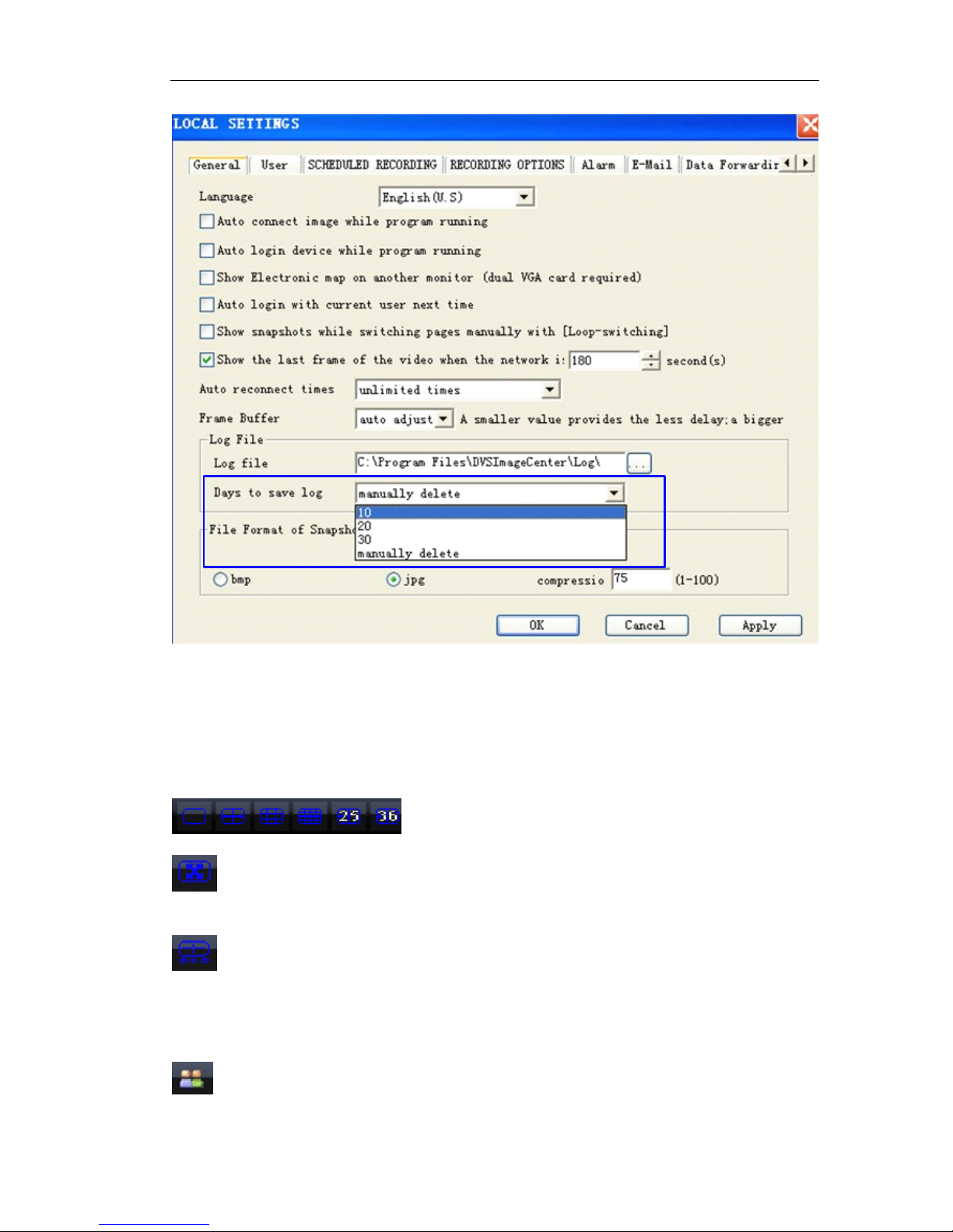
Page 83 of 87
6.10
6.10
6.10
6.10 Toolbar
Toolbar
Toolbar
Toolbar
6.10.1
6.10.1
6.10.1
6.10.1 Bottom
Bottom
Bottom
Bottom Toolbar
Toolbar
Toolbar
Toolbar
Part
Part
Part
Part I
: 1/4/9/16/25/36ch Multiview
: Full screen, Video image displayed on the screen will be maximized. Right click
mouse to cancel the full screen.
: show quick buttons.
Part
Part
Part
Part II
II
II
II
: log in IP camera
Page 84
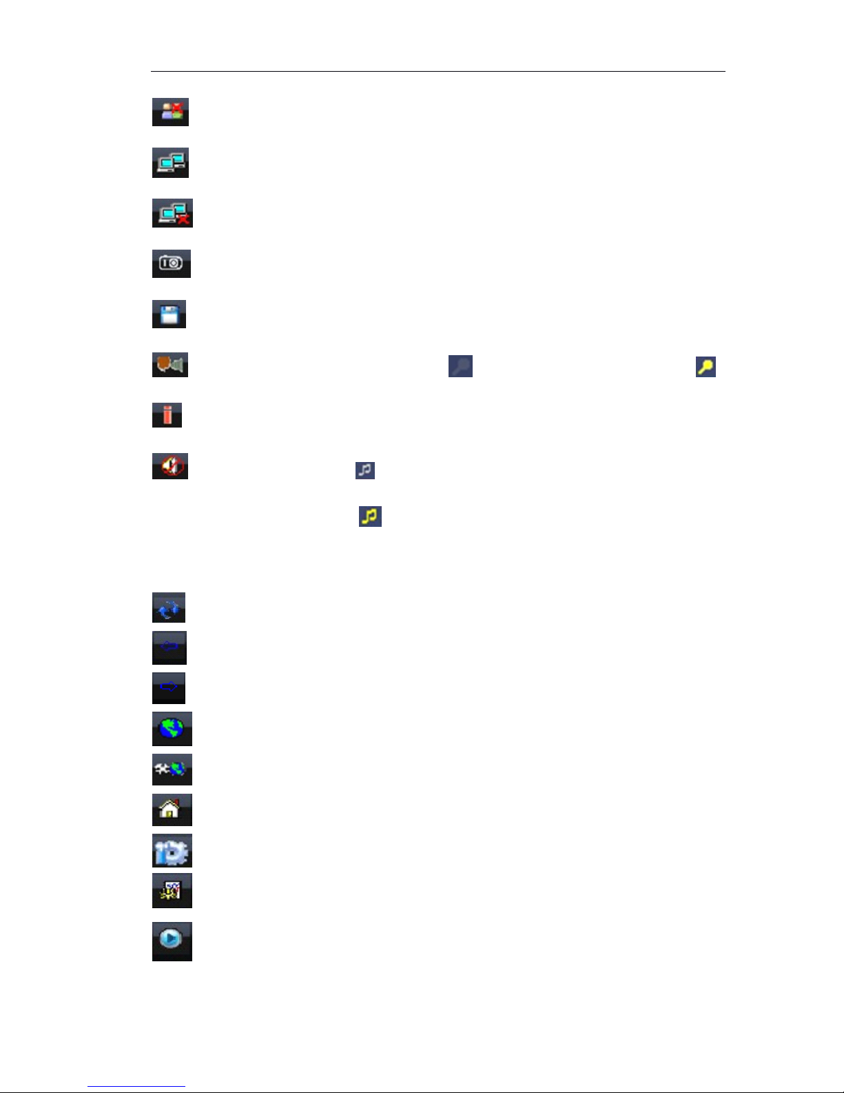
Page 84 of 87
: log off IP camera
: Connect Image.
: Disconnect image.
: manually Snapshot
: manually record
: talk with IP camera, enable it, the icon on Ip camera video changes to .
: Clear alarm
:stop the audio, the icon on IP camera video is grey.
When start the audio, the icon becomes yellow.
Part
Part
Part
Part III
III
III
III
:Manually loop switch
: Switch to previous screen
: Switch to next screen
: view electronic map
: Electronic map settings
: group settings, add multiple IP cameras
: settings for Management Software
: Check history event
: Playback the record files of IP camera or in PC.
Page 85
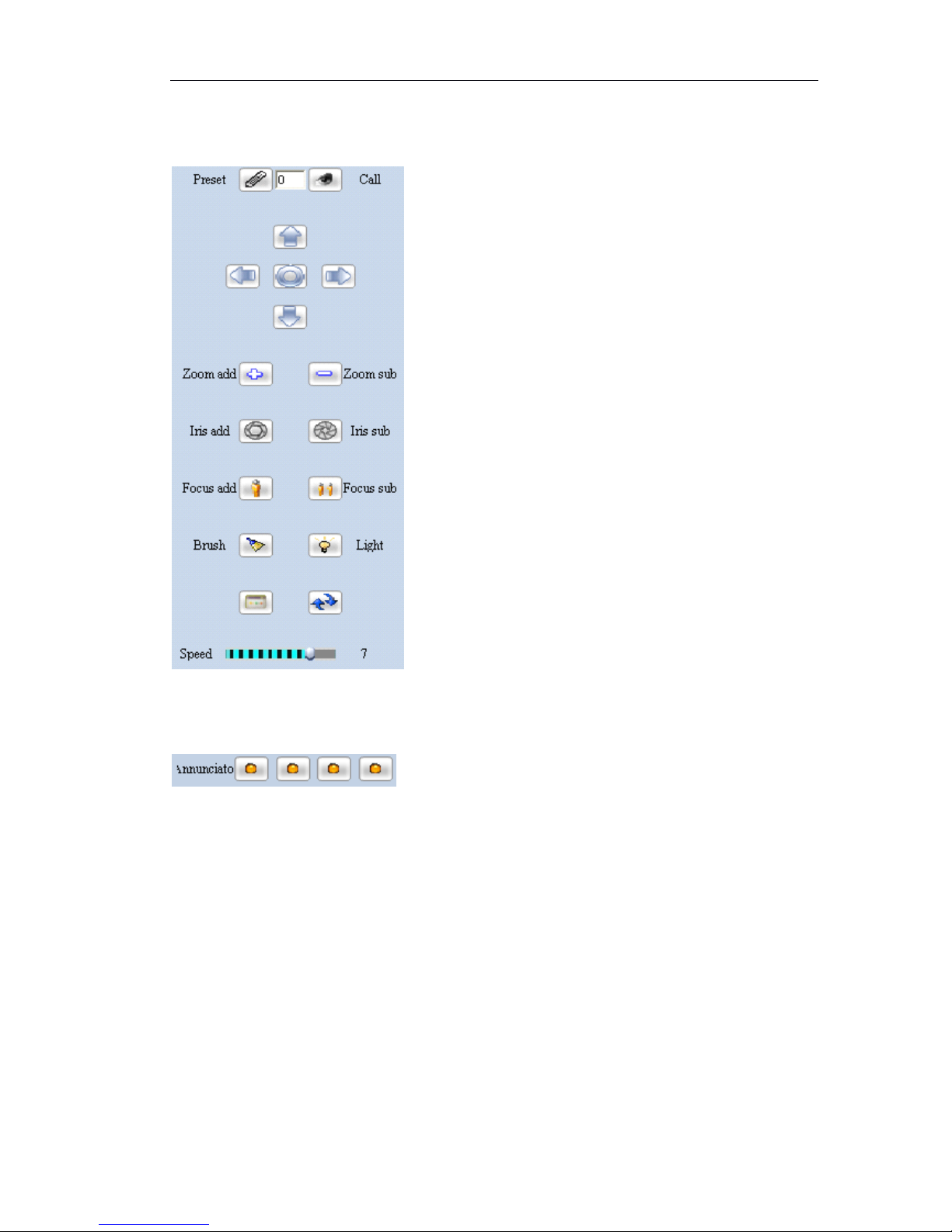
Page 85 of 87
6.10.2
6.10.2
6.10.2
6.10.2 PTZ
PTZ
PTZ
PTZ Control
Control
Control
Control Toolbar
Toolbar
Toolbar
Toolbar
6.10.3
6.10.3
6.10.3
6.10.3 Alarm
Alarm
Alarm
Alarm Control
Control
Control
Control Toolbar
Toolbar
Toolbar
Toolbar
Alarm Output: alarm output status. The indicator will light up if trigger alarm output.
When you click the lamp to light it up, this will trigger the alarm output.
7
7
7
7 Appendix
Appendix
Appendix
Appendix
7.1
7.1
7.1
7.1 FAQ
FAQ
FAQ
FAQ
If you have problems in using, please refer to following steps to check and solve them
Check hardware and interface
Please check you power supply firstly, and then check if your network is connected,
lastly check if your cables are well connected. If there is not any problem with them
Page 86

Page 86 of 87
please see if the lights are flashing properly on the front panel referring to table 3.
Continue to next step if all of the following checking items are well.
Upgrade software
Check if the software is the latest version according to the “ advanced setting ”
section. Upgrade it if not. Generally the latest version software will solve some
problems and will be more stable than old version software.
Contact technical support
Please contact technical support or browse our website for technical consultation if
the problem is not solved.
Frequent problems solutions
a 、 can not visit Network Camera via browser
Possible reason: network disconnected
Solution: Connect network with PC to check if the network is connected well. Firstly
check cable failure, network problems caused by virus, until check network is
connecting successfully by using ping command
Possible reason: IP address conflict
Solution: Disconnect the server ’ s network and connect server with PC to reset IP
address according recommended operations
Possible reason: IP address in different subnets
Solution: Check the IP address and subnet mask of server and gateway
Possible reason: web port is changed
Solution: Contact network administrator to obtain corresponding port information
Possible reason: unknown
Solution: Reset server to the factory settings and re-connect network. The default IP
address of system is 192.168.188.188
b 、 can not control dome
Possible reason: signal cable is not connected or not connected properly
Solution: Re-connect control cable with dome and server
c 、 can not view normal image
Possible reason: OS is Win98
Solution: Install DirectX8.0 or later version
d 、 can not use Media player to play the record file
Solution: Download and install divx common decoder.
Page 87

Page 87 of 87
7.2
7.2
7.2
7.2 factors
factors
factors
factors influencing
influencing
influencing
influencing system
system
system
system capability
capability
capability
capability
You muse consider the whole system capability issue, factors influencing your system
and system optimized settings when you set up your system. Bandwidth including
stream rate setting, frame rate, and too many client connections influencing frame
rate is the main issue that we need to consider.
Following are the common factors that will influence the server efficiency that we
need to concise:
Firstly is your bandwidth. Generally in LAN the bandwidth is not a problem but we must
consider the upload bandwidth in WAN or some private networks. If the upload
bandwidth is 513k or lower, you would better set the output stream of server within
512k, o therwise there the video or audio will not play fluently.
We must emphasize the ADSL. Usually we are considering the download bandwidth of
ADSL, but in the Network Camera application, we are using its upload bandwidth. Thus
at this point we have to concern about the upload bandwidth for the system design,
for ex ample, for an ADSL with 1.5M download bandwidth, the upload bandwidth is less
than 512k. Thus the upload bandwidth is what we have to concern about mostly for
network design.
About the image parameter setting according to network please refer to “ image
advanced setting ” in “ image setting ”
Too many clients viewing from a Network Camera will influence the server capability
cause the frame reducing. Consequently, we recommend that the maximum viewing
connections is 20 channels.
Capture function provided by Network Camera is using the front-side high definition
image capture method. Frequently capture will influence the server capability and
cause frame rate reducing.
Too much network load will influence the system capability and cause the audio and
video playing not fluently.
CPU capability insufficiency will cause the audio and video playing not fluently.
Wireless transmission will cause the disconnection and server re-connection from client
due to the unstable of wireless network.
 Loading...