

Omcan Food Machinery IC-CN-0040 Installation Manual
Ice Maker
Model IC-CN-0040
Instruction Manual
Revised - 1/5/2015
Toll Free: 1-800-465-0234
Fax: 905-607-0234
Email: sales@omcan.com
www.omcan.com

Table of Contents
Model IC-CN-0040
Section
General Information
Safety & Warranty
Technical Specications
Installation
Operation
Maintenance
Troubleshooting
---------------------------------------------------------------------------------------------------------- 7
----------------------------------------------------------------------------------------------------- 8 - 10
----------------------------------------------------------------------------------------------- 10 - 13
----------------------------------------------------------------------------------------- 3 - 4
------------------------------------------------------------------------------------------------ 4
------------------------------------------------------------------------------------------- 13 - 20
Page
------------------------------------------------------------------------------------ 5 - 6
French Instructions
Spanish Instructions
Parts Breakdowns
Electrical Schematics
Notes
Warranty Registration
-------------------------------------------------------------------------------------------------------------- 58
--------------------------------------------------------------------------------------- 20 - 36
---------------------------------------------------------------------------------------- 55 - 56
------------------------------------------------------------------------------------- 37 - 54
------------------------------------------------------------------------------------------ 57
----------------------------------------------------------------------------------------- 59
2

General Information
Omcan Manufacturing and Distributing Company Inc. and Food Machinery of America, Inc. dba Omcan
are not responsible for any harm or injury caused due to any person’s improper or negligent use of
this equipment. The product shall only be operated by someone over the age of 18, of sound mind, and
not under the inuence of any drugs or alcohol, who has been trained in the correct operation of this
machine, and is wearing authorized, proper safety clothing. Any modication to the machine voids any
warranty, and may cause harm to individuals using the machine or in the vicinity of the machine while
in operation.
CHECK PACKAGE UPON ARRIVAL
Upon receipt of an Omcan shipment please inspect for external damage. If no damage is evident on the
external packaging, open carton to ensure all ordered items are within the box, and there is no concealed
damage to the machine. If the package has suffered rough handling, bumps or damage (visible or concealed),
please note it on the bill of lading before accepting the delivery and contact Omcan within 24 hours, so we may
initiate a claim with the carrier. A detailed report on the extent of the damage caused to the machine must be
lled out within three days, from the delivery date shown in the shipping documents. Omcan has no recourse
for damaged products that were shipped collect or third party.
Omcan Fabrication et distribution Companie Limité et Food Machinery d’Amerique, dba Omcan ne
sont pas responsables de tout dommage ou blessure causé du fait que toute personne ait utilisé
cet équipement de façon irrégulière. Le produit ne doit être exploité que par quelqu’un de plus de 18
ans, saine d’esprit, et pas sous l’inuence d’une drogue ou d’acohol, qui a été formé pour utiliser
cette machine correctement, et est vêtu de vêtements de sécurité approprié. Toute modication de la
machine annule toute garantie, et peut causer un préjudice à des personnes utilisant la machine ou
des personnes à proximité de la machine pendant son fonctionnement.
VÉRIFIEZ LE COLIS DÈS RÉCEPTION
Dès réception d’une expédition d’Omcan veuillez inspecter pour dommages externes. Si aucun dommage
n’est visible sur l’emballage externe, ouvrez le carton an de s’assurer que tous les éléments commandés
sont dans la boîte, et il n’y a aucun dommage dissimulé à la machine. Si le colis n’a subi aucune mauvaises
manipulations, de bosses ou de dommages (visible ou cachée), notez-le sur le bond de livraison avant
d’accepter la livraison et contactez Omcan dans les 24 heures qui suivent, pour que nous puissions engager
une réclamation auprès du transporteur. Un rapport détaillé sur l’étendue des dommages causés à la machine
doit être rempli dans un délai de trois jours, à compter de la date de livraison indiquée dans les documents
d’expédition. Omcan n’a aucun droit de recours pour les produits endommagés qui ont été expédiées ou cueilli
par un tiers transporteur.
Omcan Empresa De Fabricacion Y Distribucion Inc. Y Maquinaria De Alimentos De America, Inc. dba
Omcan no son responsables de ningun daño o perjuicío causado por cualquier persona inadecuada o
el uso descuidado de este equipo. El producto solo podra ser operado por una persona mayor de 18
años, en su sano juicio y no bajo alguna inuencia de droga o alcohol, y que este ha sido entrenado
en el correcto funcionamiento de esta máquina, y ésta usando ropa apropiada y autorizada. Cualquier
modicación a la máquina anúla la garantía y puede causar daños a las personas usando la máquina
mientras esta en el funcionamiento.
3

General Information
REVISE EL PAQUETE A SU LLEGADA
Tras la recepcion de un envio Omcan favor inspeccionar daños externos. Si no hay daños evidentes en el
empaque exterior, Habra el carton para asegurararse que todos los articulos solicitados ésten dentro de la
caja y no encuentre daños ocultos en la máquina. Si el paquete ha sufrido un manejo de poco cuidado, golpes
o daños (visible o oculto) por favor anote en la factura antes de aceptar la entrega y contacte Omcan dentro
de las 24 horas, de modo que podamos iniciar una reclamación con la compañia. Un informe detallado sobre
los daños causados a la máquina debe ser llenado en el plazo de tres días, desde la fecha de entrega que se
muestra en los documentos de envío. Omcan no tiene ningun recurso por productos dañados que se enviaron
a recoger por terceros.
Safety and Warranty
• Turn the unit off and unplug before performing any cleaning, maintenance or repairs.
• Do not operate the unit with a damaged power cord. If a damaged power cord is found, immediately turn
the unit off and unplug it. Do not operate again until trained personnel has xed the problem.
• Only operate the unit in a at, level ground. Do not place the unit near any heat sources.
• Only use original spare parts for repairs.
1 YEAR PARTS AND LABOUR WARRANTY
Within the warranty period, contact Omcan Inc. at 1-800-465-0234 to schedule an Omcan authorized
service technician to repair the equipment locally.
Unauthorized maintenance will void the warranty. Warranty covers electrical and part failures not
improper use.
WARNING:
The packaging components (cardboard, polyethylene, and others) are classied as normal solid urban waste
and can therefore be disposed of without difculty.
In any case, for suitable recycling, we suggest disposing of the products separately (differentiated
waste) according to the current norms.
DO NOT DISCARD ANY PACKAGING MATERIALS IN THE ENVIRONMENT!
4
Technical Specications
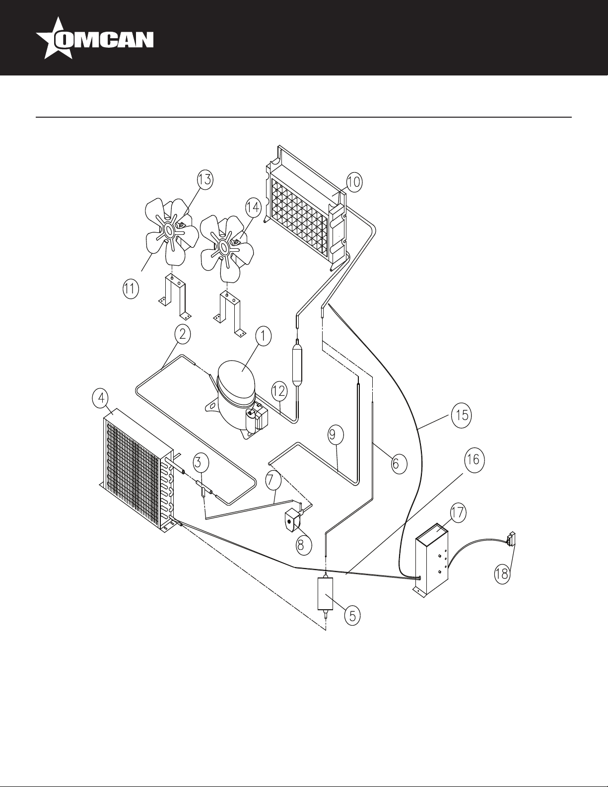
MAIN COMPONENTS
1. Compressor
2. Discharge Tube
3. Three Ways Adapter
4. Condensers
5. Drier and Filter
6. Capillary Tube
7. Connection Tube
8. Hot Gas Valve
9. Hot Gas Tube
10. Evaporator
11. Fan Blade
12. Suction Pipe
5
13. Motor (5W)
14. Motor (10W)
15. Temperature Sensor of Evaporator
16. Temperature Sensor of Condenser
17. Controller
Technical Specications
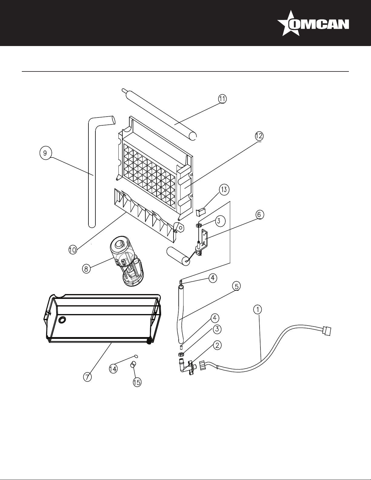
MAIN COMPONENTS
1. Water Supply Tube
2. Water Inlet Connector
3. Nut of Water Inlet Tube
4. Supporting Tube
5. Water Pump Inlet Tube
6. Floater Valve
7. Water Trough
8. Water Pump
9. Water Pump Outlet
Tube
6
10. Ice Slideway
11. Water Distribution Tube
12. Evaporator
13. Magnetic Switch
14. Gasket
15. Screw Cap

Installation
Note: Installation should be performed by a trained Service Technician. For proper operation of the ice
machine, the following installation guidelines must be followed. Failure to do so may result in loss of production
capability, premature part failure, and may void any warranties.
AMBIENT OPERATING TEMPERATURES
Minimum Operating Temperature: 50°F (10°C).
Maximum Operating Temperature: 100°F (38°C).
Note: The unit is not designed for outdoor use.
INCOMING WATER SUPPLY
Minimum incoming water temperature: 40°F (5°C).
Maximum incoming water temperature: 90°F (32°C).
Minimum incoming water pressure: 15 psig.
Maximum incoming water pressure: 80 psig.
Note: If water pressure exceeds 80 psig, a water pressure regulator must be installed.
DRAINS
Route bin drain, purge drain and water condenser drain must be individually connected to a oor drain. The
use of condensation pumps for draining water on equipment should not produce over 200 lbs./day. Omcan
assumes no responsibility for improperly installed equipment.
WATER FILTRATION
A water lter system should be installed with the ice machine.
CLEARANCE REQUIREMENTS
The unit must have a minimum of 6 inches (15 cm) of clearance at the rear, top, and sides of the ice machine
for proper air circulation. When using models which are located under the counter, circulation occurs from the
front. Top and side clearances are minimal.
STACKING
If the ice machines are to be stacked, refer to the instructions described later in this manual. Omcan does not
recommend stacking the unit.
DISPENSER APPLICATION
A thermostatic bin control kit must be installed if the ice machine is placed on a dispenser. A bin top may or
may not be required.
7

Operation
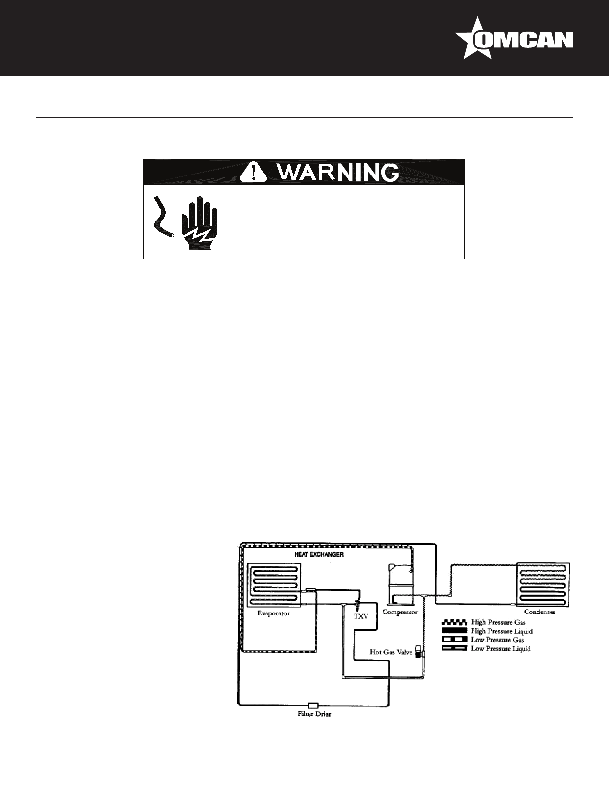
There are 3 systems: the Cooling System, the Water System and the Electrical System.
During the ice-making stage, the hot gas valve is closed. The hot refrigerant gas is pumped out of the
compressor to the condenser. The hot gas is cooled by a fan after passing through the condenser. The drier
and lter will reduce possible dirt and moisture in the refrigerant. The refrigerant expands in the evaporator
cooling so water will freeze. The low pressure refrigerant gas returns to the compressor from the evaporator
where the cycle continues. During the ice harvest stage, the valve is open. The hot refrigerant gas is pumped
out of the compressor to the evaporator through the hot gas valve. Since the hot gas i not cooled by the
condenser, the refrigerant warms the evaporator. Ice in contact with the evaporator begins to melt on the back
side. The ice gradually ice slides off of the evaporator and drops to the storage bin. When the water inlet is
connected with the main water supply, water will ll the trough through the oat valve until the water level
in the trough closes the valve. During the ice-making stage, water is pumped from the water trough to the
water distribution tube. The distributed water ows over the surface of the cold evaporator where the water is
converted to ice. The unfrozen water will return to the trough. At the end of the freeze cycle and during harvest,
the water dump valve is opened and the remaining water is pumped down the drain.
CIRCUIT DESCRIPTION
1. First time usage: The ice-maker must be properly installed. Switch the water tap on, let the water trough
ll, then turn the power switch to the ON position on the back panel. The ice-maker will start working
automatically. In this stage, the time is xed about 3 minutes. At this status, the White, Green, Yellow and
Red LEDs are light together.
2. Ice-making Status: The compressor, motor fan and pump are on. The hot gas valve is off. When the green
LED is lit, the unit is working in the ice making mode controlled by a temperature probe on the evaporator.
When the green LED is ashing, the unit is working in the ice making mode controlled by a xed timer. The
fan motor is also controlled by the condenser sensor. When the ambient temperature is too low, the motor
fan stops working.
3. Ice Harvest Status: The pump is off. The hot gas valve, compressor and motor fan are on. The fan motor
is also controlled by the condenser sensor. When the ambient temperature is too low, the motor fan stops
working. The Yellow LED indicates the ice harvest status.
4. Ice Full Status And Cold Preservation Stage: If the ice bin is lled with ice, the machine stops making
ice and turns to the cold preservation stage automatically. In this stage, the compressor works regularly
to keep the low temperatures so ice does not melt. The rest of the electric components are off. The
WHITE LED indicates the ice full status and the GREEN AND YELLOW LEDs together indicates the cold
preservation status.
5. Cleaning Status: Turn the machine’s CLEAN SWITCH to CLEAN for 3 minutes after the POWER SWITCH
is turned on. At this stage, the pump is on. Compressor, motor fan and are off. The GREEN and YELLOW
LEDs are ashing together. To stop the cleaning mode, turn the machine “OFF” or the unit will turn off
automatically after 30 minutes. NOTE: In order to start the Clean Status the unit must be on. The CLEAN
switch must be turned on within 3 minutes before the COMPRESSOR starts. Do not turn the CLEAN switch
on when machine is in ice-making status or ice-harvest status.
CONTROLLER BOX
Instructions for LEDs and buttons:
8

Operation
1. White LED: Ice full indicator light. When this LED is lit, the ice storage bin is full of ice or there is something
between the ice-full sensor and the evaporator. The unit will stop making ice. When ice cubes are taken out
of the ice storage bin making the ice-full probe free, the white LED will ash for 3 minutes. Then the unit will
restart and return to the ice making mode.
2. Green LED: Ice making indicator light. When this LED is lit, the unit is working in the ice making mode
controlled by a temperature probe on the evaporator. When the green LED is ashing, the unit is working in
the ice making mode controlled by a xed timer.
3. Yellow LED: Ice harvest indicator light. When this LED is lit, the unit is working in the ice harvest mode
controlled by ice-full probe. When green LED and yellow LED is lit, it means the unit is working in the cold
preservation stage .
4. Red LED: power indicator light. The unit is on when the red LED is lit.
5. Mode button: Mainly for service. When this button is pressed, it can change from ice making mode to ice
harvest mode, or from ice harvest mode to ice making mode. You can see the change of the mode from the
status of the green and yellow LEDs.
NOTE: If during the ice size adjustment, the “BIN FULL”, “ICE” and “HARVEST” LEDS blink all at once, this
indicates that the unit is in the default factory setting of the ice size adjustment.
CONTROL BOARD CHECKS
Timer Initiate
The timer initiate is a temperature sensor mounted on the liquid line to the evaporator. When the sensor
detects the correct low temperature, the freeze timer starts and the machine enters the timed portion of the
freeze cycle. When the freeze timer starts, the machine is in the timed portion of the freeze cycle. When
the machine enters harvest, the temperature rises, but the amount of time the machine is in harvest is
predetermined and is controlled by the Controller Board. Once the time has passed, the machine will enter the
harvest cycle. The timer is not adjustable, but the temperature at which the timer is initiated is adjustable.
ICE SIZE ADJUSTMENT
1. Press and hold the “Clean” button and the “Mode” button together for at least 3 seconds. The unit will
enter the Ice Size Adjustment mode. The GREEN LED will be blinking continuously during the ice size
adjustment.
2. While in the Ice Size Adjustment mode, press the “Clean” button or the “Mode” button for the desired ice
size.
Smaller ice setting: By pressing the “Clean” button, you can decrease the size of the ice cubes. The RED LED
will ash as you lower the ice size and will nally be blinking at the setting of smallest ice size.
Larger ice setting: By pressing the “Mode” button, you can increase the size of the ice cubes. The YELLOW
LED will ash as the larger size is set and will blink when the setting of largest ice size has been reached. After
10 seconds without any operation, the unit will automatically memorize the current setting and return to the
previous mode.
9
Operation
BIN CONTROL OPERATION
The bin control is used to shut the machine off when the bin lls with ice. The bin control must be checked
upon installation or initial startup and
when performing maintenance. There
is one bin switch for each evaporator.
The actuator arm of the bin switch
comes in contact with the splash
curtain. When the bin is full of ice,
the splash curtain is held open when
ice drops off of the evaporator. This
releases the pressure of the bin switch
actuator arm allowing the switch to
open. Units placed under counters
and machines without curtains: An ice slide at the bottom of the evaporator is used on all under the counter
units and some modular units. The slideway swivels up and down and has a magnetic reed switch which
detects its position. When ice is sitting on the control, the slideway faces down indicating that ice is present
(and disconnecting the circuit from the reed switch). When the ice is removed, the slideway swivels up and the
connection is completed allowing the machine to begin producing ice again.
BIN CONTROL ADJUSTMENT
All Models (except those without curtains): Check the bin switch for proper adjustment by swinging the bottom
of the curtain away from the evaporator. Slowly bring the curtain towards the evaporator. The switch should
close when the bottom edge of the curtain is even with the outer edge of the water trough. Adjust the switch
by loosening the screws which hold the switch in place. Move the switch to the proper position and retighten
the screws. Recheck the adjustment. Under the counter models or those without curtains: There are no
adjustments needed for the bin (magnetic reed) switch.
Maintenance
Before Maintenance:
1. Be sure the electrical supply is 115 VAC, 60Hz, 15A and is properly grounded to protect maintenance
personnel.
2. If any electrical parts are loose or if there is a danger of short circuiting, disconnect the power immediately.
MAINTENANCE PROCEDURE
1. Cleaning should be performed at least every 6 months. Local water conditions may require that cleaning be
performed more often.
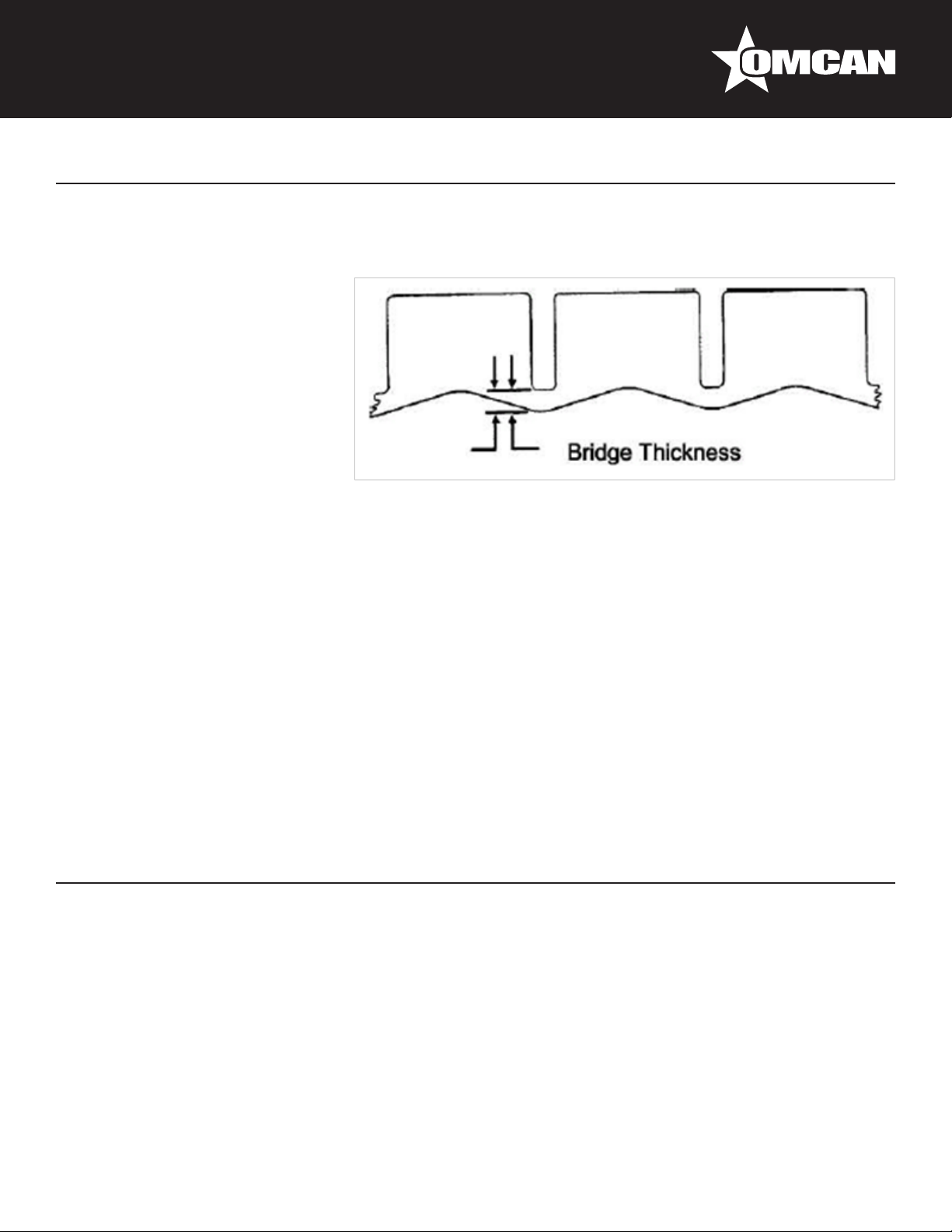
2. Check the ice bridge thickness. The thickness should be between 1/16-1/8’’.
3. Check the water level in trough. Check for proper water level and adjustment and troubleshoot if there is an
10

Maintenance
incorrect level.
4. Clean the condenser to ensure proper air ow.
5. Check for leaks of any kind: Water, Refrigerant, Oil, Etc.
6. Check the bin switch for proper adjustment.
7. Check all electrical connections.
8. Check the oil of the fan motor if applicable.
CLEANING AND SANITIZING
Problems may occur if the following procedures are not performed every 6 months:
1. Remove the front panel.
2. Make sure that there is no ice on the evaporator. If there is, wait until operation is nished and turn the
machine “OFF”.
3. Remove or melt all ice in the storage bin.
4. Add the recommended amount of approved cleaner to the water trough according to label instructions on
the container.
5. Initiate the clean cycle at the controller board switch by turning the machine on and switching to the
“CLEAN” setting. Note: This must be done within 3 minutes of turning the machine “ON”. Allow the cleaner
to circulate for approximately 15 minutes to remove mineral deposits.
6. After 15 minutes (or 30 minutes automatically), stop the process and drain. Rell with clean water and run
for another 5 minutes, then drain again. Fill the trough with fresh incoming water.
7. Stop the wash cycle by positioning the switch to the “OFF” position. Remove the splash curtain (if
applicable) and inspect the evaporator and water spillway (the plastic top of the evaporator) to assure all
mineral residue has been removed.
8. If necessary, wipe the evaporator, spillway and other surfaces with a clean soft cloth to remove any
remaining residue. If necessary, remove the water distribution tube, disassemble and clean with a
bottlebrush. Reassemble all components and repeat steps 4 through 7 as required to remove residue.
9. Turn the unit OFF and clean the water trough thoroughly to remove all scale or slime buildup. If necessary,
remove the water trough to reach all splash areas.
10. Prepare 1½ to 2 gallons (5.7 to 7.5 liters) of approved (EPA/FDA) sodium hypochloride food equipment
sanitizer to form a solution with 100 to 200 ppm free chlorine yield.
11. Add enough sanitizing solution to ll the water trough to overowing and activate the switch to the “CLEAN”
position and allow circulation to occur for 10 minutes and inspect all disassembled ttings for leaks. During
this time, wipe down all other ice machine splash areas and the interior surfaces of the bin, deector
and door with the remaining sanitizing solution. Inspect to make sure that all functional parts, fasteners,
thermostat bulbs (if used), etc. are in place.
12. After 3 minutes, stop the process and drain. Rell with clean water run another 5 minutes and drain again.
Fill the trough with fresh incoming water.
13. Place the switch to the “ON” position and replace or close the panel. Discard the rst two ice harvests.
11
Maintenance
ADJUSTMENT AND REPLACEMENT
ELECTRICAL SHOCK HAZARD
Disconnect electrical power before
beginning removal of parts
REPLACING CONTROL BOX AND TEMPERATURE SENSOR
• Remove the rear cover and the front or side panel.
• Locate the electronic control box in the unit.
• Carefully pull out the temperature sensors (one at the evaporator, another at the condenser).
• Loosen the screws holding the control box and replace. Reverse the previous steps to reassemble.
• If you need to replace a temperature sensor, pull out the sensor, open the panel of the control box, pull out
the other end of the sensor and replace. Reverse these steps to reassemble.
REPLACING THE WATER PUMP
• Turn the unit off and unplug it from the socket.
• Remove the front cover.
• Unplug the lines connected with the water pump, including the water outlet tube.
• Loosen the screws. Replace the pump with a new one.
• Reverse the above steps to reassemble.
REPLACING THE COOLING SYSTEM COMPONENTS
To replace the condensing components, see the Cooling System gure.
• Remove the top panel and left
panel, locate the compressor, take
off the clip and replace the defective
components.
• Reverse the above steps to
reassemble.
ELECTRICAL SHOCK HAZARD
• Turn the unit off and unplug it form
the socket.
• If the compressor needs to be
replaced, remove the top cover and
locate the compressor.
12
Maintenance
• Unplug the lines and remove the ground line, open the Process/Suction, remove the refrigerant, take out
the compressor and replace it.
• Reverse the above steps to reassemble.
REPLACING THE FAN MOTOR AND FAN BLADE
• Remove the top and right panels.
• Locate the fan motor, unplug the lines connected with the fan motor, loosen the screws of the holding
bracket and fan motor bracket, remove the damaged unit and replace with a new one.
• Reverse the above steps to reassemble.
REPLACING THE HOT GAS VALVE, DRIER AND EVAPORATOR
• Remove the top panel.
• Remove the refrigerant. Locate the drier and hot gas valve, open weld, replace the drier and hot gas valve,
and weld. Replace the refrigerant.
• Reverse the above steps to reassemble.
• If needed, replace the evaporator.
• Remove the refrigerant. Remove the front and top panels, locate the evaporator, open the Process/Suction,
open the two welds, replace with a new evaporator. Replace the refrigerant.
Reverse the above steps to reassemble.
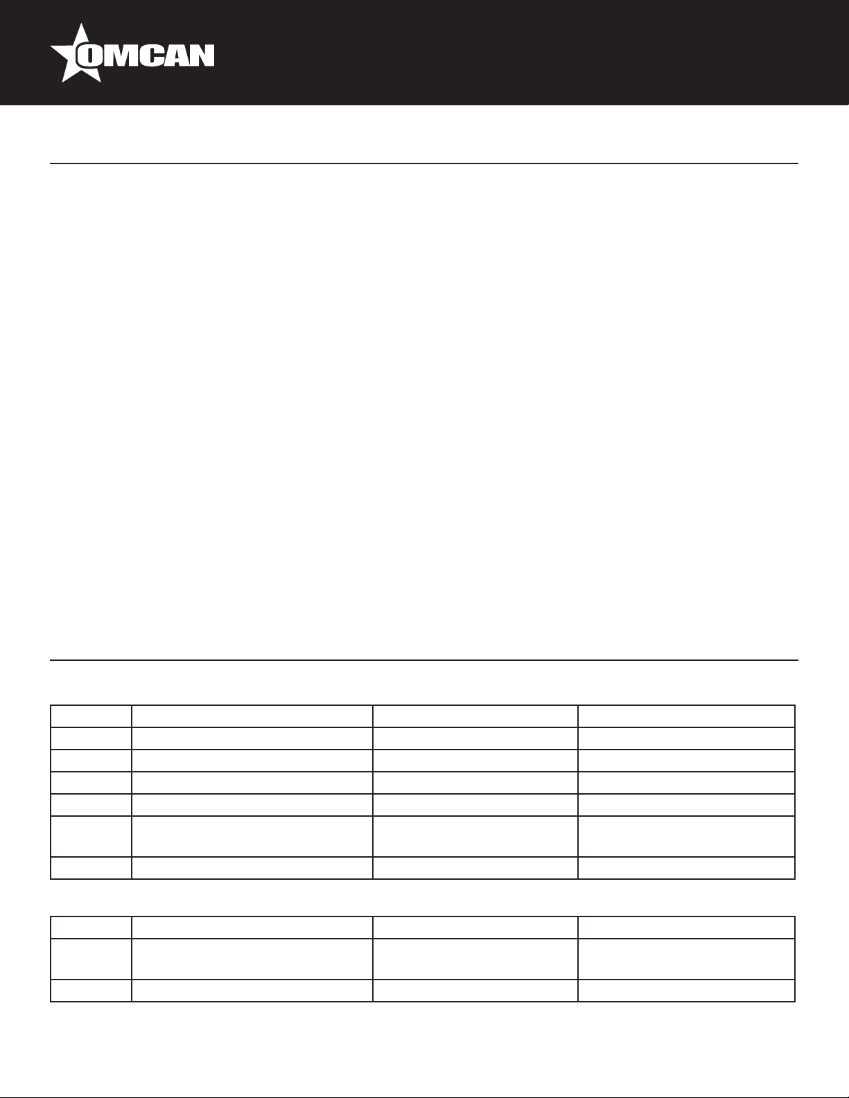
Troubleshooting
Machine does not run.
Step Check If yes, proceed to If no, proceed to
A1 Is the switched turned to on? Turn on A2
A2 Is there power to the machine? Rewire A3
A3 Is the bin full? A4 Take ice out
A4 Is the bin control adjusted? Adjust A5
A5 Is the high pressure safety switch
tripped?
A6 Is the selector switch out? Replace
Machine runs but does not produce ice.
Step Check If yes, proceed to If no, proceed to
B1 Is water running over the
evaporator?
B2 Is the compressor running? B5 B3
A6 Reset clean condenser
The following
troubleshooting chart.
B2
13

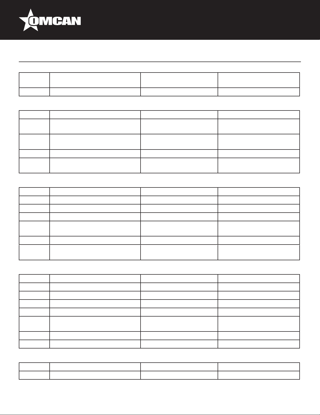
Troubleshooting
B3 Is there power to the
compressor?
B4 Is the switch defective? Replace
B5 Is there water leaking from the
trough?
B6 Is the refrigerant pressure high? Clean the condenser or
B7 Is the refrigerant pressure low? Check for leaks B8
B8 Is there a low side restriction? Repair TXV is defective
Machine produces cloudy or incomplete cubes.
Step Check If yes, proceed to If no, proceed to
C1 Is water running over the
evaporator?
C2 Is the machine level? The incoming water quality
C3 Is the trough water level correct? C6 C4
C4 Is the supply pressure correct? C5 Correct deciency
C5 Is there a water leak? Repair the leak Adjust oat valve
C6 Is the water distribution tube
plugged correctly?
C7 Is the water pump damaged? Replace/Repair pump Clean evaporator spillway
Repair the leak B6
check HGV
C2 C3
is poor.
Clean/replace C7
Check for bad connection or
starting components
B7
Level the unit
Produces proper cubes but is slow in production.
Step Check If yes, proceed to If no, proceed to
D1 Is the unit installed correctly? D2 Correctly install the unit
D2 Is the head pressure too high? D3 Check refrigeration system
D3 Is the condenser clean? Check refrigeration system Clean
Cubes are hollow.
Step Check If yes, proceed to If no, proceed to
E1 Is the water temperature above
100°F?
E2 Is there good ow over the
evaporator?
E3 Is there water leaking from the
purge?
E4 Does the cube adjuster work? Reset cube size E5
E5 Is the evaporator sensor loose? Tighten E6
Correct the temperature E2
E3 Go to section C
Replace valve E4
14
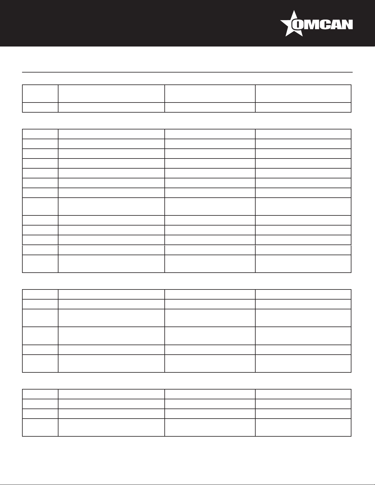
Troubleshooting
E6 Is the evaporator sensor wire
tight?
E7 Is the controller damaged? Replace
Bridge thickness is uneven.
Step Check If yes, proceed to If no, proceed to
F1 Is the water temperature above
100°F?
F2 Is the water running into the bin? Check sections C,D, E or
F3 Is water leaking from the purge? Replace the valve F4
F4 Is the suction pressure high? Check the hot gas valve Recharge and/or check the
Bridge thickness varies with each cycle.
Step Check If yes, proceed to If no, proceed to
G1 Is the water temperature proper? Correctly adjust temperature G2
G2 Is the purge valve leaking? Replace valve G3
G3 Is the hot gas valve damaged? Replace G4
G4 Are sensors connected to the
board?
G5 Is the controller damaged? Replace G6
G6 Is the thermal expansion valve
damaged?
E7 Tight the spade connection to
the board
Correct the temperature F2
F3
check trough for leak
TXV
G5 Tighten spade connections
Replace
Machine does not start producing ice cubes.
Step Check If yes, proceed to If no, proceed to
H1 Does the purge valve work? H6 H2
H2 Is the freeze pattern even? H3 H2
H3 Is the purge valve leaking? Replace H3
H4 Is the compressor failing? Replace H4
H5 Is the system supplied with too
much voltage?
H6 Is the relay defective? Replace H7
H7 Is the board defective? Replace
Machine harvests but returns to ice-making prematurely.
Step Check If yes, proceed to If no, proceed to
I1 Is the manual purge open? Replace purge valve I2
Adjust the voltage Replace TXV
15
Troubleshooting
I2 Is the high temperature safety
switch open?
I3 Is the relay damaged? Replace
Length of harvest is excessive.
Step Check If yes, proceed to If no, proceed to
J1 Is the machine installed correctly? J2 Correct
J2 Is ice forming correctly? J3 Low charge - recharge
J3 Is the suction pressure too low? Replace the hot gas valve J4
J4 Is the evaporator clean? J5 Clean accordingly
J5 Is the ice bridge correct? J6 Go to F or G sections
J6 Is the machine level? J7 Level the unit
J7 Does water run over the
evaporator during harvest?
J8 Is the purge valve leaking? Replace J9
J9 Is the relay damaged? Replace J10
J10 Is the selector switch damaged? Replace
J11 Is the suction pressure damaged? Replace evaporator J12
J12 Is the discharge pressure low
during freezing?
Replace I3
Clean or J11 J8
Ambient temperature is too
low
Replace the hot gas valve
Evaporator gets hot.
Step Check If yes, proceed to If no, proceed to
K1 Is the unit installed correctly? K2 Correctly install the unit
K2 Is the condenser fan turning? K3 Tighten the blade, check the
wires or replace the motor
K3 Are the hot gas valve connections
loose?
K4 Is the machine charged correctly? K5 Charge correctly
K5 Is the controller operating
correctly?
The compressor does not start.
Step Check If yes, proceed to If no, proceed to
L1 Is the condenser dirty? Clean L2
L2 Has the fan stopped or is dirty? Repair/clean L3
L3 Are the wires tight on the
controller?
Tighten all wiring
connections
Replace the hot gas valve Replace the controller board.
L4 Tighten all spade connections.
K4
16
Troubleshooting
L4 Are the compressor starting
components damaged?
L5 Is the controller board damaged? Replace L6
L6 Is the compressor damaged? Replace
Compressor runs but no ice is produced.
Step Check If yes, proceed to If no, proceed to
M1 Is the air vent obstructed? Clear the path M2
M2 Is the condenser dirty? Clean M3
M3 Is the fan turning? M4 Replace fan motor
M4 Is there a refrigerant leak? Add the valve, clean the
M5 Is the TXV or cap tube operating
normally?
M6 Does the ice making mode
convert to harvest?
Machine makes excessive noise.
Step Check If yes, proceed to If no, proceed to
N1 Are the panels loose? Tighten all the screws N2
N2 Is the fan hitting the shroud? Realign N3
N3 Is the fan blade loose? Tighten N4
N4 Is the pump noisy? N5 N6
N5 Is there an object in the propeller? Remove the object Replace the pump
N6 Is the noise from the compressor? Replace the compressor
Replace components L5
M5
refrigerant, x and charge
(replace lter)
M6 Add the valve, clean the
refrigerant, x and charge
(replace lter)
Replace the controller board
ADVANCED COMPONENT TROUBLESHOOTING TECHNIQUES
Refrigerant Cycle and Components
Before diagnosing the refrigeration system, it is very important that the refrigeration charge is correct.
Whenever the refrigeration system has been opened, the lter drier must be replaced and the proper
refrigerant charge must be weighed in.
Refrigerant Pressures
The suction pressure at the beginning of the freeze cycle can vary +/10 psi (.7 bar) depending on operating
conditions. Pressures less than this may indicate an undercharge. The discharge pressure on air cooled units
will vary with ambient conditions. Refrigerant in a gas state is pumped throughout the refrigeration system by
17

Troubleshooting
a hermetic compressor to the condenser. Heat is removed from the refrigerant either by forced air movement
through an air cooled condenser or transferring heat from the refrigerant to water through a water cooled
condenser. The refrigerant changes to a liquid when cooled. The refrigerant in a liquid state passes through a
lter drier. The lter drier traps small amounts of moisture and foreign particles from the system. The lter drier
must be replaced whenever the refrigeration system is opened or if the refrigerant has been completely lost.
Compressor
The compressor runs during the entire cycle. If the valves in the compressor are damaged, the compressor
will be unable to pump refrigerant efciently. Damaged valves may be the result of another problem in the
refrigeration system. When a compressor is replaced it is important that the refrigeration charge be weighed
in and the system checked for proper operation to prevent a repeat failure. An inefcient compressor will
usually have a higher than normal suction pressure at the end of the cycle. The freeze cycle will be longer
than normal and/or the harvest cycle may be excessively long. Check the compressor’s amps 5 minutes into
the freeze cycle. If the amps is less than 70% of rated full amount, the compressor may be inefcient. These
symptoms may also be caused by other problems, therefore it is important to use the troubleshooting charts
when diagnosing a problem. The air condenser is located in the back of the cabinet. Air is pulled through the
condenser by a fan motor and released through the right hand side panel. Under the counter models intake
and discharge air through the front panel. Do not block airow as it will cause premature failure of the machine
and will void the warranty.
Compressor and Start Components
The compressor should run during the entire cycle. If the machine is in the ON position but the compressor is
not running, check the compressor contactor to see if it is connected properly. If the contactor is not connected,
the problem is not with the compressor or the compressor start components. If the contactor is engaged and
there is correct voltage through the contactor, there could be a problem with one of the starting components or
the compressor. It is recommended that the compressor starting components be replaced when replacing the
compressor.
DISCONNECT POWER BEFORE SERVICING!
If the compressor uses an internal overload, be certain that the compressor has cooled and the overload
has reset before diagnosing the compressor. If the compressor is cool and is still not running, check the
compressor motor windings by rst removing the wires at the compressor terminals. With an ohmmeter, check
for continuity between all three terminals, if an open circuit exists between any of the terminals, the compressor
may need to be replaced. Check for continuity from each terminal to the compressor body, if continuity is found
from any terminal to the compressor body, the compressor windings are shorted to ground and the compressor
will need to be replaced. If the compressor appears to be good at this point, it is advisable to use a compressor
analyzer to isolate the compressor from the start components while checking for a locked rotor. If it is not
available, the compressor starting components must be checked. If all starting components are working, check
the amp rating from the terminal of the compressor, making sure proper voltage is supplied to the compressor
and all wiring is properly connected. If the compressor does not start and there is excessive amp rating, (see
locked rotor amps on compressor tag) the compressor has a locked rotor and should be replaced.
18
 Loading...