

Omcan Food Machinery H15Ei Installation Manual
H15•H20•H26•H31•H42•H52
Fillers
Stuffers
Poussoirs
Version 3.5 • Revised October 2006
Kolbenfüllmaschinen
Stopmachines
Pølsestoppere
Insaccatrici
Embutidoras
Illustration: H26p
OPERATING INSTRUCTIONS
Before operating the machine, please read this manual thoroughly.
This manual should be retained for future reference.
MODE D’EMPLOI
Avant la mise en service de cette machine, prière de lire attentivement cette
notice d’utilisation que vous conserverez pour toute référence ultérieure.
BETRIEBSANLEITUNG
Vor Inbetriebnahme der Maschine lesen Sie bitte diese Gebrauchsanleitung
gründlich durch und bewahren Sie sie für später auf.
ENGLISH
FRANÇAIS
DEUTSCH
NEDERLANDS
GEBRUIKSAANWIJZING
Lees deze gebruiksaanwijzing aandachtig door alvorens de machine
in werking te stellen. Bewaar deze handleiding als naslagwerk.
BRUGSANVISNING
Før igangsætning af maskinen bør denne håndbog læses omhyggeligt.
Gem håndbogen for fremtidige forespørgsler.
MANUALE DI ISTRUZIONI
Prima di utilizzare la macchina leggere attentamente questo
manuale e conservarlo per future informazioni.
MANUAL DE INSTRUCCIONES
Antes de utilizar la máquina lea este manual detenidamente
y consérvelo para futuras consultas.
Serial No.: __________
DANSK
ITALIANO
ESPAÑOL

THE 3-DIGIT NUMBERS SHOWN INTHIS PRINTDRAWINGARE NOT VALID FOR ORDERS. PLEASE ORDER PARTS BY USING ONLYTHE DETAILED IN THE ENCLOSED
PARTS LIST AND ONLY THROUGH THE AUTHORIZED DEALER WHO SOLD THE MACHINE. FOR SOME PARTS ADDITIONAL TECHNICAL, ELECTRICAL, DRAWING DETAILS WILL BE
NEEDED.
LES NUMÉROS DE 3 CHIFFRES INDIQUÉS DANS CET ÉCLATÉ NE SONT PAS VALIDES POUR DES COMMANDES DE PIÈCES. POUR CE FAIRE, UTILISEZ UNIQUEMENT LE CODE À
CHIFFRES
PIECES DETAILSTECHNIQUES, ELECTRIQUES,DESSINSCOMPLEMENTAIRES SERONT PRECISES.
DIE SICH IN DIESER ZEICHNUNG BEFINDLICHEN 3 STELLIGEN NUMMERN GELTEN NICHT FÜR BESTELLUNGEN. BESTELLEN SIE BITTE ERSATZTEILE AUSSCHLIEßLICH MITTELS
DES CODES, DER SICH IN DER NACHSTEHENDEN TABELLE BEFINDET. WENDEN SIE SICH DIESBEZÜGLICH BITTE IMMERAN DEN FACHHÄNDLER , BEI DEN SIE DIE
MASCHINE GEKAUFT HABEN.
DE IN DEZE TEKENING VERMELDE 3-CIJFERIGE CODES ZIJN NIET GELDIG VOOR BESTELLINGEN VAN ONDERDELEN. BESTELLINGEN KUNNENALLEEN GEDAAN WORDEN M.B.V.
DE 4-CIJFERIGE CODES VERMELD OP DE TABEL DIE TE VINDEN IS OP DE VOLGENDE PAGINA'S. WENDT U ZICH HIERVOORALTIJD AAN DE DISTRIBUTEUR WAAR U DE MACHINE
GEKOCHT HEEFT. BIJ ENKELE ONDERDELEN ZIJN COMPLETETECHNISCHEEN/OFELEKTRISCHEGEGEVENSMETEVENTUELE TEKENINGEN, ENZ. NODIG.
LOS NÚMEROS DE 3 DÍGITOS INDICADOS EN ESTE DESPIECE NO SON VALIDOS PARA PEDIDOS. LOS PEDIDOS DE REPUESTOS SOLO SE DEBEN HACER CON EL CÓDIGO DE
CIFRAS
PIEZAS SE REQUERIRÁNADEMASCOMPLETOSDETALLES TÉCNICOS, ELÉCTRICOS, DIBUJO, ETC.
COMPRIS DANS LATABLE CI-JOINTE. FAITES VOS COMMANDES EXCLUSIVEMENTÀ TRAVERS DU DISTRIBUTEUR QUI VOUSA VENDU LA MACHINE. POUR CERTAINES
4 ZIFFRIGEN
PRECISADO EN LA TABLA ADJUNTAA LAS PAGINAS SIGUIENTES Y EXCLUSIVAMENTE A TRAVÉS DEL DISTRIBUIDOR QUE LE HAYA VENDIDO LA MÁQUINA. EN ALGUNAS
4-DIGITS CODE
4
4
H-203
H-200
H-201
H-204
H-205 (7032)
H-206 (0136)
H-207 (2585)
H-251 (7316)
H-208
H-209
H-210
H-212
H-202 H-206
H-250
H-217
H-215
H-249H-260
H-242
H-247 (7060)
H-246 (7029)
H-245 (0109)
H-248
H-244
H-268
H-243
H-241
H-240
H-239
H-238
Updated
01/2006
H-237
H-236 (2589)
H-261
H-235 (2592)
H-234 (2680)
H-232 (2467)
H-259 (2403)
H-231
H-230 (0105)
H-229 (0104)
H-252 (3402)
H-258 (2278)
H-255
H-256 (7318)
H-254 (7319)
H-253 (7320)
H-267 (3435)
H-233 (2012)
H-228 (2353)
H-213
H-263 (0086)
H-264 (2683)
H-265 (2580)
H-266 (2590)
H-218
H-214
H-219
H-220
H-222 (2034)
H-221 (2033)
H-227
H-211 (2039)
H-226
H-225 (0063)
H-224 (0064)
H-223

TAPA ALUMINIO DEPOSITO
CARNE (MODELOS P)
TAPA ALUMINIO DEPOSITO
CARNE (MODELOS E)
TAPA ACERO INOX
DEPOSITO CARNE
COJINETE PLASTICO TAPA
ALUMINIO DEPOSITO MASA
E-DESMONTABLE
ALUMINIUM DEKSEL (P-
MODELLEN)
ALUMINIUM DEKSEL (E-
MODELLEN)
RVS DEKSEL
LAGERBUS PLASTIC
DEKSELAS ALUMINIUM E-
MOD AFNEEMBARE CILINDER
ALUMINIUM DECKEL (NUR P-
MODELLE)
ALUMINIUM DECKEL (NUR E-
MODELLE)
DECKEL EDELSTAHL
ROSTFREI
PLASTIK KUGELLAGER
ALUMINIUM DECKEL E-MOD
ABNEHMBARER ZYLINDER
COJINETE BRONCE TAPA
ALUMINIO DEPOSITO MASA
P-FIJO
COJINETE BRONCE TAPA
ACERO INOX DEPOSITO
MASA P-FIJO
TUERCA PORTAEMBUDOS
ALUMINIO ABIERTA
LAGERBUS BRONS
DEKSELAS ALUMINIUM P-
MODEL VASTE CILINDER
LAGERBUS BRONS
DEKSELAS RVS P-MODEL
VASTE CILINDER
AFSLUITMOER ALUMINIUM,
OPEN
BRONZE KUGELLAGER
ALUMINIUM DECKEL P-MOD
FESTSTEHENDER ZYLINDER
BRONZE KUGELLAGER
DECKEL EDROST P-
MODDELLE FESTSTEHENZYL
VERSCHLUßMUTTER
ALUMINIUM, OFFEN
TUERCA PORTAEMBUDOS
ACERO INOX, SIN RANURA
AFSLUITMOER RVS,
GESLOTEN
VERSCHLUßMUTTER
EDELSTAHL GESCHLOSSEN
HERRADURA INOX TAPA
ALUMINIO MODELO E
HERRADURA INOX TAPA
ALUMINIO MODELO P
PALANCA APERTURA TAPA
HOEFIJZERVORMIGE RVS
VERSTEVIGING E-MODEL
HOEFIJZERVORMIGE RVS
VERSTEVIGING P-MODEL
DEKSELHENDEL ZONDER
DECKELANSCHLAG FÜR
ALU.-DECKEL E-MODELLE
DECKELANSCHLAG FÜR
ALU.-DECKEL P-MODELLE
DECKELGRIFF OHNE GRÜN
SIN POMO PLASTICO VERDE
POMO ITAL PLASTICO VERDE
PALANCA TAPA
FUNDA RODILLERA GOMA
VERDE
EJE VERTICAL ACERO INOX
RODILLERA MOD. P EXCEPTO
H42/H52
RODE KNOP
DEKSELKNOP GROEN ITAL
RUBBEREN KNIEHENDEL
GROEN
VERTICALE KNIEHENDELAS
RVS MOD. P EXC H42/H52
KNOPF
GRÜN DECKELGRIFFKNOPF
AUS PLASTIK ITAL
GUMI-KNIEHEBEL GRÜN
VERTIKALER KNIEHEBEL-
SCHAFT, EDELS. ROSTFREI
MOD. P EXC H42/H52
EJE VERTICAL ACERO INOX
RODILLERA MOD. E+H42/H52
COJINETE BRONCE GIRO
RODILLERAS HP EXCEPTO
H42/H52
COJINETE BRONCE GIRO
RODILLERAS HE Y H42/H52
VERTICALE KNIEHENDELAS
RVS MOD. E+H42/H52
LAGERBUS BRONS
KNIEHENDEL VOOR HP
MODELLEN BEHALVE
H42/H52
LAGERBUS BRONS
KNIEHENDEL VOOR HE EN
H42/H52 MODELLEN
VERTIKALER KNIEHEBEL-
SCHAFT, EDELSTAHL
ROSTFREI MOD. E+H42/H52
KUGELLAGER BRONZE
KNIEHEBEL FÜR HP
MODELLEN AUSSER H42/H52
KUGELLAGER BRONZE
KNIEHEBEL FÜR HE UND
H42/H52 MODELLEN
COUVERCLE ALUMINIUM
(SEULEMENT MODELES P)
COUVERCLE ALUMINIUM
(SEULEMENT MODELES E)
PARTS LIST LISTE DE PIÈCES TEILELISTE ONDERDELENLIJST LISTA PIEZAS
ALUMINUM LID (ONLY P
MODELS)
ALUMINUM LID (ONLY E
MODELS)
S/S LID COUVERCLE ACIER INOX
H52
COUSSINET PLASTIQUE
COUVERCLE ALUMINIUM
MODELE E-DÉMONTABLE
COUSSINET BRONZE
COUVERCLE ALUMINIUM
MODELE P-FIXE
COUSSINET BRONZE
PLASTIC BEARING FOR
ALUMINUM LID E-
REMOVABLE BARREL
MODEL
BRONZE BEARING FOR
ALUMINUM LID P-FIXED
BARREL MODEL
BRONZE BEARING FOR S/S
COUVERCLE ACIER INOX
MODELE P-FIXE
ÉCROU ALUMINIUM RANURE
OUVERTE PORTE-EMBOUTS
ÉCROU ACIER INOX PORTE-
EMBOUTS, FERMÉE
LID P-FIXED BARREL
MODEL
ALUMINUM HORN/NOZZLE
LOCKING NUT, OPEN SLOT
S/S HORN/NOZZLE
LOCKING NUT, W/OUT
FER COUVERCLE
SLOT
HORN/NOZZLE, ALL S/S EMBOUT, TOUT ACIER INOX FÜLLROHR, GANZ ROSTFREI WORSTHOORN RVS EMBUDO, ACERO INOX
S/S HORSESHOE FOR
ALUMINIUM MODELE E
FER COUVERCLE
ALUMINIUM MODELE P
LEVIER COUVERCLE SANS
POIGNEE PLASTIQ VERT
POIGNEE PLASTIQUE POUR
LEVIER COUVERCLE ITAL
CAOUTCHOUC VERT
ALUMINUM LID E MODEL
S/S HORSESHOE FOR
ALUMINUM LID P MODEL
LID LEVER WITHOUT
GREEN PLASTIC KNOB
GREEN PLASTIC ITAL
KNOB FOR LID LEVER
GREEN RUBBER KNEE
GENOUILLERE
AXE VERTICAL
GENOUILLERE ACIER INOX
MOD. P SAUF H42/H52
AXE VERTICAL
GENOUILLERE ACIER INOX
MOD. E+H42/H52
LEVER
VERTICAL KNEE LEVER
SHAFT P-MODEL, S/S
EXCEPT H42/H52
VERTICAL KNEE LEVER
SHAFT E+H42/H52-MODEL,
S/S
COUSSINET BRONZE AXE
GENOUILLERE POUR
MODELES HP SAUF H42/H52
COUSSINET BRONZE AXE
GENOUILLERE POUR
MODELES HE ET H42/H52
KNEE LEVER BRONZE
BEARING FOR HP MODELS
EXCEPT H42/H52
KNEE LEVER BRONZE
BEARING FOR HE AND
H42/H52 MODELS
H15 H20 H26 H31 H42
H200 7008 7008 7005 - - -
H200 7535 - 7536 - - -
H200 - - 7023 7299 7143 7568
H201 7258 - 7257 - - -
H201 0052 0052 0027 - - -
H201 - - 7259 7517 7262 7571
H202 7048 7048 7048 - - -
H202 - - 7025 7025 7025 7025
H203 Div Div Div Div Div Div
H204 7317 - 7317 - - -
H204 7101 7101 7101 - - -
H205 7032 7032 7032 7032 7032 7032
H206 0136 0136 0136 0136 0136 0136
H207 2585 2585 2585 2585 2585 2585
H208 7445 7445 7445 7445 - -
H208 7446 - 7446 - 7446 7446
H209 7454 7454 7454 7454 - -
H209 2859 - 2859 - 2859 2859
2

JUNTA COMPUERTA GOMA
VERDE
MICROINTERRUPTOR (SOLO
MODELOS A)
AFDICHTINGSRUBBER
GROEN VOOR ACHTERPLAAT
MIKRO-SCHAKELAAR
MODELLEN A
(AUTOMATISCH)
GRÜN DECKELDICHTUNG
FÜR MASCHINENGEHÄUSE
INNERER MIKROSCHALTER
CROUZET (A-MODELLE
AUTOMATISCH)
CAJA AISLANTE CUADRO
VEILIGHEIDS-ELEKTRADOOS
ELECTRICO
CONTACTOR
TELEMECANIQUE
CILINDRO HIDRAULICO
COMPLETO
PATA ANTIVIBRATORIA GOMA
KUNSTSTOF
MAGNEETSCHAKELAAR
TELEMECANIQUE
COMPLETE HYDRAULISCHE
CILINDERBUS
SCHALTGEHÄUSE
SCHÜTZ TELEMECHANISCH
KOMPLETTE
KOLBENSTANGENEINHEIT
ANTI-VIBRATIONS FUß, GRÜN
VERDE
SOPORTE ANTIVIBRATORIO
MOTOR, GOMA NEGRA
ANTIVIBRATIEPOOT
ANTIVIBRATIEBASIS MOTOR
GUMMI
ANTI-VIBRATIONS STÜTZE
MOTOR, SCHWARZ GUMMI
JUNTA BOMBA HIDRAULICA
CRUCETA ACCIONAMIENTO
ELEKTROMOTOR-POMP
VERPAKKING
ELEKTROMOTOR-POMP
VERBINDUNGSSTÜCK
MOTOR-BOMBA
KOPPELING
MOTOR- PUMPE
BANCADA INFERIOR
BASIS/VOETSTUK/
POMO Y EJE SUELTOS
REGULADOR
PRENSAESTOPAS
MANGUERA ELECTRICA
CONTRATUERCA
PRENSAESTOPAS
ONDERFRAME
KNOP EN AS VAN HET DRUK-
SNELHEIDS-REGELVENTIEL
KABELSTOP
SCHROEFDRAAD
BEVESTIGINGSMOER
KABELSTOP
NUR ROTER KNOPF +
SCHAFT FÜR
REGULIERVENTIL
ZUGENTLASTUNG
ETIQUETA REGULACION
PRESIÓN
DISTRIBUIDOR HIDRAULICO
COMPLETO
HANDVAT ASA TRANSPORTE
STICKER DRUK- SNELHEIDS-
REGELVENTIEL
COMPLEET STUURVENTIEL
TRANSPORTGRIFF
EDELSTAHL ROSTFREI
AUFKLEBER
DRUCKREGULIERVENTIEL
DRUCKREGELVENTIL
KOMPLETT
AUFKLEBER ÖL STICKER OLIE ETIQUETA TAPON ACEITE
JOINT PORTE SOCLE
CAOUTCHOUC VERT
MICRO-INTERRUPTEUR
INTERNE CROUZET
PARTS LIST LISTE DE PIÈCES TEILELISTE ONDERDELENLIJST LISTA PIEZAS
GREEN RUBBER GASKET
PANEL
INTERNAL CROUZET
MICRO-SWITCH (ONLY A-
H52
(MODELES A-AUTOMAT)
AUTOMATIC MODELS)
OIL FILTER FILTRE D’HUILE ÖLFILTER OLIEFILTER FILTRO ACEITE
COFFRET ELECTRIQUE
PLASTIQUE
OIL FILTER COVER COUVERCLE FILTRE HUILE DECKEL ÖLFILTER DEKSEL OLIEFILTER TAPA FILTRO ACEITE
GREEN PLASTIC WHEEL ROUE PLASTIQUE VERT GRÜN PLASTIKRAD WIEL PLASTIC GROEN RUEDA PLASTICO VERDE
PLASTIC ELECTRIC
SWITCHBOARD BOX
CONTACTEUR
TELEMECANIQUE
VERIN HYDRAULIQUE
COMPLET
PIED ANTI-VIBRATION
CAOUTCHOUC VERT
BASE CAOUTCHOUC NOIR
CONTACTOR
TELEMECANIQUE
AIR EXTRACTION FAN VENTILATEUR EXT RAIR VENTILATOR LUCHTVENTILATOR VENTILADOR EXTRACC AIRE
COMPLETE HYDRAULIC
CYLINDER
GREEN RUBBER ANTI-
VIBRATION FOOT
BLACK RUBBER ANTI-
ANTI-VIBRATION MOTEUR
VIBRATION MOTOR SUPP
HYDRAULIC PUMP POMPE D’HUILE ÖLPUMPE HYDRAULISCHE POMP BOMBA HIDRAULICA
ACCOUPLEMENT MOTEUR-
POMPE
MOTOR-PUMP GASKET JOINT MOTEUR-POMPE DICHTUNG MOTOR-ÖLPUMPE
MOTOR-PUMP COUPLING
ELECTRIC MOTOR MOTEUR ELECTRIQUE ELEKTROMOTOR ELEKTROMOTOR MOTOR ELECTRICO
MACHINE FRAME SOCLE MACHINE MASCHINENGEHÄUSE
SEULEMENT POIGNEE
ROUGE + AXE REGULATEUR
PRESSE-ETOUPE FIL
ALIMENTATION
RED KNOB + SHAFT ONLY
(PRESSURE CONTROL)
SUPPLY CORD GROMMET
POIGNEE TRANSPORT
GROMMET NUT ÉCROU PRESSE-ETOUPE GEGENMUTTER
ACIER INOX
AUTOCOLLANT
REGULATEUR DE PRESS
DISTRIBUTEUR
HYDRAULIQUE COMPLET
S/S TRANSPORT HANDLE
PLASTIC PRESSURE
CONTROL LABEL
COMPLETE HYDRAULIC
DIRECT CONTROL VALVE
AUTOCOLLANT ENTREE
HUILE
OIL INPUT LABEL
H15 H20 H26 H31 H42
H210 2049 3302 2017 2017 3305 3447
H211 2039 2039 2039 2039 2039 2039
H212 2035 2035 0079 0079 0079 0079
H213 7327 7327 7327 7327 7327 7327
H214 2014 2014 2014 2014 2290 2290
H215 0758 0758 0758 0758 0758 0758
H217 Div Div Div Div Div Div
H219 2019 2866 2019 2019 2019 2019
H220 0038 2610 0012 0012 0803 0803
H221 2033 2033 2033 2033 2528 2528
H222 2034 2034 2034 2034 2034 2034
H223 0037 0037 0011 0011 0855 0855
H224 0064 0064 0064 0064 0064 0064
H225 0063 0063 0063 0063 0063 0063
H226 Div Div Div Div Div Div
H227 Div 2082 Div 2009 2282 3437
H228 2353 2353 2353 2353 2353 2353
H229 0104 0104 0104 0104 0104 0104
H230 0105 0105 0105 0105 0105 0105
H231 0188 0188 0188 0188 7310 7310
H232 2467 2467 2467 2467 2467 2467
H233 2012 2012 2012 2012 2012 2012
H234 2680 2680 2680 2680 2680 2680
3

TUBO ENTRADA ACEITE
PLASTICO VERDE
TAPON PLASTICO VERDE
ACEITE CON VARILLA
TUERCA ACERO INOX
VASTAGO TAPA (MODELOS
P)
PIJP OLIETOEVOER GROEN
PLASTIC
DOP GROEN PLASTIC MET
OLIEMEETSTAAF
MOER RVS VOOR DEKSEL (P-
MODELLEN)
GRÜN ÖLROHR FÜR
ÖLEINLAß
GRÜN PLASTIK-STOPFEN MIT
ÖLMEßSTAB
MUTTER EDELSTAHL
DECKELBOLZEN (P-
MODELLE)
ARANDELA ACERO INOX
VASTAGO TAPA (MODELOS
P)
DEPOSITO CARNE P-FIJO
DEPOSITO CARNE E-
DESMONTABLE
RVS SLUITRING VAN
AANSLAGAS (P-MODELLEN)
MENGSELCILINDER P-MODEL
VASTE
MENGSELCILINDER E-MODEL
AFNEEMBAAR
UNTERLEGSCHEIBE
EDELSTAHL FÜR BOLZEN (P-
MODELLE)
BRÄTZYLINDER P-MODELLE
FESTSTEHEND
BRÄTZYLINDER E-MODELLE
ABNEHMBAR
DISCO PROTECTOR FONDO
DEPOSITO (MODELOS P)
SOMBRERETE PROTECTOR
FONDO DEPÓSITO
(MODELOS E)
RVS CILINDERBODEM
AFDEKPLAAT (P-MODELLEN)
RVS CILINDERBODEM
AFDEKPLAAT (E-MODELLEN)
ZYLINDERBODEN-
SCHUTZDECKEL (P-
MODELLE)
ZYLINDERBODEN-
SCHUTZDECKEL (E -
MODELLE)
JUNTA TAPA DEPÓSITO P
SILICONA VERDE PERFIL
RVS BOUT TORNILLO ACERO INOX
DEKSELDICHTINGSRING
VOOR P-MODELLEN
EDELSTAHLSCHRAUBEN
BEFESTIGUNG
DECKELDICHTUNG FÜR P-
MODELLE ZYLINDER (3-
REDONDO (PAQUETE DE 3)
JUNTA TAPA-DEPÓSITO E
GOMA VERDE PERFIL
RECTANGULAR (PAQUETE
DE 3)
VASTAGO ACERO INOX GIRO
TAPA HP
CILINDER (PAKKETJE VAN 3)
DEKSELDICHTINGSRING
VOOR E-MODELLEN
CILINDER (PAKKETJE VAN 3)
RVS AANSLAGAS VOOR
DEKSEL (P-MODELLEN)
PACKUNG)
DECKELDICHTUNG
RECHTECKIG GUMMI GRÜN
NUR FÜR E- MODELLE
ZYLINDER (3-PACKUNG)
EDELSTAHL BOLZEN FÜR
DECKEL (P-MODELLE)
CONJUNTO LLAVE-TORNILLO
EXTRACTOR DE PISTON
JUNTA TÓRICA PISTON
(PAQUETE DE 4/2 UD)
JUNTA TÓRICA TORNILLO
CIERRE PISTON
ZUIGERSLEUTEL
SCHRAUBE O-RING O-RING ZUIGERSCHROEF
KOLBENABZIEH-
VORRICHTUNG
TUERCA CIERRE TAPA (SOLO
ZUIGERDICHTINGSRING
(PAKKETJE VAN 4/2)
DEKSEL SLUITSCHROEF
KOLBEN O-RING ( 4/2-
PACKUNG)
DECKEL
BEFESTIGUNGSSCHRAUBE
MOD E)
(ALLEEN E-MODELLEN)
(NUR E-MODELLE)
TUBE PLASTIQUE VERT
ENTREE HUILE
PARTS LIST LISTE DE PIÈCES TEILELISTE ONDERDELENLIJST LISTA PIEZAS
GREEN PLASTIC OIL INPUT
TUBE
H52
BOUCHON PLASTIQUE
REMPLISSAGE HUILE AVEC
TIGE NIVEAU
ÉCROU ACIER INOX
BOULON COUVERCLE
(MODELES P SEULEMENT)
RONDELLE ACIER INOX
BOULON COUVERCLE
PLASTIC OIL DRAIN PLUG
WITH LEVEL BAR
S/S HEX NUT FOR LID
BOLT (P MODELS ONLY)
S/S WASHER FOR LID
BOLT (P MODELS ONLY)
(MODELES P)
CYLINDRE VIANDE E-
DEMONTABLE
DISQUE INOX PROTECTION
FIXED P MEAT BARREL CYLINDRE VIANDE P- FIXE
REMOVABLE E MEAT
BARREL
S/S BARREL BOTTOM
FOND CYLINDRE (MODÈLES
P SEULEMENT)
CHAPEAU INOX
PROTECTION FOND
CYLINDRE (MODÈLES E)
PROTECTION DISC (P
MODELS ONLY)
S/S BARREL BOTTOM
PROTECTION HAT (E
MODELS ONLY)
S/S FIXING SCREW VIS ACIER INOX FIXATION
JOINT COUVERCLE POUR
CYLINDRE MODELES P
(PAQUET DE 3 UNITÉS)
JOINT RECTANGULAIRE
CAOUTCHOUC VERT
COUVERCLE-CYLINDRE
VIANDE MODELES E
SEULEMENT (3 UNITÉS)
PIVOT ACIER INOX
COUVERCLE HP
LID GASKET FOR P
MODELS BARREL ONLY
(PACKAGE OF 3)
GREEN RUBBER
RECTANGULAR LID
GASKET FOR E MODELS
REMOVABLE BARREL
ONLY (PACKAGE OF 3)
S/S LID BOLT MODELS HP
7039 7142 7142
7021
7039
JOINT TORIQUE VIS CENTRE
PISTON
CLE ET VIS D’EXTRACTION
DU PISTON
ALUMINUM PISTON PISTON ALUMINIUM KOLBEN ALUMINIUM ZUIGER ALUMINIUM PISTON ALUMINIO
S/S PISTON PISTON ACIER INOX KOLBEN EDELSTAHL ROSTF ZUIGER RVS PISTON ACERO INOX
PISTON LOCKING BOLT O-
RING
PISTON LOCK BOLT SCRE VIS FIXATION CENTR PISTO KOLBENSCHRAUBE ZUIGERSCHROEF TORNILLO CIERRE PISTON
PISTON REMOVING
WRENCH WITH SCREW
JOINT TORIQUE PISTON
(PAQUET DE 4/2 UNITÉS)
ÉCROU FERMETURE
COUVERCLE (SEULEMENT
MODELES E)
PISTON O-RING (PACKAGE
OF 4/2 UNITS)
LID CLOSING NUT (ONLY E
MODELS)
H15 H20 H26 H31 H42
H235 2592 2592 2592 2592 2592 2592
H236 2589 2589 2589 2589 2589 2589
H237 0048 0048 0022 0022 0810 0810
H238 0049 0049 0023 0023 0811 0811
H239 7161 7265 7162 7266 7141 7567
H239 2043 - 2011 - - -
H240 2044 2044 2032 2373 0819 3446
H240 2047 - 2015 - - -
H241 2025 2025 2025 2025 0823 0823
H242 6230 6230 6231 6093 6232 6240
H242 6233 - 6234 - - -
H243 7026 7026
H244 7009 7009 7006 - - -
H244 - - 7024 7333 7144 7569
H245 0109 0109 0109 0109 0109 0109
H246 7029 7029 7029 7029 7029 7029
H247 7060 7060 7060 7060 7060 7060
H248 6235 6235 6236 6238 6237 6239
H249 7305 - 7305 - - -
4

BARRA LATERAL FIJACION
DEPOSITO (SOLO MOD E)
CILINDER
BEVESTIGINGSSTAAF
(ALLEEN E-MODELLEN)
ZYLINDER
BEFESTIGUNGSSTANGE
(NUR FÜR E-MODELLE)
HORIZONTALER
INTERRUPTOR MANUAL 0-1
CON MANETA NEGRA (SOLO
MODELOS i)
AS VAN KNIEHENDEL EJE HORIZONTAL RODILLERA
SCHAKELAAR 0-1 MET
ZWARTE KNOP (ALLEEN i-
MODELLEN)
KNIEHEBELSCHAFT,
EDELSTAHL ROSTFREI
INNERER 0-1
DREHSCHALTER MIT
SCHWARZEN KNOPF (NUR i)
VARILLA ROSCADA PALANCA
M8
ACCIONADOR RODILLERA
HORQUILLA PALANCA
ARTICULACIÓN RODILLERA
STANG KNIEHENDEL MET M8-
KNIEHEBELSCHAFT MIT M8-
DISTRIBUIDOR
SCHROEFDRAAD
ACTIVERINGSSTAAF VOOR
REGELVENTIEL
GEWINDE
AKTIVIERUNGSSCHAFT FÜR
REGELVENTIL
PALANCA TUERCA CIERRE
TAPA MODELOS E SOLO, SIN
POMO VERDE
JUNTA CIRCULAR INFERIOR
DEPOSITO, COLOR VERDE
(SOLO MOD P)
ARANDELA
METALOPLÁSTICA
HIDRÁULICA 3/8” VACIADO
STAAF MOER SLUITEN VAN
DEKSEL (ALLEEN E-MOD.),
ZONDER RODE KNOP
LAGE RONDE CYLINDER-
DICHTINGSRING, GROEN
(ALLEEN P-MOD.)
HYDRAULISCHE PLASTIC
SLUITRING 3/8”, LEDIGING
GRIFF OHNE GRÜN KNOPF
FÜR SCHLIEßMUTTER, NUR
E-MODELLE
UNTERE RUNDE ZYLINDER-
DICHTUNG, GRÜN (NUR FÜR
P-MODELLE)
HYDRAULISCHE PLASTIK-
UNTERLEGSCHEIBE 3/8”,
AUSLAUF
ARANDELA PLANA GOMA
NEGRA VACIADO
ARANDELA PLANA ESPECIAL
ACERO INOX VACIADO
SOPORTE MICROINTERRUPT
(SOLO MODELOS P)
CASQUILLO ROSCADO
PISTON ALUMINIO
VLAKKE RUBBEREN
SLUITRING ZWART, LEDIGING
VLAKKE SLUITRING
SPECIAAL RVS, LEDIGING
HOUDER MICROSCHAKEL.
(ALLEEN P MOD.)
HULS SCHROEFDRAAD
ALUMINIUM ZUIGER
FLACHE UNTERLEGSCHEIBE
SCHWARZER GUMMI,
AUSLAUF
FLACHE UNTERLEGSCHEIBE
EDELST ROSTF, AUSLAUF
HALTER MIKROSCHALTER
(NUR FÜR P MODELLE)
HÜLSE ALUMINIUM KOLBEN
BARRE LATERAL FIXATION
CYLINDRE (SEULEMENT
MODELES E)
AXE HORIZONTAL
GENOUILLERE ACIER INOX
INTERRUPTEUR MANUEL 0-1
PARTS LIST LISTE DE PIÈCES TEILELISTE ONDERDELENLIJST LISTA PIEZAS
LATERAL BARREL BAR
(ONLY E MODELS)
HORIZONTAL S/S KNEE
LEVER AXLE
MANUAL SWITCH 0-1 WITH
H52
AVEC BOUTON NOIR
(SEULEMENT MODELES i)
BLACK KNOB (ONLY i
MODELS)
FORK KNEE LEVER FOURCHE GENOUILLERE KNIEHEBELGABEL VORK VAN KNIEHENDEL
TIGE GENOUILLERE
KNEE LEVER BAR TIGE GENOUILLERE KNIEHEBEL SCHAFT KNIEHENDEL STAAF ACCIONADOR RODILLERA
FILETAGE M8
TIGE ACTIONNEMENT
DISTRIBUTEUR HYDRAULIQ
KNEE LEVER THREAD M8
HYDRAULIC CONTROL
ACTION BAR
LEVIER ÉCROU FERMETURE
SANS POIGNEE VERT,
SEULEMENT MODÈLES E
PRESSURE GAUGE P MANOMÈTRE DE PRESSION DRUCKMANOMETER MANOMETER MANÓMETRO
PRESSURE GAUGE HOSE CONDUIT MANOMÈTRE MANOMETERLEITUNG LEIDING MANOMETER LATIGUILLO MANOMETRO
LID CLOSING NUT LEVER
WITHOUT GREEN KNOB, E
MODELS ONLY
JOINT CIRCULAIRE
INFÉRIEUR CYLINDRE,
COULEUR VERT
(SEULEMENT MODÈLES P)
RONDELLE HYDRAULIQUE
METALO-PLASTIQUE 3/8”,
VIDANGE
INFERIOR CIRCULAR
BARREL RUBBER GASKET,
GREEN (ONLY FOR P
MODELS)
HYDRAULIC METAL-
PLASTIC WASHER 3/8”,
EMPTYING
RONDELLE PLATE GOMME
NOIRE, VIDANGE
RONDELLE PLATE
SPÉCIALE ACIER IN, VIDAN
SUPPORT MICROINTERR
(SEULEMENT MODÈLES P)
PLANE BLACK RUBBER
WASHER, EMPTYING
SPECIAL PLANE S/S
RUBBER, EMPTYING
OIL EMPTYING PLUG BOUCHON VIDANGE HUILE ÖLWECHSELSTOPFEN OLIE-LEDIGING DOP TAPÓN VACIADO ACEITE
MICRO SWITCH HOLDER
(ONLY FOR P MODELS)
ANNEAU FILETAGE PISTON
ALUMINIUM
RING, THREADED
ALUMINIUM PISTON
H15 H20 H26 H31 H42
H250 7251 - 7253 - - -
H251 7316 7316 7316 7316 7316 7316
H252 3402 3402 3402 3402 3402 3402
H253 7320 7320 7320 7320 7320 7320
H254 7319 7319 7319 7319 7319 7319
H255 7330 7330 7331 7331 7332 7572
H256 7318 7318 7318 7318 7318 7318
H258 2278 2278 2278 2278 2278 2278
H259 2403 2403 2403 2403 2403 2403
H260 7322 - 7322 - - -
H261 2398 2398 2399 2468 2537 3449
H263 0086 0086 0086 0086 0086 0086
H264 2683 2683 2683 2683 2683 2683
H265 2580 2580 2580 2580 2580 2580
H266 2590 2590 2590 2590 2590 2590
H267 3435 3435 3435 3435 3435 3435
H268 7065 7065 7065 - - -
5

SAMPLE OF
CE
DECLARATION OF CONFORMITY
TALSA as manufacturer, declares that the filler/stuffer model Hxx: is in conformity with the following requirements:
- European Union Machinery Directive 98/37/EC.
- European Union Low Voltage Directive 73/23/EC.
- European Union Electromagnetic Compatibility Directive 89/336/EC.
- EN 60204-1:1997: Safety of Machinery, Electrical Equipment of Machines.
- EN 292-1:4/1993 and EN292-2/A1:2/1996: Safety of Machinery; concepts, principles.
- EN 1672-2:12/1994: Basic Concepts for Food Processing Machinery; part 2: Hygiene Requirements.
- EN 50081-2:1992 and EN 50082-2:1996 Electromagnetic Compatibility EMC.
- prEN 12463:2/1999: Safety and Hygiene Requirements for Fillers/Stuffers.
EXEMPLE DE DECLARATION DE CONFORMITÉ
CE
TALSA comme fabricant, déclare que le poussoir Talsa Hxx répond aux prescriptions suivantes :
- Directive de Machines de l'Union Européenne 98/37/CEE.
- Directive de Basse Tension de l'Union Européenne 73/23/CEE.
- Directive de Compatibilité Electromagnétique de l'Union Européenne 89/366/CEE.
- EN 60204-1 : 1997 : Sécurité des Machines, Equipement Électrique des Machines.
- EN 292-1 : 4/1993 et EN292-2/A1 : 2/1996 : Sécurité des Machines; concepts, principes.
- EN 1672-2 : 12/1994 : Prescriptions relatives à l'Hygiène en Machines Alimentaires.
- EN 50081-2 : 1992 et EN 50082-2 : 1996 : Compatibilité Electromagnetique EMC.
- prEN 12463 : 2/1999 : Sécurité et Hygiène pour Poussoirs.
BEISPIEL -KONFORMITÄTSERKLÄRUNG
CE
TALSA gibt als Hersteller, die Erklärung ab, daß die Kolbenfüller Hxx entspricht den nachfolgend aufgeführten Anforderungen:
- Richtlinie über Maschinen 98/37/EG.
- Richtlinie über Niederspannung 73/23/EG.
- Richtlinie über Elektromagnetische Verträglichkeit 89/366/EG.
- EN 60204-1:1997: Sicherheit von Maschinen, Elektrische Ausrüstung von Maschinen.
- EN 292-1:4/1993 und EN292-2/A1:2/1996: Sicherheit von Maschinen; Grundbegriffen und Prinzipe.
- EN 1672-2:12/1994: Hygieneanforderungen für Nahrungsmittelmaschinen.
- EN 50081-2:1992 und EN 50082-2:1996: Elektromagnetische Verträglichkeit EMV.
- prEN 12463:02/1999: Sicherheits- und Hygieneanforderungen von Füllmaschinen.
VOORBEELD VERKLARING VAN OVEREENSTEMMING
CE
TALSA als fabrikant, verklaart hierbij dat de Stopmachine/Vulvus Hxx voldoet aan de volgende eisen:
- Richtlijn van Machines van de Europese Unie 98/37.
- Richtlijn over laagspaning van de Europese Unie 73/23/EG.
- Richtlijn over elektromagnetische compatibiliteit van de Europese Unie 89/336/EG.
- EN 60204-1:1997: Veiligheid van machines, elektrische inrichtingen van machine.
- EN 292-1:4/1993 en EN292-2/A1:2/1996: Veiligheid van machines, basisbegrippen en -principes.
- EN 1672-2:12/1994: Basisbegrippen voor voedingsverwerkingmachines; deel 2: Eisen inzake hygiëne.
- EN 50081-2:1992 een EN 50082-2:1996: elektromagnetische compatibiliteit EMC.
- prEN 12463:2/1999: Eisen inzake veiligheid en hygiëne voor Vulbussen.
EJEMPLO DE DECLARACION DE CONFORMIDAD
TALSA como fabricante, declara que la embutidora Hxx es conforme con los siguientes requisitos:
- Directiva de Máquinas de la Unión Europea 98/37/CEE.
- Directiva de Baja Tensión de la Unión Europea 73/23/CEE.
- Directiva de Compatibilidad Electromagnética de la Unión Europea 89/336/CEE.
- EN 60204-1:1997: Seguridad de las Máquinas, Equipo Eléctrico de las Máquinas.
- EN 292-1:4/1993 y EN292-2/A1:2/1996: Seguridad de las Máquinas; conceptos, principios.
- EN 1672-2:12/1994: Requisitos sobre Higiene en Maquinaria para Productos Alimentarios.
- EN 50081-2:1992 y EN 50082-2:1992: Compatibilidad electromagnética EMC.
- prEN 12463:2/1999: Requisitos sobre Seguridad e Higiene en Embutidoras.
6
CE

Main elements Éléments principaux Hauptsteile Belangrijkste punten Essentielle deler Elementi principali Elementosprincipales••• •••
Horn/nozzle nut
Écrou porte embout
Verschlußmutter
Afsluitmoer
Omløber
Dado porta-imbuti
Tuerca portaembudos
Piston
Piston
Kolben
Zuiger
Stempel
Pistone
Piston
Knee lever
Genoullière
Kniehebel
Kniehendel
Knæpedal
Leva ginnocchio
Rodillera
Lid
Couvercle
Deckel
Deksel
Låg
Coperchio
Tapa
Lid bolt
Pivot couvercle
Deckelbolzen
Dekselbout
Lågbolt
Perno coperchio
Vástago tapa
Lid Lever
Levier du couvercle
Deckelgriff
Dekselhendel
Låghåndtag
Leva apertura coperchio
Palanca apertura tapa
Lid bolt nut
Ecrou pivot couvercle
Bolzenbefestigungsmutter
Dekselboutmoer
Møtrik for
lågbolt
Dado chiusura coperchio
Tuerca vástago tapa
Base
Socle
Gehäuse
Basis
Base
Base
Base
Horn/nozzle
Embout
Füllrohr
Worsthoorn
P
ølsehorn
Imbuto
Embudo
A utlet holes
ir o
Orifices d’aération
Öffnungen für Luft
Luchtgaatjes
Huller til udslip af luft
Fori uscita aria
Orificios aire
Valve pressure/speed control
Régulateur de pression/vitesse
Druckregulierventil
Druck/snelheid-regelventiel
Tryk/hastigheds regulator
Regolatore di pressione/velocità
Regulador de presión/velocidad
Transport handle
Poignée transport
Kunststoffgriff
Handvat
Håndtag
Maniglia
Asa transporte
Oil drain plug
Bouchon remplissage huile
Öleinfüll
Olie-invul
M
ålepind for olie
T
appo riempimento olio
apón llenado aceite
T
Wheel
Roulette
Rad
Wiel
Hjul
Ruota
Rueda
Rubber foot
Pied caoutchouc
Gummifuß
Rubber voet
Gummiben
Supporto gomma
Pata goma
7
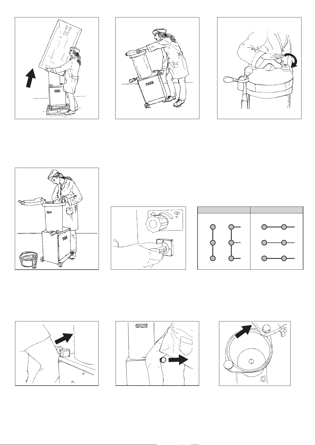
Unpacking.
Déballage.
Auspacken.
Uitpakking.
Udpakning.
Disimballo.
Desembalaje.
Proper displacement of machine.
Déplacement correct.
Richtiger Transport.
Correcte veplaatsing.
Korrekt flytning.
Spostamento corretto.
Desplazamiento correcto.
U
pper lid screws (E models).
crous couvercle (modèles E).
E
Deckelschrauben (E-modellen).
Deksel-schroeven (E-modellen).
Lågets møtrikker skrues af (modeller E).
Svitare dadi coperchio ( modelli E).
T
uercas tapa (modelos E).
400/380 Volt. 230/220 Volt.
Clean before use.
Nettoyer avant utilisation.
Vor Gebrauch reinigen.
Wassen voor gebruik.
Maskinen bør renses før den tages i brug.
Pulizia prima dell'utilizzo.
Limpiar antes de utilizar.
Start-stop
nterrupteur marche-arrêt (modèles i).
I
switch (i models only).
Schalter (i-Modellen).
Schakelaar (i-modellen).
A
fbryderkontakten (modeller i).
Interruttore (modelli i).
I
nterruptor (sólo modelos i).
V2
U2
W2
W1
V1
U1
L3
L2
L1
V2
U2
W2
W1
V1
U1
L3
L2
L1
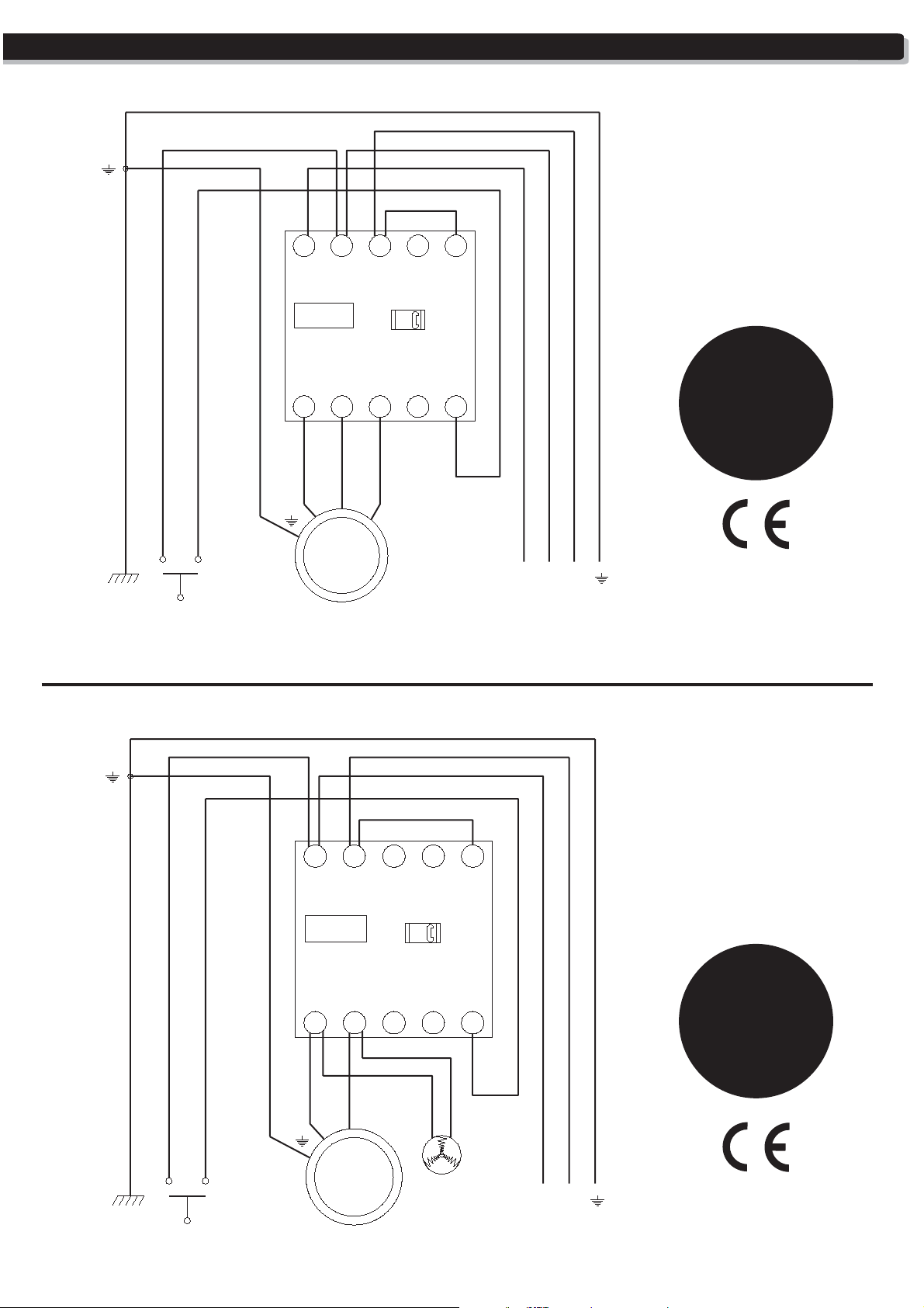
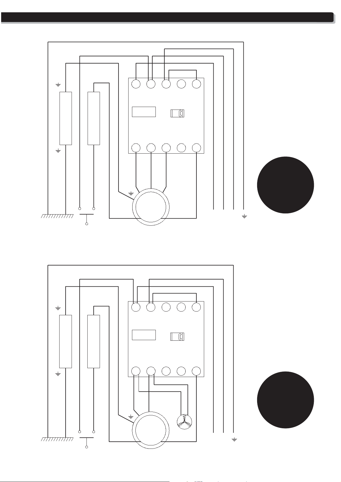
3-phase motor voltage change.
Changement voltage moteur triphasé.
Spannungswechsel 3-phasig motoren.
Veranderen van voltage 3-fasig motor.
OCmstilling af spænding.
ambio voltaggio motori 3 fase.
Posición plaquitas cambio voltaje motores trifásicos.
Raise piston.
Monter piston.
Kolben herauffahren.
Zuiger naar boven laten gaan.
Løfte stemplet.
Elevare pistone.
8
Subir pistón.
Lower piston.
Baisser piston.
Kolben herunterfahren.
Zuiger naar beneden laten gaan.
Sænke stemplet.
Abbassare pistone.
Bajar pistón.
Make room for mixture.
Laisser place pour mélange.
Raum für Füllgut.
Plaats laten voor de mengsel.
Ifyldning af farsen
.
Mettere l'impasto.
Dar cabida masa.

on lid
Insert green gasket.
Placer joint couvercle.
Deckeldichtung einlegen.
Grüne
Groene
dekseldichtingsring plaatsen.
vert
Placering af pakningen.
Mettere guarnizione verde.
Colocación
junta verde de tapa.
Installing locking nozzle/horn nut.
Placer écrou porte-embout.
Füllrohrverschlußmutter andrehen.
Wartel aandraaien.
Skru oml
øberen på.
Mettere dado porta-imbuto.
Colocar tuerca porta embudo.
Putting on nozzle/
horn.
Placer embout.
Füllrohr anbringen.
Worsthoorn plaatsen.
Pølsehornet sættes på.
Mettere imbuto.
Instalar
embudo.
Unscrew piston locking bolt.
Desserrer vis fixation piston.
Kolbenschraube lösen.
Zuigerschroef losdraaien.
Stempelbolten løsnes.
Allentare chiusura pistone.
Desenroscar
P
iston seals cleaning.
cierre pistón.
Nettoyage joints piston.
Kolbendichtungen reinigen.
Zuigerdichtingsringen schoonmaken.
Stempelpakningerne enses.
r
Pulire guarnizioni pistone.
Limpieza juntas pistón.
Remove piston.
Enlever piston.
Kolben herausziehen.
Zuiger uithalen.
Udtræk stemplet.
Allentare chiusura pistone.
Extraer pistón.
P
iston cleaning.
Nettoyage piston.
Kolben reinigen.
Zuiger schoonmaken.
Rens stemplet.
Pulire pistone.
Limpieza pistón.
9
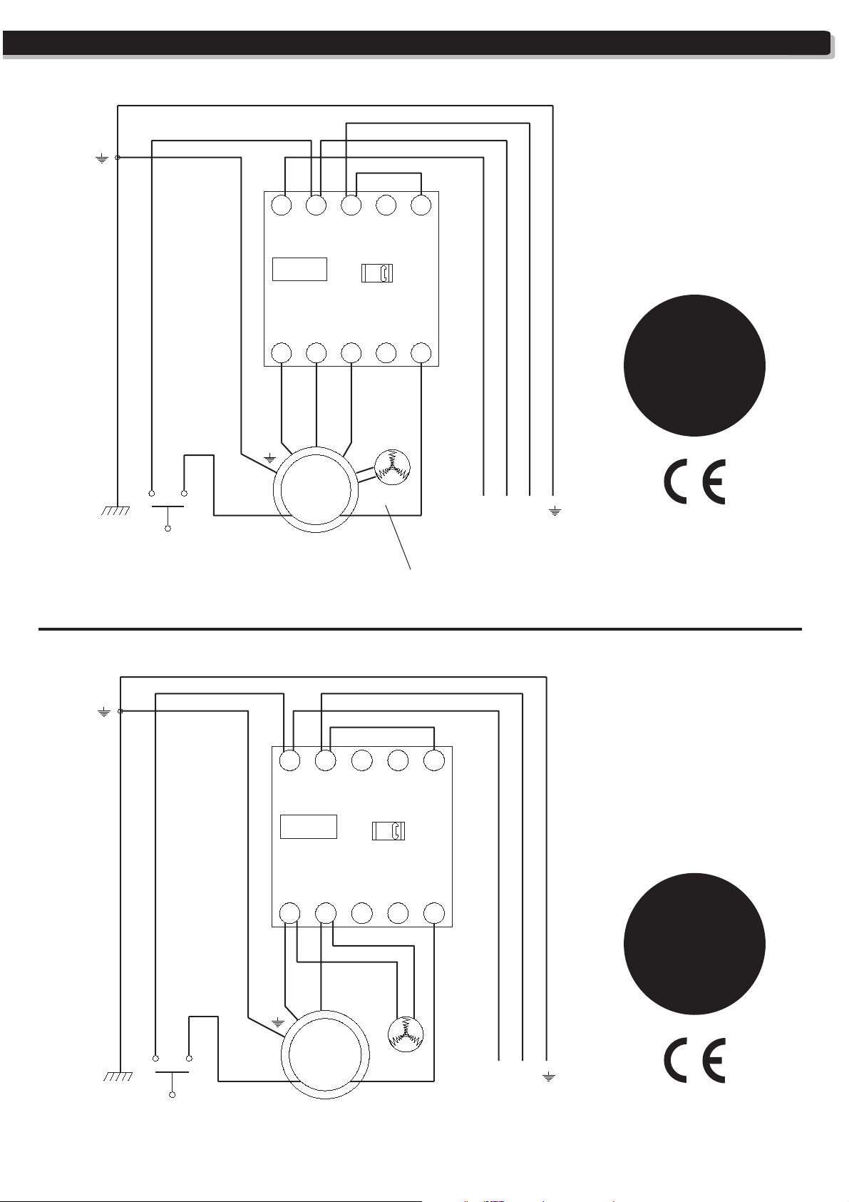
ELECTRIC SCHEMAS • SCHÉMAS ÉLECTRIQUES • ELEKTROSCHEMA • EL-SKEMAER • SCHEMI ELETTRICI • ESQUEMAS ELÉCTRICOS
H31.a
H42.a
Micro
31 L1
LC1K
4T12
T2 T36
V1U1
M
3~
Motor with internal
thermo protection
13L3 NO5L2 A1
14 A2
W1
Fan
NO
Fan on H42/H52 only
L1
L2
H52.a
automatic
3-phase
3-ph
400V
230V
L3
Micro
31 L1
LC1K
4T12
T2 T36
V1U1
M
1~
Motor with internal
thermo protection
13L3 NO5L2 A1
NO
14 A2
Fan
L1
H31.am
H42.am
H52.am
automatic
1-phase
1-ph
230V
220V
N
10
ELECTRIC SCHEMAS • SCHÉMAS ÉLECTRIQUES • ELEKTROSCHEMA • EL-SKEMAER • SCHEMI ELETTRICI • ESQUEMAS ELÉCTRICOS
H15.a
H20.a
H26.a
31 L1
13L3 NO5L2 A1
automatic
3-phase
LC1K
3-ph
4T12
T2 T36
NO
14 A2
400V
230V
V1U1
W1
Micro
3~
LC1K
M
31 L1
4T12
T2 T36
13L3 NO5L2 A1
NO
14 A2
L1
L2
L3
H15.am
H20.am
H26.am
automatic
1-phase
1-ph
230V
Micro
M
1~
220V
V1U1
Fan
L1
N
11
USA/CANADA ELECTRIC SCHEMAS • SCHÉMAS ÉLECTRIQUES USA/CANADA • ESQUEMAS ELÉCTRICOS USA/CANADA
USA/Canada only:
H26pa-UL/CSA
Terminal block
Micro
Terminal block
31 L1
LC1K
4T12
T2 T36
V1 W1U1
M
3~
Motor with internal
thermo protection
13L3 NO5L2 A1
NO
14 A2
L1
H15pa/H20pa
H31pa/H42pa
H52pa
automatic
3-phase
60Hz
3-ph
208V
220V
L3L2
12
Terminal block
Micro
Terminal block
31 L1
LC1K
4
2
T1
6
T2 T3
V1U1
M
1~
Motor with internal
thermo protection
13L3 NO5L2 A1
NO
14 A2
Fan
L1
USA/Canada only:
H15pam/H20pam
H26pam/H31pam
H42pam/H52pam
automatic
1-phase
60Hz
1-ph
•
220V
N
ELECTRIC SCHEMAS • SCHÉMAS ÉLECTRIQUES • ELEKTROSCHEMA • EL-SKEMAER • SCHEMI ELETTRICI • ESQUEMAS ELÉCTRICOS
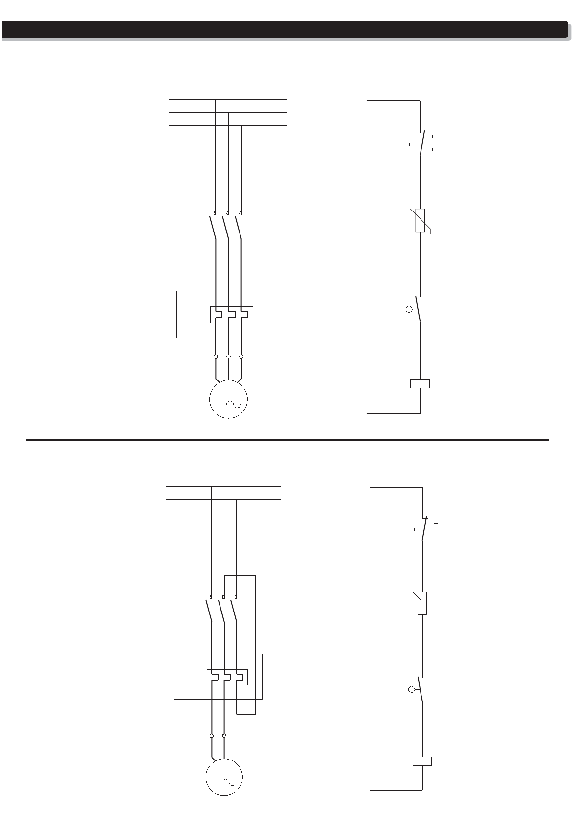
• ELECTRIC SCHEMA model A-automatic, 3-phase. • SCHEMA ELECTRIQUE Modèle A-automatique, triphas’e.
• ELEKTRISCHE SCHEMA Modelle A-automatisch, 3-phasig. • ESQUEMA ELÉCTRICO modelo A-automático, trifásica.
1/L1
3/L2
5/L3
-KM2
-F1
1
2
1
2
U1
L1
95
-F1
96
5
3
-S1
-KM1
-R1
T
13
14
A1
A2
H15/H20/H26:
OPTIONAL THERMAL RELAY.
RELAIS THERMIQUE OPTIONNEL.
THERMORELAIS AUF WUNSCH.
RELE TERMICO OPCIONAL.
6
4
5
3
6
4
H15/H20/H26:
OPTIONAL THERMAL RELAY.
RELAIS THERMIQUE OPTIONNEL.
THERMORELAIS AUF WUNSCH.
V1
W1
RELE TERMICO OPCIONAL.
M
3
L2
• ELECTRIC SCHEMA model A-automatic, 1-phase. • SCHEMA ELECTRIQUE Modèle A-automatique, monophasé.
• ELEKTRISCHE SCHEMA Modelle A-automatisch, 1-phasig. • ESQUEMA ELÉCTRICO modelo A-automático, monofásica.
1/L1
5/N
-KM2
-F1
1
2
1
2
U1
5
3
6
4
5
3
6
4
H15/H20/H26:
OPTIONAL THERMAL RELAY.
RELAIS THERMIQUE OPTIONNEL.
THERMORELAIS AUF WUNSCH.
RELE TERMICO OPCIONAL.
V1
M
1
L1
H15/H20/H26:
OPTIONAL THERMAL RELAY.
RELAIS THERMIQUE OPTIONNEL.
THERMORELAIS AUF WUNSCH.
RELE TERMICO OPCIONAL.
N
-F1
-S1
-KM1
-R1
95
96
T
13
14
A1
A2
13

NOTICE: This cap is for transport purposes only!. Before operating the
machine, replace it with the enclosed depressurized oil cap/dipstick.
ATTENTION: avant l’installation de la machine, veuillez rémplacer ce bouchon
d`étancheité transport par le bouchon-tige niveau huile dépressurisé livré.
ACHTUNG: Dieser Verschluß ist nur für Transportzwecke: Entfernen Sie ihn
unbedingt vor den Inbetriebnahme der Maschine und ersetzen Sie ihn durch den
beigefügten Öleinfüllverschluß mit Druckausgleich und Ölmeßstab.
LET OP: Deze dop is alleen voor transportdoeleinden! Verwijder deze vóór het in
gebruik nemen van de machine en vervang deze door de bijgevoegde
sluitdop/oliemeetstaaf met ontluchtingsgat.
ATENCION: este tapón sólo es válido para las tareas de transporte!. Antes de
conectar la máquina, reemplácelo por el tapón-varilla despresurizador entregado.
NO
OK
]
ALWAYS LEAVE
YOU HAVE FINISHED USING THE MACHINE.
LAISSEZ TOUJOURS
VOUS AVEZ FINI D'UTILISER LA MACHINE.
WENN DIE ARBEIT
ZYLINDER IMMER GANZ NACH UNTEN GEFAHREN WERDEN.
WANNEER U KLAAR
DE CILINDER STAAN.
SITÚE SIEMPRE
ACABE DE UTILIZAR LA MÁQUINA.
To remove the meat barrel do not use the hydraulic system; do it by removing the piston
with the supplied wrench.
N'utilisez pas le groupe hydraulique pour démonter le cylindre à viande; faite le en
démontant le piston à l'aide de la clé d’extraction fournie.
Gebrauchen Sie nicht das Hydrauliksystem, um den Fleischzylinder zu zerlegen; machen
Sie dies indem Sie den Kolben anhand der beigefügten Ausziehvorrichtung
herausnehmen.
Gebruik nooit het hydraulische systeem om de vlees-cylinder te demonteren; doe dit
met het uitnemen van de zuiger met behulp van de bijgevoegde sleutel.
Para desmontar el depósito carne no utilice el grupo hidráulico; hágalo desmontando el
pistón con la llave suministrada.
THE PISTON IN THE BOTTOM OF THE MEAT CYLINDER ONCE
LE PISTON AU FOND DU CYLINDRE À VIANDE QUAND
MIT DER MASCHINE BEENDET IST, SOLLTE DER KOLBEN IM
BENT MET HET WERK, LAAT U DAN DE ZUIGER ONDERIN
EL PISTÓN EN EL FONDO DEL DEPÓSITO DE MASA CUANDO
14
PRES.
T - 2467
WARNING • ATTENTION • ACHTUNG • LET OP
ADVASRSEL•FIGYELEM•ATTENZIONE•ATENCIÓN
400/230 V dual-voltage machine factory preset to:
Machine bi-tension 400/230 V, branchée à l'usine à :
400/230 V Maschine wurde in unserer Fabrik auf folgende Spannung eingestellt:
400/230 V machine is standaard aangesloten op:
400/230 V maskine er fra fabrikken koblet til:
A gép kettös müködésü 400/230 V, gyártóüzemi beállítás:
Macchina a doppio voltaggio 400/230 V, collegata alla fabbrica a:
Máquina bi-tensión 400/230 V, conectada en fábrica a:
3x400 V • 50 Hz
Machine must be properly grounded and/or connected to a circuit leakage breaker.

ENGLISH
TABLE OF CONTENTS -- INSTRUCTION MANUAL FOR FILLERS/STUFFERS:
ILLUSTRATIONS:
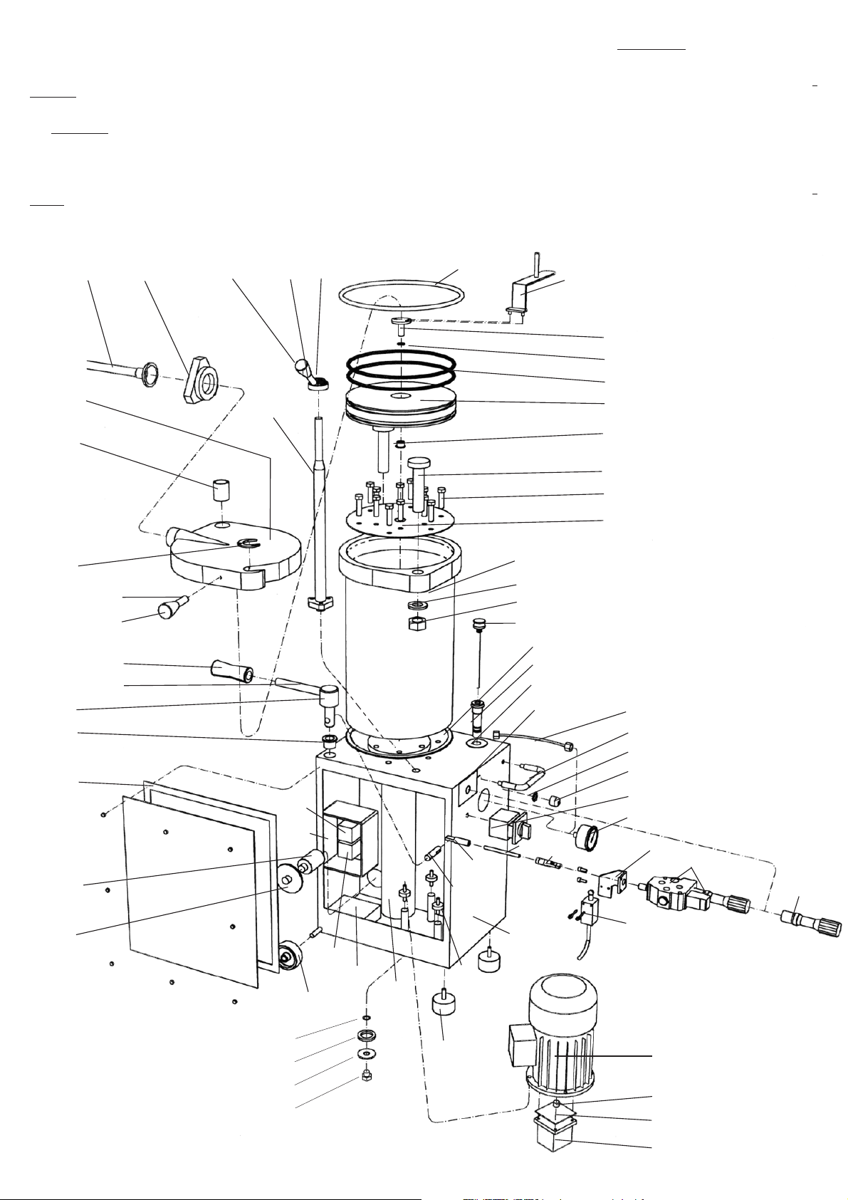
LABELED DIAGRAM
SPARE PARTS LIST
ESSENTIAL ELEMENTS
DRAWINGS
ELECTRIC DIAGRAMS FOR "A" MODELS (AUTOMATIC WITH CONTACTOR)
1 SAFETY INSTRUCTIONS
2 LIST OF POSSIBLE OPERATING HAZARDS
2.1 MECHANICAL HAZARDS
2.2 ELECTRICAL HAZARDS
2.3 NOISE HAZARDS
2.4 PERSONAL HEALTH HAZARDS
3 TECHNICAL FEATURES
3.1 GENERAL INFORMATION
3.2 DENOMINATION
3.3 MODELS
3.4 TECHNICAL SPECIFICATIONS
4 DELIVERY
5 INSTALLATION
5.1 UNPACKING AND POSITIONING
5.2 CONNECTING THE MACHINE
5.3 HYDRAULIC OIL FILLING
5.4 CHANGING THE VOLTAGE
5.4.1 CHANGING THE VOLTAGE ON “A” MODELS (AUTOMATIC-CONTACTOR)
5.4.2 CHANGING THE VOLTAGE ON “I” MODELS (SWITCH)
6 OPERATING INSTRUCTIONS
6.1 HANDLING STEPS
6.2 USEFUL TIPS
7 CLEANING
7.1 CLEANING INSTRUCTIONS
7.2 CLEANING PRECAUTIONS
7.3 CLEANING CHECKLIST
8 MAINTENANCE
8.1 MAINTENANCE AND INSPECTION SCHEDULES
8.2 MAINTENANCE AND INSPECTION TIPS
9 TROUBLESHOOTING GUIDE
1. SAFETY INSTRUCTIONS
This machine has moving mechanical parts and uses voltages that are potentially ha zardous. Severe, even life-threatening, personal
injury could result if the instructions contained in this manual are not followed. Before operating the unit, please read this manual
thoroughly. This manual should be kept for future reference an d given to every user of the mac hine. The following clauses limit the
liability of the manufacturer and its representatives :
• T HIS MACHINE SHOULD ONLY BE INSTALLED BY A QUALIFIED ELECTRICIAN. ONCE INSTALLED, DO NOT TAMPER WITH
THE ELECTRICAL WIRING OR COMPONENTS OF THE MACHINE.
• DO NOT USE THE MACHINE WITHOUT HAVING RECEIVED PREVIOUS INSTRUCTIONS ABOUT ITS USE, MAINTENANCE
AND SAFETY DEVICES FROM AN EXPERIENCED OPERATOR.
• READ THE INSTRUCTION MANUAL CAREFULLY BEFORE USING THE MACHINE.
• DO NOT USE THE MACHINE WITHOUT THE PERSONAL SAFETY EQUIPMENT REQUIRED BY LAW.
• DO NOT TAMPER WITH THE FIXED GUARDS, THE SAFETY INTERLOCK ELECTRICAL SWITCHES OR ANY OTHER SAFETY
DEVICES.
• ALWAYS KEEP HANDS AT A SAFE DISTANCE FROM THE MOVING PARTS OF THE MACHINE.
• DO NOT LEAVE MACHINE UNATTENDED WHILE SWITCHED ON OR IN OPERATION.
• ALWAYS DISCONNECT THE POWER SUPPLY BEFORE REMOVING SHROUDS, REMOVABLE GUARDS, COVERS, DOORS,
FENCES, PANELS, ETC. FOR SERVICING, CLEANING, OR REPAIRS.
15

• DO NOT OPEN THE MACHINE OR TAMPER WITH ITS INTERNAL PARTS. THERE ARE NO INTERNAL COMPONENTS THAT
REQUIRE ADJUSTMENT OR MAINTENANCE ON THE PART OF THE USER.
• SHOULD THE MACHINE MALFUNCTION, TURN IT OFF IMMEDIATELY AND NOTIFY THE SUPERVISOR.
• Installation must be in accordance with the operating instructions and with local and state hygiene standards and safety codes.
Compliance with codes is the responsibility of the Owner and Installer.
• Before operating the machine, make sure that it is properly grounded and/or connected to a circuit l eakage breaker and thermal
switch. Failure to do so could result in electric shock.
• Make sure the safety signs and stickers are firmly affixed to the machine, that they are legible, and that they have not been blurred or
erased after the machine is cleaned. If they become damaged or lost, ask your dealer for new ones and replace them.
• Keep your work area well lit and free of obstacles.
• When operating the machine never wear loose clothi ng or jewelry that could get caught in the moving parts.
• Unplug the machine when not in use.
• Keep children and on-lookers at a safe distance.
• Do not pull on the cord to remove the electrical plug from the socket.
• To avoid damaging the electrical cord, keep it out of areas where it can be stepped on.
• Do not alter or modify the machine’s original design in any way.
• Should the machine need repairs, consult the official dealer where the machine was purchased.
• Use only genuine TALSA parts and accessories and have them properly installed by a qualified technician.
• This machine has been designed exclusively for meat processing. Any other use of this machine is not in accordance with its
intended application. The manufacturer assumes no responsibilit y for any possible damage or injury resulting from im proper use of
this machine.
Additional operating instruction manuals are available from your dealer.
Your local dealer will be happy to answer any further questions you may have.
2. LIST OF POSSIBLE OPERATING HAZARDS
Read and review thoroughly the following operating hazards.
2.1 MECHANICAL HAZARDS
• Crushing hands, fingers etc. on the barrel when closing the lid.
• Crushing hands, fingers etc. between the lid and the pist on while the latter is being raised, especially when the lid is not c ompletely
open.
• Crushing hands, fingers etc. between the piston and the u pper part of the base during the dismantling of the removable barrel on E
models.
• Personal injury should the machine tip over if it is raised too high while being moved (since the fillers are on wheels, this is an
important hazard).
• Foot injuries should the piston fall during dismantling or cleaning.
2.2 ELECTRICAL HAZARDS
• Electric shock due to direct or indirect contact with electrical current.
• Electric shock due to defective electrical parts.
2.3 NOISE HAZARDS
Hearing damage should any modification of the machine’s or iginal design raise noise emission levels above 85 dB(A).
2.4 PERSONAL HEALTH HAZARDS
Changes in the nature of the food mixture if hygiene and cleaning instructions have not been followed.
3. TECHNICAL FEATURES
3.1 GENERAL INFORMATION
The H hydraulic piston fillers/stuffers combine technology, superior materials, and high engineering standards along with practical
applications to provide quick and simple operation, as well as ease of maintenance.
• Totally enclosed hydr aulic oil reservoir. Equipped with two plastic anti-vibr ation legs, as well as t wo non-castor wheels and a handle
to make moving the machine easier.
• TALSA Fillers are noted for having a totally rectified barrel (P models with fixed barrel) and allo wing for simple dismantling and
cleaning (E models with removable barrel).
• Start and stop of the motor either manually by s witch (i models) or automatically via contactor (A models). In the latter, the machine
uses electricity only when the knee lever is pressed. T his results in savings on electricity and less wear and tear on the machine’s
components. It also allows for quieter operation, since the motor-pump is not in constant use.
• Release of the knee lever causes pisto n decompression and instantly stops the product flow, regardle ss of nozzle size or product
density.
• The specially reinforced pressure system allo ws for easy processing of even the densest and coldest sausage m ixtures; machine
equipped with pressure gauge (P models).
• Speed control knob situated near the operator for quick and precise adjustment.
16

• Operation via ergonomically positioned kne e lever allows the operator to keep both hands free. The piston is lowered b y reversing
the knee lever control.
• Automatic lid lock with adjustable pressure closing (P models) precludes the need for flywheels.
• T he piston, which can b e removed eas ily, has t wo gaskets to pr event the mixtur e from escaping bet ween the joints (exce pt H42/H52
models). The machines have been designed to allow for quick access to all components, thus enabling easy cleaning and
maintenance.
• Appropriate for all kinds of natural or artificial casings.
• Made to CE and USDA standards.
• Waterproof internal electric box (models A).
ACCESSORIES included: Three nozzles ø12, 20, 30 mm. Spanner and piston extraction screw. Spare lid gasket. Horn holding nut. Oil.
Instruction manual.
OPTIONS: H26 stainless steel lid, piston and nut (H26S model). Single phase. Portio ning device PH5 00. Curved nozzle valve. Speci al
diameter or length nozzles (table 6.2 below).
3.2 DENOMINATION
• Filler/Stuffer H15/20/26/31/42 with fixed barrel P. • Filler/Stuffer H15/26 with removable barrel E.
3.3 MODELS
H15Pi H15PA H15Ei H15EA
H20Pi H20PA
H26Pi H26PA H26Ei H26EA
H31PiS H31PAS
USDA UL
H26S
H31S
H42S
H26PA
H26PAS
H42PiS H42PAS H52S
H52PiS H52PAS
• P = fixed barrel. • E = removable barrel. • A = start and stop of the motor automatically via contactor.
• i = start and stop of the motor by switch. • S = stainless steel lid, piston and nut
3.4 TECHNICAL SPECIFICATIONS
H15 H20 H26 H31 H42 H52
Mixture barrel capacity in liters 14.9 19.9 25.6 30.8 41.5 51,6
Mixture barrel capacity in kg of meat (approx) ±12 ±16 ±22 ±28 ±36 ±44
Barrel capacity in pounds of meat (approximate) ±26 ±35 ±48 ±62 ±79 ±96
Hydraulic oil tank capacity (liters) 10 10 15 15 25 25
Hydraulic oil tank capacity (US gallons) 2.6 2.6 4 4 6.6 6.6
Mach measurements (width x depth x height), cm 42x67x100 42x67x120 46x72x112 47x73x112 55x78x120 59x80x120
Mach measurements (width x depth x height), in. 17"x26"x39" 17"x26"x47" 18"x28"x44" 18"x29"x44" 22"x31"x47" 23"x32"x47"
Cardboard packaging measurements, cm 55x60x116 55 x60x139 55x60x139 55x60x139 -- -Cardboard packaging measurements, inches 22”x24”x46” 22”x24”x55” 22”x24”x55” 22”x24”x55” -- -Cardboard packaging volume, m³/cbm 0.38 0.46 0.46 0.46 -- -Wooden crate packaging measurements, cm -- -- -- -- 67x72x147 67x72x147
Wooden crate packaging measurements, inches -- -- -- -- 26"x28"x58" 26”x28”x58”
Wooden crate packaging volume, m³/cbm -- -- -- -- 0.70 0.70
Net/gross weight of 3-phase machine with oil, kg ±100 / ±115 ±117 / ±135 ±135 / ±155 ±180 / ±200 ±260 / ±290 ±330 / ±360
Net/gross weight 3-phase of mach with oil, pounds ±220 / ±253 ±258 / ±298 ±298 / ±342 ±397 / ±441 ±573 / ±683 ±777 / ±848
3-phase motor noise level dB(A) LEQ at 1 m ±58 ±58 ±61 ±61 ±64 ±64
1-phase motor noise level dB(A) LEQ at 1 m ±61 ±61 ±64 ±64 ±67 ±67
Max./min. environmental relative humidity, % 20 to 90%
Recommended hydraulic oil viscosity 5º Engler 50ºC (equiv. ISO3498: cat HL VG46, DIN8659: HL-46)
Max./min. environmental temperature ºC / ºF +5 to +40ºC (+40 to +110ºF)
Stainless steel grade AISI304 (equiv. DIN 1.4301, AFNOR Z6CN 18.09)
Aluminum grade AFNOR AG6T-Y (equiv. ASTM G8A - UNE L2331)
Three-phase motor data 50/60 Hz
Motor power HP 0.75 1.25 2 2.5
Motor power kW 0.55 0.94 1.5 1.87
Motor consumption Amp 380/400 Volt 1.9 2.5 3.7 4.5
Motor consumption Amp 220/230 Volt 3.3 4.3 6.4 7.8
Single-phase motor data 50/60 Hz
Motor power HP 1.25 1.75 2.25 2.5
Motor power kW 0.94 1.31 1.68 1.87
Motor consumption Amp 220/230 Volt 6.9 9 10.5 12.5
Capacitor µF 25 µF / 450 V. 40 µF / 450 V. 55 µF / 450 V. 55 µF / 450 V.
17

4. DELIVERY
The machine is delivered on a pallet and comes protected by cardboard packagi ng (H42/H52 models co me in a wooden crate, optiona l
for all other models). Besides the machine, this packaging includes an instruction manual, a p ack of 3 nozzles (12, 20 and 30mm in
diameter), a spanner, a piston extraction screw, and a spare lid gasket. We use only recyclable packaging (please recycle). The
transport company assumes sole responsibility for damage received in transit, check condition upon receipt.
5. INSTALLATION
(Estimated time: 45 minutes. Machine should only be installed by a qualified technician and in compliance with local codes).
The electrical installation of the workplace should be equipped with power surge full protection, which should then be adjusted to the
technical specifications of your particular unit (see number 3 below).
5.1 UNPACKING AND POSITIONING
Always keep the machine in a vertical position. Take the machine out of its box. Remove the knee lever (and the u pper lid scre ws for E
models) from the inside of the barrel and set them in their proper positions.
Do not use the knee lever to move the machine. T he machine comes with two fixed (non-castor) wheels in the front and two plastic
anti-vibration legs in the back; lift the back part of the machine using the transport handle and mov e the machine to the desir ed location
(two people are necessary for moving the heavier H42 and H5 2 models). Do not raise the filler/stuffer too high when moving it since it
could tip over, causing personal injury. Pl ace the m achine on a lev el surface. Sho uld the machi ne wobble, adjust the a nti-vibration legs
until it is perfectly stable and level. The machine should be placed so that the plug is easily accessible.
IMPORTANT: Remove the protective transport cap on the oil inlet ( marked OIL) and replace it with the depressuri zed oil cap/dipstick
enclosed with the machine. Also make sure that the air hole s located at the base of the b arrel are totally clear; if not, the piston will no t
function properly.
5.2 CONNECTING THE MACHINE
Make sure the electrical characteristics of the machine (connection, voltage, an d frequency) are suited to your power source. (These
specifications are given in detail on the technical sp ecifications sticker affixed to the machine itself; there is a tolerance of ±10% for
voltage and of ±2% for frequency). If the specifications are compatible with your power source, refer to the 6.OPERATING
INSTRUCTIONS section below.
If the electrical features of the machine are not compatible with your power source an d your machine is a dual voltage, three-phase
unit, adjust the voltage as described below in the 5.4.CHANGING VOLTAGE section.
Once the machine has been installed and the oil level i nside the reservoir has been c hecked using the dipstick attached to the oil inlet
screw, check the turning direction of the three-phase motor. If the phases are correctl y adjusted, the piston will rise and fall when the
knee pedal is pushed. If the phases are incorrect, the pump will not work properly; the motor will make noise, but the piston will not
move. Stop immediately and interchange two of the three phases in the plug. Make sure that the plug and outlet are appropriate for the
machine.
IMPORTANT, the wiring in the electrical cord is normally assigne d as follows: Phase(s): • Black, Brown, Gray • Ground wire: Twocolored Yellow/Green or Green. Check the wiring before connecting; call a qualified electrician if the electrical specifications do not
correspond with your power source.
5.3 HYDRAULIC OIL FILLING
The H filler/stuffer is delivered with hydraulic oil already in the internal reservoir; therefore, the initial addition of oil to the hydraulic
system is usually unnecessary.
In the exceptional case that a machine is delivered without hydraulic oil in the reservoir, do not turn it on. Fill the reservoir as follows:
• Remove the oil reservoir screw (marked OIL) located in the upper part of the base.
• Check that the correct level of oil is inside the reservoir by using the dipstick (with max./min. marks) attached to the oil reservoir cap.
• Using a funnel, po ur the hydraulic oil into the tank. Do not fill the reservoir t o the top since a certain amount of air m ust
reservoir to allow for expansion. Use oils for medium pressure hydraulic assemblages (approx. 100 bar), and of a viscosity of
approximately 5º Engler (equivalent to IS03498: cat HL VG46 or DIN8 659: HL-46). After filling the reservoir, raise and lower the
piston several times to purge any remaining air from the hydraulic circuit.
Always fill the reservoir to the maximum level without exceeding it since the more oil there is in the reservoir, the mor e effectively the
heat given off by the hydraulic assemblage will be cooled. This helps lengthen the life of the oil.
Because there should be no loss of oil or oil vapors, an adequate level of hydraulic oil should last several years (between 2500 and
5000 hours of use), making it unnecessary t o check the oil level as long as the machine is functi oning well. For more information, see
the 8.MAINTENANCE section below.
5.4 CHANGING THE VOLTAGE
IMPORTANT: Only for three-phase machines with dual voltage motor 3 80/220 Volt (400/230 Volt for EU), etc. This operation should
only be carried out by a qualified electrician.
Do not connect the machine to the power source. If already plugged in, unplug it and leave it disconnect ed for the entire process.
Remove the screws from the steel lid on the base. Remove the lid.
5.4.1 CHANGING THE VOLTAGE ON A MODELS (AUTOMATIC-CONTACTOR)
MOTOR: Open the connection terminal box of the motor by unscre wing the four screws. Loosen the six small nuts on the connection
terminals and place the plates in the correct position.
CONTACTOR: will need to be replaced by a qualified technician to a n ew one of same voltage than power supply.
remain in the
5.4.2 CHANGING THE VOLTAGE ON “I” MODELS (SWITCH)
MOTOR: Open the connection terminal box of the motor by unscre wing the four screws. Loosen the six small nuts on the connection
terminals and place the plates in the correct position.
18

6. OPERATING INSTRUCTIONS
IMPORTANT: Before operating the unit, read this manual thoroughly. Test the machine when it is empty before using it on food.
6.1 HANDLING STEPS
• Loosen the screws on the upper lid (only for E models) and open the lid with a slight upward motion to reduce friction.
• Wash the meat barrel, the underside of the lid, and the appropriate nozzle with hot water.
• Lower the pressure of the machine to the minimum by turning the red knob that regulates the filling speed counter-clockwise.
• Plug the machine in.
• Turn the gray switch located on the right of the machine to the “I” (start) position (I models only).
• Turn the machine on by pushing the knee lever.
• Push the knee lever all the way back to lower the piston enough to make room for the desired amount of mixture.
• Place the m ixture in th e meat barrel, pres sin g each ne w load of mixture down to avo id the formation of air pockets which could break
the casing during the filling process.
• Put the green lid gasket in place.
• Using the knee pedal, raise the piston until the mixture reaches the top of the barrel.
• Using food fat or another USDA approved shortening, grease the upper part of the lid gasket and the underside of the lid.
• Carefully clos e the lid with a light lifting m ovement to avoid friction, takin g care not to pinch or crimp the cover gask et in the process.
To close the lid, use only the lever incorpor ated in the lid itself; do not use the nozzle. Take extrem e care not to trap or pinch your
hands while closing the lid.
• After putting the screws back on the upper lid (E models onl y), place the optimum-size nozzle (largest diameter and shortest length
possible) on the lid, locking it in place by turning the triangular nozzle nut. Prepare the proper amount of casing.
• Push the knee lever all the way for ward to the piston raising position. Always push the knee lever firmly; do not use it as a speed
control regulator.
• Carefully raise the pressure by slowly turnin g the pressure control k nob clockwise. Do not raise the pr essure suddenly, as this could
cause the mixture to come out of the nozzle too quickly.
• Note how the piston will begin to rise and air will come out of the nozzle.
• Once the mi xtu re begins to come out of the n ozzle, releas e t he pressur e and pl ace the casing on the n ozzle. Adj ust the red pre ssure
control knob to select the optimum speed.
• Once the casing has been filled, push the knee l ever back to the piston lowering position until th e piston is at its lowest level in the
barrel.
• To stop the hydraulic assemblage, bring the knee pedal to the central position.
• Turn the gray switch located on the right of the machine to the “O” (stop) position (I models only).
• When finished using the machine, clean it, lo wer the piston to its lowest position in the barrel, unplug the machine and make sure
that the machine cannot roll.
6.2 USEFUL TIPS
• Do not use the machine without having received previous instructions from an exper ienced operator.
• This instruction manual should be read carefully and fully understood before using the machine.
• Test the machine when it is empty before using it on food.
Observe all the appropriate hygiene measures when handling food products; use adequate protective equipment and procedures
(washing, gloves, cap, apron, etc.).
To produce sausage with a better appearance and less smearing, as well as for more uniform mi xture and less wear and tear on t he
machine, we recommend the use of:
• Horn with the largest diameter and shortest length possible.
• Finely chopped mixtures at the least coldest temperature possible.
Consequently we recommend avoiding very long nozzl es or nozzles with small diameters when using roughly chopped or very cold
mixtures.
If nozzles of special dimensions are needed, order them from your dealer. There is a wide range of sizes available:
Model: B C D E F G H I
External diameter, mm Ø 12 15 18 20 25 30 38 43
Internal diameter, mm Ø 10 12 15 17 22 27 35 40
Tube length, mm 160 195 195 195 195 195 220 235
Total nozzle length, mm 210 245 245 233 220 220 245 260
Never use the nozzle to close the lid since the rim could break. Close the lid with the lid lever only.
Do not open or close the lid without the green gasket in place since this could lead to scratches on the lid and clamp.
The barrel lid cannot be opened without first slightl y lowering the piston by placing the knee ped al in the down position. This will stop
the mixture from blocking the opening.
Place the machine as close to the work surface as possible. The locations of the nozzl e and knee lever allow the nozz le to be located
completely over the work surface, thus guaranteeing that no liquid falls onto the floor or the operator.
In order to prevent overheating in i models, turn the machine off after use. Turn the motor on only when in use.
19

Work at a reasonable pace, thus avoiding c onstant stopping and restarting of the hydraulic assemblage. This machine is not designed
to withstand permanent, uninterrupted use at high pressure, but rather to run intermittently with pauses to allo w for the dissipation of
the heat generated, the amount of which depends on the consistency of the mixture. Because of the pressure transmitted by the pump,
after prolonged periods of use the hydraulic oil may reach temper atures of up to 60ºC (140ºF) and the base side panel ma y become
warm to the touch.
7. CLEANING
IMPORTANT: In order to avoid mechanical hazards durin g cleaning oper ations and p iston dismantlin g, always open the l id completely
when raising the piston.
7.1 CLEANING INSTRUCTIONS
To clean the outside of the machine use hot water and a mild cleanser.
Do not use any abrasive products, especially those that could scratch warning stickers and labels.
Never wet or dampen the electrical elements of the machine (switches, cables, etc.). Never use a jet of water to clean any part of the
machine, especially the air holes on the side of the oil tank cap.
At the end of each workday, the underside of the lid (the mixture exit hole), as well as the nozzle(s) and the nozzle nut should be
cleaned thoroughly. If necessary, clean the inside of the nozzles with a round brush. Do not op en or close the lid without the green
gasket in place since this could scratch the lid and clamp.
Using hot water only, rinse the lid bolt and bearing to eliminate any resid ue that could crystallize (salts, spices, etc.) and thus impede
the proper functioning of the lid.
The upper part of the black piston gasket should also be cleaned daily, following these steps:
• Open the lid completely and remove the green lid gasket.
• Press the knee lever until the piston rises to its uppermost position. P art of the black piston gasket will now be accessible via the
upper part of the barrel. Clean it with a damp cloth.
We recommend that you periodically clean the piston and barrel interior thoro ughly:
• Loosen the screws on the upper lid (E models only), open the lid completely and remove the green lid gasket.
• Press the knee lever until the piston rises to its uppermost position.
• With the piston at its highest position, simultaneousl y push the knee lever and, with the aid of the two pivots of the wrench supplied,
unscrew the piston-locking bolt (two turns) located in the center of the piston.
• Screw the wrench completely into the piston hole. The piston will rise above the rim of the barrel.
• Pull the wrench up to remove the piston from the barrel.
• Unplug the machine.
• Clean the inside of the cylinder. Make sure that the bottom of the cylind er is comp letely DRY to av oi d the formatio n of water droplets,
which could eventually lead to the formation of rust on the upper part of the base.
IMPORTANT: Piston and barrel cleaning can also be done by dismantling the removable barrel (E models only); however, to avoid
mechanical hazards as well as damage to the piston gaskets, we advise removal of the piston only.
7.2 CLEANING PRECAUTIONS
Because of the weight of the piston, use caution when moving it.
Clean the piston and the black piston gaskets (1 or 2, dependi ng on the model). To avoid damaging the gaskets, never use sharp or
pointed tools (knives, screwdrivers) to remove them. To reduce the noise caused by the movement of the piston, grease the piston
gaskets with food fat or another USDA approved shortening before putting them back into the barrel.
Never introduce water inside the barrel since it c ould filter down to the base of the machine and affect the electrical and mechanical
components. The holes in the bottom of the barrel are vents for air only.
To reassemble the piston, make sure that the bottom of the barrel is completely dry, then place the piston in the barrel an d screw the
piston-locking bolt tight, making sure that the smaller gasket is prop erly placed. Raise and lower the piston, and tighten the piston
locking bolt again, making sure it does not bend against the pressure of the lid. Grease the thread of the piston-locking bolt before
replacing it; this will make future dismantling easier.
When the machine is not in use, leave the piston hea d at the bottom of cylinder, where it will be subm erged in hydraulic oil. T
lengthen the life of the ram and the gaskets.
For correct hygienic control, see the 7.2.CLEANING CHECKLIST section below.
7.3 CLEANING CHECKLIST
IMPORTANT: Never use a jet of water to clean any part of this machine!. When using detergents, disinfectants or maintena nce oils,
follow the manufacturers’ special instructions.
We recommend the use of cleaning or disinfecting products mentioned herewith. To clean the machine manually, always use
appropriate safety equipment (latex gloves, plastic aprons, etc.). Always rinse the machine thoroughly after using any kind of detergent
of disinfectant. Always follow the instruction provided by the manufacturer of the product.
Product Manuf Name Notes
Neutral detergent pH7 Henkel TOPAX 10
Due to its neutral pH, no special precautions are necessary. Rinse
thoroughly.
Detergent for manual cleaning Henkel RIK Use appropriate precautions and protective gear. Rinse thoroughly.
Alkaline detergent with disinfectant
incorporated
Henkel TOPAX 68 Use appropriate precautions and protective gear. Rinse thoroughly
Disinfectant with ammonium salts Henkel TOPAX 91 Use appropriate precautions and protective gear. Rinse thoroughly.
his will
20

GENERAL CLEANING ADVICE:
Cleaning steps Products Method Tools Notes
Superficial cleaning Manual Spatula
Extensive cleaning Mild detergent Manual Brush, bucket Leave product to work ± 15 minutes.
Rinsing Warm water Manual Sponge, bucket Warm water 40/50 º C - 100/120 º F.
Inspection Check critical points and problematic parts.
Disinfecting Disinfectant products Manual Sponge, cleaning cloth After completing all other cleaning operations.
Rinsing Drinking water Manual Sponge, bucket
Drying Cleaning cloth
Maintenance Lubricating oil Manual Cleaning cloth External machine parts.
SPECIFIC CLEANING ADVICE:
Interval Cleaning area Method Products Tools Notes
Underside of the lid, lid gasket,
Daily
Fortnightly
These cleaning instructions have been elaborated for companies with just one shift; shorter intervals should be observed in companies
with many work groups.
IMPORTANT: Among the parts which should be cleaned daily (see “SPECIFIC CLEAN ADVICE” above), the piston bolt retaining
screw must be cleaned thoroughly by dismantling it. In E models, the following parts should als o be dismantled for better cleaning: lid
closing nuts, lid, barrel.
Piston removal: See section 7.1 above.
inside of the barrel and piston
bolt retaining screw
Piston, piston gaskets and gasket
of piston bolt retaining screw
Manual
Manual
Mild detergent,
warm water
Mild detergent,
warm water
Remove all residue directly after use, removing
smaller machine parts if necessary.
Sponge,
cleaning cloth
Sponge,
cleaning cloth
Eliminate dirt from retaining screw
using a brush if necessary. Avoid
build up of residues.
To remove the piston, follow the
instructions above.
8. MAINTENANCE
IMPORTANT: Unplug the machine before proceeding with maintenance and inspection.
During maintenance and inspection operations always follow the safety instructions in this manual.
Mechanical breakdowns caused by inadequate or improper maintena nce can lead to high repair costs as well as work stoppages;
therefore, regular and adequate maintenance is indispensable.
The safety and life of the machine depend on many factors, including proper maintenance.
Because different companies have different shift schedules, it is impossible to prescribe in advance h ow often you should proce ed with
inspections, maintenance or replacement. Adjust your inspection routine to the number of work groups you have in your company.
Our local dealer will be delighted to give you further information.
The table below contains information about mainte nance and inspection (control intervals, critical points, etc.) for a machine under
normal use.
8.1 MAINTENANCE AND INSPECTION SCHEDULES
After reading the following, consult the MAINTENANCE AND INSPECTION TIPS section for more details.
Control interval Critical points / Maintenance information
• Check green lid gasket and replace it if necessary.
Daily
Monthly
Yearly
Every 2500-5000 service hours
8.2 MAINTENANCE AND INSPECTION TIPS
Green lid gasket
spare gasket comes with the machine. The gasket is made from a non-toxic material that is safe for alimentary use. Place the glued
joint of the gasket under the lid bolt. To reduce lid friction and e xtend lid g asket life, befor e closing al ways greas e the gre en gasket and
the lower part of the lid with animal fat or another USDA approved.
Black piston gasket
gasket with animal fat or another USDA approved shortening before placing it in the barrel.
Hydraulic oil level
level marked without exceeding it since the more oil ther e is in the reservoir, the more effectively the heat given off b y the hydraulic
assemblage will be cooled. This helps lengthen the life of the oil.
: Replace if damaged or if leaks are observed. This gasket is reversible, i. e. it can be us ed with either side facing up. A
: Replace if damaged or if leaks are observed. To reduce noise caused b y the movement of the piston, grease th is
: The oil level can be tested with the dipstick provided on the oil inlet screw. Always fill the reservoir to the maximum
• Check the two black piston gaskets and replace them if necessary.
• Check the air holes located at the base of the barrel and clear them of any obstruction.
• Check the lid closure and tighten if necessary by regulating the lid fixing bolts (P models only).
• Check hydraulic oil level and refill the reservoir if necessary.
• Change hydraulic oil.
• Check oil filter and replace it if necessary.
21

Hydraulic oil duration: The life of hydraulic oil varies depending on m any factors, e.g. temperature and pressure at which the machine is
run, the presence of humidity or residual water, etc. Normally it can la st between 2.500 and 5.000 hours of service. If the oil loses
viscosity, becomes impure, or turns a whitish color from having had water pumped into it, drain the oil by empt ying the housing via the
plug located at the bottom of the machine. Refill the oil following the instructions found i n the INSTALLATION section above. Because
there is no natural loss of oil or oil v apors, an adequate l evel of hydraulic oil should last several years, making it unnecessar y to c heck
the oil level regularly. If the oil level is insufficient, the piston will not move smoothly, since air will be entering the circuit.
Changing the hydraulic oil
: Remove the oil outlet plug located at the bottom of the bas e an d drain the r es ervoir, em pt yin g the oi l i nto an
appropriate recipient (please recycle used oil). Replac e the plu g an d sea l the oil outl et site hermetic ally. Using a funnel, fill the reservoir
with 10 liters (for H15/H20 models), 15 liters (for H26/H31 models) or 25 liters (for H42/H52 models) of hydraulic oil via the tank
opening. Do not fill the reservoir to the top since a certain amount of air must be present to allow for expansion. Use oils for medium
pressure hydraulic assemblages (approx. 100 bar), and of a viscosit y of approximately 5º Engler (equiv alent to IS03498: cat HL VG46
or DIN8659: HL-46). After filling the reservoir, raise and lower the piston several times to eliminate air pockets from the hydraulic circuit.
Oil filter
: Located inside the oil reservoir, the oil filter is not accessible to the user and should only be repl aced by a qua lified tec hnician.
To remove the oil filter remove the two screws that attach the closing clamp to the filter and pull the filter outward. Normally, th e filter
should not become dirty or present any abnormalit y. If the filter must be changed, use a similar filter with a thread of 3/8” BSP and a
filtering capacity of 10 liters per minute, (5 liters per minute for H15/H20). After reassembling the unit, the closin g clamp must be seal ed
hermetically.
Oil temperature
: Because of the pressure transmitted by the pump, after prolonged periods of use the hydraulic oil may reach
temperatures of up to 60ºC (140ºF) and the base side panel may become warm to the touch. This machine is not designed to withstand
permanent, uninterrupted use at high pressure, but rather to run intermittently with pauses to allow for the dissipation of the heat
generated, the amount of which depends on the consistency of the mixture.
Cylinder ram
: In order to lengthen the life of the hydraulic cylinder ram, leave the piston head at the bottom of the c ylinder when the
machine is not in use. The ram will thus be completely submerged in hydraulic oil.
Lid closure
: The lid of the barrel can be shut more or less tightly depend ing on how watertight the closure should be. If the mixture is
customarily dry, the closure can be loosened, making it easier to close the lid. If, however, the mixture contains more liquid, the closure
should be tighter to avoid leaks. To loosen t he lid in E models, loosen the upper lid screws until the desired seal is obtained. For P
models, loosen the nuts located beneath the clamp and ei ther loosen or tighten the 2 lid fixing bolts. Then retighten the 2 lock nut s
completely. To keep crystallized residue (from salts, spices, etc.) from impeding the proper closure of the lid, remember to rins e the lid
bolt and bearing with hot water after using the machine.
Lack of power
: If the machine seems to lack power, notify the service department of the dealer where the machine was purchased.
They should verify the following points: that the air holes located at the base of the barrel are complet ely free of obstruction, that the
piston and the piston gaskets are perfectly clean and free of residue which could inhibit the movement of the piston, that the voltage of
the power source is compatible with that selected for the motor, that the motor is not functioning with only two phases, that t here is
enough hydraulic oil, that there is no oil leakage from the hydraulic screws or pipes, and that the oil filter is clean and u nobstructed.
Electrical cord: If the electrical cord becomes damaged, have it replaced immediately with a cord of identical tec hnical characteristics
(your local distributor can supply you with one).
Spare parts
: To order spare parts, contact the dealer where the machine was purchased. Be sure to gi ve full details when identifying
the machine (model, serial number, year of manufacture, power, voltage, frequency, etc.). This data can be found on the technical
specifications plate located on the machine itself.
9. TROUBLESHOOTING GUIDE
Problems Possible causes Solutions
Machine does not work.
Electric motor runs, but the
piston does not move up or
down.
Piston moves up and down but
machine seems to lack power.
Machine is unplugged. Plug the machine in.
Machine connected to a lower voltage. Change machine voltage.
No voltage in one or more phases. Check fuses, plugs, and switches.
Switch located on the right of the machine is in
0-stop position (I models only).
Turn the switch to 1-start position.
0-1 switch (I models only) is defective. Call an electrician.
Internal on/off microswitch in knee lever is
defective or not properly adjusted (A models
only).
Call an electrician to replace or adjust the
microswitch.
Speed regulator on minimum. Turn speed regulator knob clockwise.
Motor is turning in the wrong direction. Interchange two of the three phases in the plug.
The air holes located at the base of the barrel
are obstructed.
Clean air holes.
Piston and piston gaskets are dirty. Clean piston and piston gaskets.
Voltage of power source is not compatible with
voltage selected for the motor.
Three-phase motor (if available) is only
functioning with two phases.
Call an electrician to change motor voltage.
Adjust phases at the power source.
Lack of hydraulic oil. Fill the oil reservoir to the “MAX.” mark.
Oil leakage from hydraulic screws or pipes. Call your local dealer.
Oil filter is dirty. Call your local dealer to replace it.
22

FRANÇAIS
TABLE DES MATIÈRES MODE D’EMPLOI POUSSOIRS :
ILLUSTRATIONS :
DESSIN GÉNÉRAL
LISTE DES PIÈCES DÉTACHÉES
ÉLÉMENTS ESSENTIELS
DESSINS
SCHÉMAS ÉLECTRIQUES MODÈLES "A" (AUTOMATIQUES PAR CONTACTEUR)
1 MESURES DE SÉCURITÉ
2 LISTE DE RISQUES
2.1 RISQUES MÉCANIQUES
2.2 RISQUES ÉLECTRIQUES
2.3 RISQUES ACOUSTIQUES
2.4 RISQUES POUR LA SANTÉ
3 FICHE TECHNIQUE
3.1 INFORMATION PRÉALABLE
3.2 DÉNOMINATION
3.3 TYPES
3.4 SPÉCIFICATIONS TECHNIQUES
4 LIVRAISON
5 INSTALLATION
5.1 DÉBALLAGE ET MISE EN PLACE
5.2 BRANCHEMENT
5.3 REMPLISSAGE D'HUILE HYDRAULIQUE
5.4 CHANGEMENT DE TENSION
5.4.1 CHANGEMENT DE TENSION SUR MODÈLE A (AUTOMATIQUE-CONTACTEUR)
5.4.2 CHANGEMENT DE TENSION SUR MODÈLE I (INTERRUPTEUR)
6 UTILISATION
6.1 ÉTAPES A SUIVRE
6.2 CONSEILS UTILES
7 NETTOYAGE
7.1 INSTRUCTIONS DE NETTOYAGE
7.2 PRÉCAUTIONS DURANT LE NETTOYAGE
7.3 PROGRAMME DE NETTOYAGE
8 ENTRETIEN
8.1 TABLEAU D'ENTRETIEN ET D'INSPECTION
8.2 CONSEILS D'ENTRETIEN ET D'INSPECTION
9 DIAGNOSTIQUES ET SOLUTIONS DE PROBLÈMES
1. MESURES DE SÉCURITÉ
Cette machine a des pièces mobiles et son voltage est potentiellement dangereux. Une mauvaise utilisation peut provoquer des
dommages physiques très graves, pouvant même arriver à mettre vo tre vie en danger. Avant de mettre l’appareil en marche, nous
vous conseillons de lire attentivement les instructions qui suivent et de conserver ce ma nuel pour votre référence et de le remettre à
tous les nouveaux usagers. Ces instructions limitent la responsabilité du constructeur et de ses représentants :
• NE FAITES PAS L’INSTALLATION ELECTRIQUE VOUS-MÊME; FAITES LA RÉALISER DE PRÉFÉRENCE PAR UN
ÉLECTRICIEN PROFESSIONNEL DÛMENT QUALIFIÉ, EN RESPECTANT LES NORMES NATIONALES DE SÉCURITÉ.
• N’UTILISEZ PAS LA MACHINE SANS AVOIR AUPARAVANT REÇU DES INSTRUCTIONS PRÉCISES DES MESURES DE
SECURITÉ, D’UTILISATION ET DE NETTOYAGE DE LA PART D’UN EXPERT.
• LISEZ ATTENTIVEMENT LE MODE D’EMPLOI AVANT TOUTE UTILISATION DE LA MACHINE.
• N’UTILISEZ PAS LA MACHINE SANS PORTER LES VÊTEMENTS ET SANS AVOIR LES ACCESSOIRES DE PROTECTION
NÉCESSAIRES STIPULES PAR LA LOI.
• NE JAMAIS MODIFIER NI MANIPULER LES DISPOSITI FS DE SÉCURITÉ (MÉCANIQUES OU ÉLECTRIQUES) INSTALLÉS SUR
LA MACHINE.
• MAINTENEZ LES MAINS ÉLOIGNÉES DES COMPOSANTS EN MARCHE.
• N’ABANDONNEZ PAS LA MACHINE PENDANT SON FONCTIONNEMENT OU QUAND ELLE EST BRANCHÉE.
23

• TOUJOURS DÉBRANCHER L’APPAREIL AVANT DE PROCÉDER À SON NETTOYAGE, À L’ENTRETIEN OU À SA
RÉPARATION.
• NE PAS TOUCHER A L’INTÉRIEUR DE LA MACHINE : EN PRINCIPE, AUCUNE PIÈCE N’A BESOIN DE RÉGLAGE.
• SI LA MACHINE NE FONCTIONNE PAS CORRECTEMENT, ARRÊTEZ-LA IMMÉDIATEMENT ET PRÉVENEZ LE SUPERVISEUR.
• L’installation de la machine doit être effectuée conformément au mode d’emploi ainsi qu’aux normes locales d’hygiène et de
Sécurité. Ne pas suivre ces normes compromet exclusivement la responsabilité du Client et de l'installateur.
• Avant la mise en marche vérifiez la connexion de toutes les phases avec la correspondante prise de terre et/ou interrupteurs
différentiels et magnétothermiques. Une négligence à ce niveau peut provoquer une décharge électrique.
• Les plaques et adhésifs de sécurité doivent être placés à un endroit parfaitement visible sur la machin e. Assurez-vous qu’ils ne
s’effacent avec le nettoyage. Au besoin de les remplacer, sollicitez-les à votre fournisseur.
• Maintenez toujours la zone de travail bien éclairée et facile d’accès.
• Assurez-vous à ce que tout ce qui est susceptible d’être entraîné par les pièces en mouvement (vêtements, colliers,...) soit hors
d’atteinte de la machine.
• Ne laissez pas la machine branchée si vous ne l’utilisez pas.
• Maintenez les enfants et les personnes non-autorisées à une distance de sécurité suffisante.
• Pour débrancher, ne tirez pas sur le cordon mais sur la fiche.
• Veillez à ce que le câble d’alimentation é lectrique de la machine ne soit pas dans une zone de passage où il peut être piéti né et
s’abîmer, ce serait dangereux.
• Ne modifiez dans aucun cas la conception originale de la machine.
• Confiez toute réparation au Distributeur qui vous a vendu la machine.
• Employez toujours des pièces de maintenance d’origine TALSA et faites les installer p ar un professionnel.
• Cette machine est conçue pour la transformation de viandes. Tout autre usage de ce lle-ci de la machine est au risque exclusif du
Client. Le fabriquant n'est pas responsable des dégâts causés par une mauvaise manipulation.
Cette notice d’utilisation doive être gardée pour future consultation et livré à chaque nouveau utilisateur de la machine.
En cas de besoin de manuels supplémentaires, demandez-les à votre Distributeur.
Pour toute information supplémentaire, veuillez vous diriger à votre Distributeur.
2. LISTE DE RISQUES
Lisez et évaluez correctement les risques identifiés ci-dessous :
2.1 RISQUES MÉCANIQUES
• Se prendre la main, les doigts, etc., entre le cylindre et le couvercle, en refermant le couvercle.
• Se prendre la main, les doigts, etc., entre le couvercle et le piston, si vous faites monter le piston, le couvercle n’étant pas
complètement ouvert.
• Se prendre la main, les doigts, etc., entre le piston et la partie supérieure de la base, en faisant descendre le piston durant le
démontage du cylindre pour les modèles E.
• Si vous levez la machine plus qu'il ne le faut ell e risque de tomber sur vous (étant donné que les poussoirs ont des roulettes, ce
risque est très important).
• S’écraser le pied si le piston tombe au sol pendant son démontage ou nettoyage.
2.2 RISQUES ÉLECTRIQUES
• Décharge électrique causée par un contact direct ou indirect avec l’électricité.
• Décharge électrique causée par des pièces électriques défectueuses.
2.3 RISQUES ACOUSTIQUES
Assourdissement causé par une modification de la conce ption origina le de la machine, provoqua nt une émission de bruit supéri eure à
85 dB(A).
2.4 RISQUES POUR LA SANTÉ
Altération de la composition naturelle de la viande causée par un manque d’hygiène et de nettoyage.
3. FICHE TECHNIQUE
3.1 INFORMATION PRÉALABLE
Les poussoirs hydrauliques série H réunissent une technologie, des matériaux excellents et une haute ingénieurie avec des
applications pratiques pour atteindre un maniement simple et rapide et un entretien facile.
• Réserv oir intérieur d’hui le indépe ndant. Équipé de 2 sup ports antivibratoire s en caoutchouc, 2 roulettes fixes et une poignée po ur un
déplacement aisé.
24
 Loading...