

Omcan Food Machinery 1000-STE Installation Manual
http://www.turbovac.nl, e-mail: info@turbovac.nl.
User manual
Art. no. 96.06.5.1505/05.03
Vacuum packaging machines
"STE-Series"
“SB-Series”
Manufactured by:
Het Sterrenbeeld 36, 5215 ML 's-Hertogenbosch, The Netherlands
P.O.Box 2261, 5202 CG 's-Hertogenbosch, The Netherlands
tel: +31(0)73-6271271, fax: +31(0)73-6271200
http://www.hfe.nl, e-mail: info@hfe.nl

2003 HFE Vacuum Systems BV
All rights reserved.
No part of this document may be reproduced and/or published by means of printing, photocopy, microfilm or any other method, without the
prior written permission of the manufacturer. This also applies for the accompanying illustrations and/or diagrams and schematics.
The information in this document is based on the general data associated with the construction, material qualities and working methods,
known at the moment of publication, so that we reserve the right to make changes without giving prior notice.
This document is applicable to the indicated models of the Turbovac packing machine in the version supplied. The manufacturer therefore
does accept any liability for any form of damage or injury resulting from deviating from the specifications of these machines as supplied to
you.
All possible care was taken when creating this document, but the manufacturer accepts no liability for mistakes or any consequences
thereof.
TAKE THE TIME TO READ THIS DOCUMENT THOROUGHLY TO ACQUAINT YOURSELF WITH THE
CORRECT AND APPROPRIATE USE OF THE TURBOVAC VACUUM PACKING MACHINES.
2003-05
2
96.06.5.1505-IM-en/05.03

Preface
CONTENTS
1. General......................................................................................... 5
2. Safety instructions and danger warnings................................. 7
3. The machine .............................................................................. 11
3.1 Operation .....................................................................................................11
3.1.1 Sensor control.................................................................................................... 11
3.1.2 Time control ....................................................................................................... 11
3.2 Options ........................................................................................................11
3.2.1 Less-vacuum...................................................................................................... 11
3.2.2 Vacuum plus (vac+) ........................................................................................... 12
3.2.3 Gas .................................................................................................................... 12
3.2.4 Sealing ............................................................................................................... 12
3.2.5 Soft-air ............................................................................................................... 12
3.2.6 Multi-cycle .......................................................................................................... 12
4. Installation ................................................................................. 13
4.1 Machines with a transparent cover ...........................................................13
4.2 Machines with a metal cover......................................................................14
4.3 Installation ...................................................................................................15
4.4 Connecting the gas.....................................................................................16
4.5 Connecting the seal-pressure....................................................................16
5. Control panel “STE-series”...................................................... 17
5.1 Control panel...............................................................................................17
5.1.1 Symbols ............................................................................................................. 18
5.1.2 Factory settings.................................................................................................. 18
5.2 Programming of the STE-series control ...................................................19
5.2.1 Programming with an open cover...................................................................... 19
5.2.2 Programming with a closed cover...................................................................... 20
5.2.3 Special functions................................................................................................ 21
6. Control panel “SB-series”........................................................ 23
6.1 Control panel...............................................................................................23
6.1.1 Symbols ............................................................................................................. 24
6.1.2 Factory settings.................................................................................................. 24
6.2 Programming of the SB-control.................................................................25
6.2.1 Programming with an open cover...................................................................... 25
7. Packing ...................................................................................... 26
7.1 Dry products................................................................................................26
7.2 Moist and fluid products ............................................................................28
96.06.5.1505-IM-en/05.03
3

Preface
8. Maintenance ...............................................................................29
8.1 Cleaning ...................................................................................................... 29
8.2 Cover rubber............................................................................................... 29
8.2.1 Machines with a transparent cover .................................................................... 29
8.2.2 Machines with a stainless cover ........................................................................ 30
8.3 Power cable ................................................................................................ 30
8.4 The vacuum pump...................................................................................... 30
8.4.1 Warming up the pump (STE-series) ..................................................................30
8.4.2 Filling with oil...................................................................................................... 31
8.4.3 Changing the oil ................................................................................................. 32
8.5 Oil dampers and springs ........................................................................... 32
8.6 Sealbeams and counter beams................................................................. 33
8.6.1 Replacing seal wire and teflon tape (single seal beam) .................................... 33
8.6.2 Replacing the seal wire(s) and the teflon tape (stainless seal beam) ............... 34
8.6.3 Replacing the seal wire(s) and the teflon tape (aluminium seal beam)............. 35
8.6.4 Fitting new wires on the seal beam: .................................................................. 35
8.6.5 Teflon lining to the seal beam............................................................................ 36
8.6.6 Replacing the counter beam silicon rubber .......................................................36
8.7 Vacuum hoses and pipes .......................................................................... 36
9. Faults and messages ................................................................37
10. Technical data............................................................................40
10.1 Machines in the stainless series............................................................... 40
10.1.1 Machines with a transparent cover (Table top and Mobile)............................... 40
10.1.2 Machines with a metal cover (Heavy duty) ........................................................ 41
10.2 Machines in the aluminium series ............................................................ 42
10.3 Connections ............................................................................................... 43
10.4 General data ............................................................................................... 43
11. CE-Declaration ...........................................................................44
4
96.06.5.1505-IM-en/05.03
Preface
1. GENERAL
Use of the manual
This manual is intended as a reference for users and technicians, who can install, use and maintain the
machine(s) stated on the front of this document in a safe way.
Pictograms and symbols at the machine
At the machine the following pictograms and symbols are attached to the machine:
WARNING
First consult the documentation with regard to:
Connecting the gas.
C
ONNECTING THE SEAL PRESSURE.
Danger of electrical shock.
• Before opening: First remove the plug from the wall socket!
• Only qualified personnel are allowed to open the unit.
Connection for extra sealing pressure
Connection for gas
Pictograms and symbols at the machine
In this manual the following pictograms and symbols are used (Fig. 4-2, Fig. 4-4, Fig. 4-6 of Fig. 4-7):
Note
Suggestions and advice to make carrying out the particular tasks or actions
easier.
Warning
Procedures that can result in damage to the machine, the surroundings and
the environment or physical injury when not carried out carefully.
DANGER
DANGER OF ELECTRICAL SHOCK!
Attention for the environment
Residual substances can contain valuable substances and materials that can be
suitable for recycling. Waste may also contain substances that are harmful to the
environment.
96.06.5.1505-IM-en/05.03
5
Preface
Illustrations
Because of the number of types and models it is impossible for practical reasons to illustrate every
variation. Nevertheless, the illustrations used show the principles of operation of the machine identified on
the front of this document.
Service and technical support
For information concerning specific settings, maintenance or repair work that is outside the scope of this
manual, contact the supplier of the machine. He is always ready to help you. Make sure that you have the
following data available:
• machine type
• serial number
This data can be found on the identification plate.
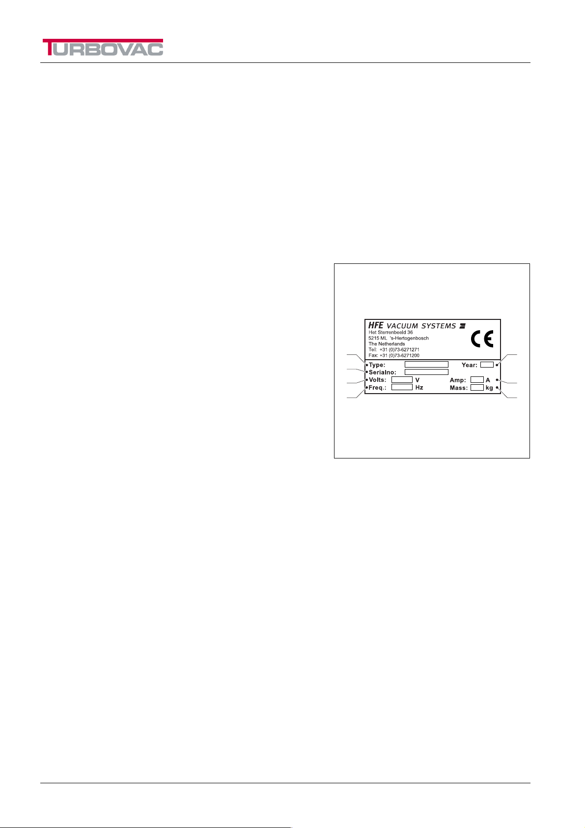
Identification of the machine
The identification plate (Fig. 1-1) contains the following
data:
A. Type
B. Serial number
C. Year of manufacture
D. Number of phases – voltage (Volt: V)
E. Frequency (Hertz: Hz)
A
B
D
E
C
F
G
F. Current (Ampere: A)
G. Weight (kilogram: kg)
Fig. 1-1: Identification plate
6
96.06.5.1505-IM-en/05.03

Safety instructions
2. SAFETY INSTRUCTIONS AND DANGER WARNINGS
General
The manufacturer accepts no liability whatsoever for damage or injury caused by not (strictly) following
the safety directions and instructions in this manual, or carelessness during the installation, use,
maintenance and repair of the machines identified on the front of this document and any accompanying
options.
The owner of the machine is responsible at all times for observing the locally applicable safety
regulations and guidelines.
Obey all safety instructions and guidelines as given in this manual.
Users manual
• Every user should be informed of the contents of this manual and follow the instructions in it carefully.
Management must train personnel on the basis of this manual and obey all directions and indications.
• Never change the order of the actions to be taken.
• Always keep the manual in the proximity of the machine.
Pictograms and instructions on the machine
• The pictograms, warnings and instructions that have been attached to the machine are part of the
safety measures taken.
• They should not be damaged or removed and they should remain present and readable throughout
the entire life span of the machine.
• Replace or repair unreadable or damaged pictograms, warnings and instructions immediately.
Intended use of the machine
1
The machine is designed for vacuum packaging food products, for 8 hours a day, 5 days a week. Any
other or extended use is not according to the purpose. The manufacturer accepts no liability for damage
or injury resulting from this. Use the machine only in a technically perfect condition, in accordance with
the purpose described above.
Technical specifications
The specifications stated in this manual may not be changed.
Modifications
Modification of (parts of) the machine is not permitted.
*1 The "Use in accordance with purpose” as established in EN 292-1 is the use for which the technical product is suitable
according to the statement by the manufacturer – including his directions in the sales brochure -. When in doubt it is the use that
appears to be the most usual from the construction, model and function of the product. Use in accordance with the purpose
means observing the instructions in the users manual.
96.06.5.1505-IM-en/05.03
7
Safety precautions
The machine is fitted as standard with the following
safety precautions:
• Main switch
• Cover switch
• Short circuit and overload safety
• Pump fan guards
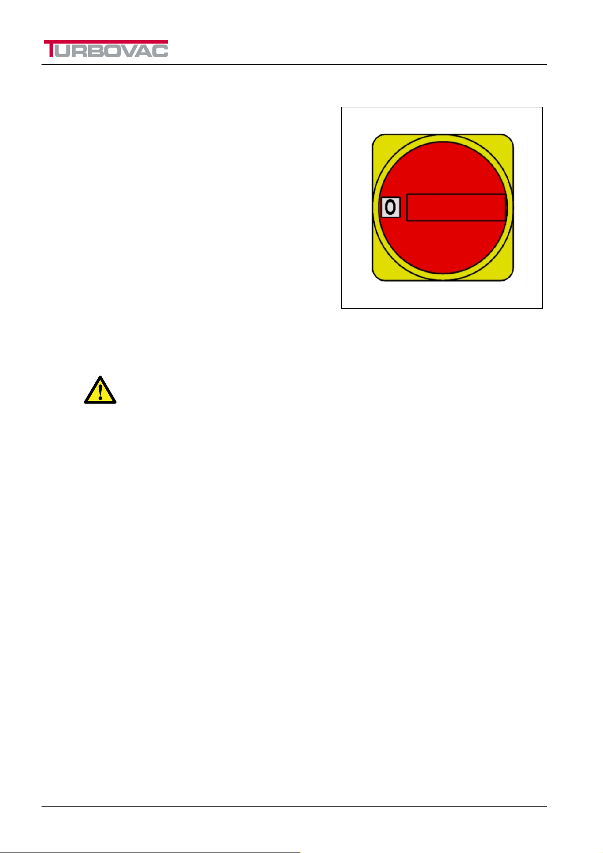
Main switch
With the main switch (Fig. 2-1) the machine can be
made voltage free. The main switch can also be used as
an emergency stop.
Cover switch
The Cover switch prevents the sealbeam(s) getting hot
as a result of a malfunction or defect when the Cover is
open.
Safety instructions
Fig. 2-1: Main switch
WARNING
T
HE SAFETY WORKS CORRECTLY WHEN THE MACHINE APPLIES A VACUUM, WHEN THE
COVER IS ALMOST CLOSED
REGULARLY AND
, WHEN NECESSARY, IT MUST BE REPAIRED IMMEDIATELY.
. THIS SAFETY MUST BE CHECKED FOR CORRECT OPERATION
Short circuit and overload safety
The machine is equipped with safety measures that prevent components becoming overheated by
overloading or short-circuiting.
Notes!
• The overload safety circuits on the seal transformers are self-resetting, which means that the safety
resets itself when the transformer has cooled down sufficiently. Operate the machine at a slower speed or
decrease the sealing time if the overload safety is trips regularly. Obviously, tripping the overload safety
shortens the lifetime of the transformer.
• On some machines extra sealing power (see chapter 1) can be installed. Consult your dealer.
• The short-circuit safety on the seal transformer is not self-resetting, which means that the transformer
must be replaced when this safety is tripped. Consult your dealer for this.
Pump fan guards
The vacuum pump is fitted with guards that prevent you touching the fan while it is running.
Safety measures
• All safety measures must be mounted correctly and may only be removed for maintenance and repair
work by suitably trained and authorised service technicians.
• The machine may never be used if the safety measures are not complete or not present, or when they are
or have been disabled.
• Safety measures may never be bridged.
8
96.06.5.1505-IM-en/05.03

Safety instructions
Use
• Inspect the machine before use and check it for damage.
• Switch the machine off at the main switch if it is not used for a long time.
• Never use sharp objects to operate the keys.
• Do not allow unauthorised persons into the working environment.
• Always ensure there is adequate ventilation, especially in confined places.
• Wear clothing that is suitable for the work. Loose clothing or jewellery can get between the Cover and the
vacuum chamber.
• Never use the machine in an environment in which there is an explosion risk.
• Replace the supply cable if it is damaged. Make sure that the supply cable cannot be damaged by
trapping this cable.
Hygiene
• Cleaning the machine is of the utmost importance when food products are wrapped. Clean the machine
regularly and thoroughly, preferably every day (§ 8.1).
• Work hygienically and prevent direct contact between the product and the machine as much as possible.
• Keep the operating controls free of dirt and grease.
• Lock the Cover if the machine will not be used for an extended period. This protects the vacuum chamber
from dust and dirt.
Service, maintenance and repairs
A clear distinction is made in this manual between the service, maintenance and repair work that can be
carried out by the user, and that which is reserved for trained and qualified service technicians only.
• Make sure there is adequate lighting.
• Always switch off the machine at the main switch during maintenance and/or repairs and/or remove the
plug from the socket.
• Observe the maintenance intervals specified. Overdue maintenance can lead to high costs for repair and
servicing and the right to guarantee can be lost.
• Always use parts, materials, lubricants and service techniques approved by the manufacturer.
• Never use worn tools and do not leave any tools inside the machine.
• Do not carry out service, maintenance or repair work to the machine, when it is indicated that the dealer
or qualified service technician should carry it out.
• Always have a recognised Turbovac dealer carry out repair and maintenance work.
• Safety measures that have been removed in order to carry out service, maintenance or repairs must be
refitted immediately after this work and they must be checked for correct operation.
96.06.5.1505-IM-en/05.03
9

Vacuum packing machines and the environment
Packaging
The packaging that is for the transportation and protection of the machine is mainly
made of cardboard and/or wood, which are suitable for recycling. Do not dispose of
the packaging as industrial waste but ask the sanitation department of your local
government authority where you can hand in the material.
Machine
When you dispose of your machine, it can still contain valuable substances and
materials. Do not dispose of the machine as industrial waste, but enquire at your
local government authority about the possibilities for recycling or environmentally
friendly disposal of the material.
• Most parts of the machine have been manufactured from stainless steel and can
be disposed of as scrap metal in the normal way. From health and
environmental considerations, no asbestos has been used.
• The printed circuit boards and the components mounted on them are electronic
waste. Deliver old printed circuit boards to specialised companies for
environmentally friendly processing.
Vacuum machines and the environment
Oil
Ask the sanitation department of your local government authority where you should
take the used oil for an environmentally friendly processing.
10
96.06.5.1505-IM-en/05.03

The machine
3. THE MACHINE
Products can be vacuum packed with the Turbovac vacuum packing machine.
The food products or products that are to be vacuum packed are put in a vacuum bag. This is placed in
the vacuum chamber of the machine. Then the cover is closed and the vacuum pump starts sucking the
air out of the chamber. When the required vacuum level has been reached, the opening of the bag
between the sealbeam and the counter beam is pushed together, after which the bag gets sealed. After
that the vacuum chamber ventilates and the cover opens automatically. The packed product can now be
taken out of the vacuum chamber.
3.1 Operation
The machine is equipped with a control system whose software prevents illogical settings being made.
The control has nine programs that can be changed as desired. Because of this it is possible to pack
various kinds of products perfectly in a simple way.
Note
The factory settings can always be recalled, which erases the programs that
have been entered by you (§ 5.1.2 en § 5.2).
3.1.1 Sensor control
The machine is equipped with a very accurate sensor control. With this sensor the pressure in the
vacuum chamber is measured during vacuuming and, when appropriate, during the gassing and slow
venting (soft-air option). The machine carries out the particular function automatically until the set
pressure has been reached. Because of this the result of that particular function is independent of the air
volume in the chamber or of the surrounding pressure, which guarantees a constant packing quality.
Notes
• The vacuum pressure is indicated in mbar.
The factory setting is from 5 mbar to 999 mbar.
• A changeable surrounding pressure has no effect on the measurement (for example when using in
an area on high mountains).
3.1.2 Time control
The sensor control can be switched off. The machine now operates via time control. This means that the
vacuum, gas and soft air functions operate until the set time has elapsed.
Notes
• To change from sensor control to time control, see § 5.2.3.
• The vac+, seal1 and seal 2 functions are always time controlled.
3.2 Options
The Turbovac machines can be equipped with the following options:
3.2.1 Less-vacuum
With this option the vacuum level can be set to over 200 mbar. The vacuum level for a machine without
the less-vacuum option is limited to 200 mbar.
The 330-STE, 430-STE, 450-STE and 490-STE are equipped with this option as standard.
96.06.5.1505-IM-en/05.03
11

3.2.2 Vacuum plus (vac+)
This option allows extra vacuuming, to give the air that is trapped inside the product time to escape from
the product. When the vac+ function is activated, the machine continues to vacuum for the set vac+ time
after reaching the set vacuum level.
This option can only be activated with a sensor control.
Note: The 330-STE, 430-STE, 450-STE and 490-STE machines are standard supplied with this option.
3.2.3 Gas
This option is used when delicate products must be packed. Applying certain mixtures of gas can
lengthen the storage life of the product.
A machine with the gas option is also equipped with the less-vacuum option.
3.2.4 Sealing
With the help of the following options optimal sealing of the vacuum bag can be achieved for every
situation
Different sealing seams
• Single seal
Standard seal wire
• Double seal
For extra seal security, two equal width sealing wires are mounted on the sealbeam. This sealing method
is the standard model.
• Cut-off seal
For simple removal of the bag surplus, a thin cutting wire is mounted next to the seal wire. The thin cutting
wire melts through the bag.
• Seal 1/2
The sealbeam is equipped with a sealing and a cutting wire, just like the cut-off beam. In this model the
time for sealing (the seal1 time) can be set independently of the cutting time (the seal2 time). This option
is used when the sealing and cutting times cannot be the same, such as with shrinking bags.
The machine
Extra seal pressure
With this option the seal pressure can be increased with compressed air (maximum 1 bar). The extra
pressure makes sure that the sealbeam is pushed harder against the counter beam during sealing.
This option should especially be fitted when the sealbeam is melting badly and a longer sealing time
gives insufficient improvement. This situation can occur especially when using the gas option.
The higher the gas pressure set, the more useful the extra seal pressure is.
Every machine but 530-STE AND 590-STE with gas setting over 500 mbar prefers extra seal pressure.
3.2.5 Soft-air
This option can be used when delicate products, or products with hard protrusions must be packed. The
vacuum chamber is then vented slowly so that the bag has the time to shape itself softly around the
product.
A machine with the soft-air option is also fitted with the less-vacuum option.
3.2.6 Multi-cycle
With this option the packing can be made even more fee of oxygen. The machine vacuums and gasses
more times in a row. The oxygen-free gas flushes out the residual air from the vacuum chamber so that
there is less oxygen left in the packing.
A machine with the multi-cycle option is also fitted with the gas option and the less-vacuum option.
12
96.06.5.1505-IM-en/05.03
Installation
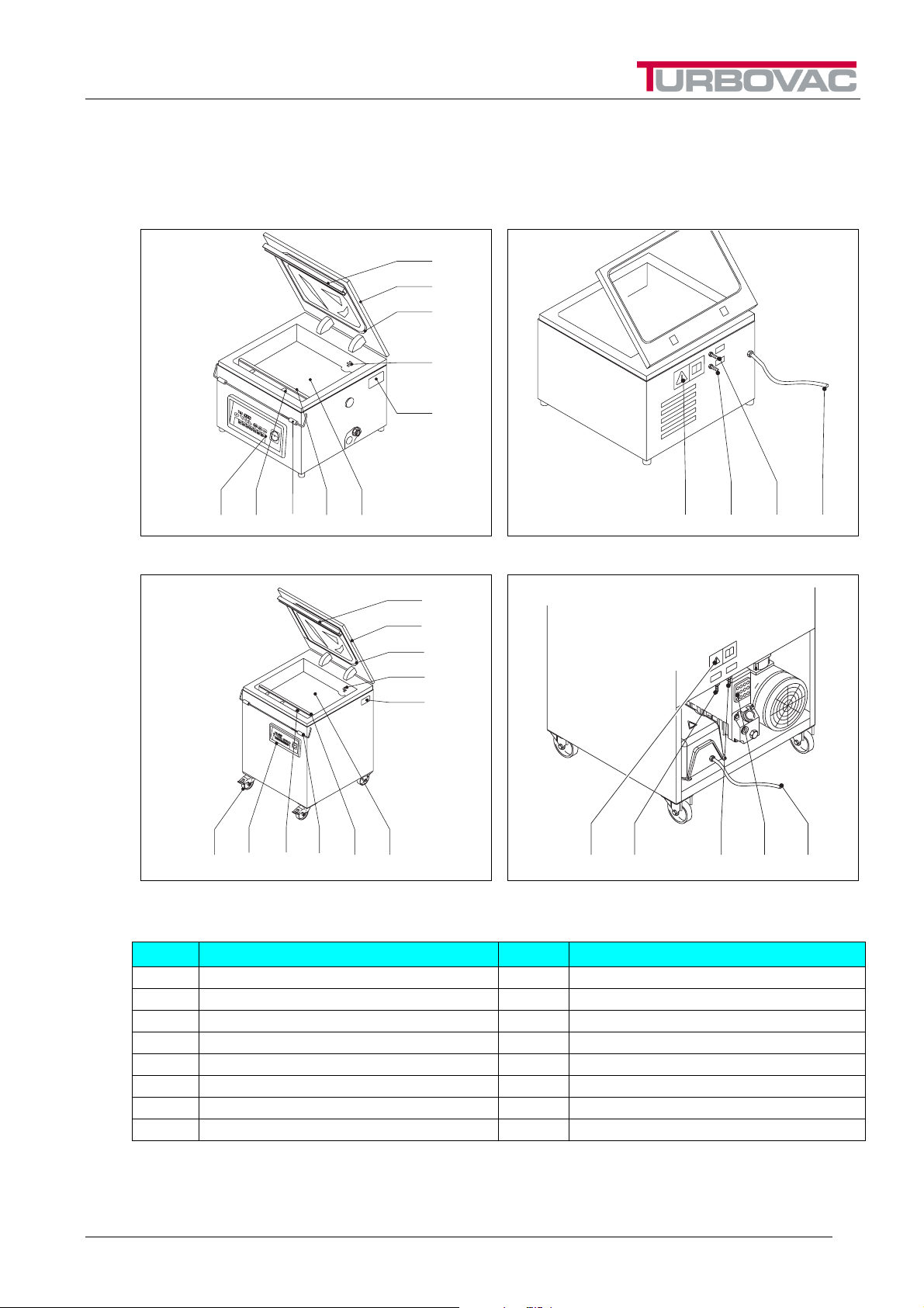
4. INSTALLATION
4.1 Machines with a transparent cover
K
J
I
H
G
ABCDE
Fig. 4-1: Table model
K
J
I
H
G
PABCDE
Fig. 4-3: Single chamber model (movable)
Pos. Description Pos. Description
A Control panel I Silicon gasket
B Gas pipes J Transparent cover
C Cover lock K Preassure beam
D Sealbeam L Stickers
E Filling plates M Gas connection
F Ventilation opening N Connection for extra seal pressure
G Identification plate O Power cable
H Suction opening P Wheel with brake
Fig. 4-2: Table model (connector side)
LM NFO
Fig. 4-4: Single chamber model (connector side)
LMNO
96.06.5.1505-IM-en/05.03
13
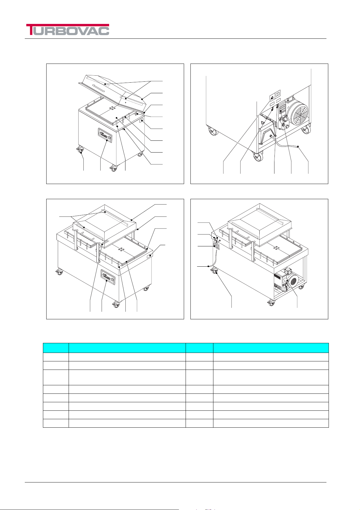
4.2 Machines with a metal cover
BAP
Installation
D
J
I
H
G
K
E
C
LM NFO
Fig. 4-5: Single chamber model (movable)
J
D
EHA B
Fig. 4-7: Double chamber model (with connectors)
Pos. Description Pos. Description
A Control panel I Silicon gasket
B Gas pipes J Metal cover
C
D Sealbeam L Stickers
E Filling plates M Gas connection
F Ventilation opening N Connection for extra seal pressure
G Identification plate O Power cable
H Suction opening P Wheel with brake
Cover lock
(not for double chamber machines)
I
K
G
Fig. 4-6: Single chamber model (connector side)
M
N
L
O
Fig. 4-8: Double chamber model
K Preassure beam
FP
14
96.06.5.1505-IM-en/05.03
 Loading...