

Page 1
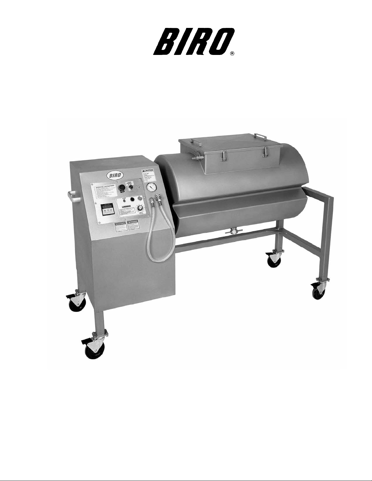
MODEL VTS-500
VACUUM TUMBLER
OPERATION MANUAL & PARTS LIST
The BIRO VTS-500 VACUUM TUMBLERS are versatile machines used for vacuum
tumbling all types of meats with marinaded blends of herbs and spices. All marinades should be FDA approved and meet F.S.I. standards. The BIRO VTS-500 produces equally impressive results with beef, pork, poultry and fish.
The unit is both easy to clean and maintain as well as sanitary in design and construction. The entire machine is built to give many years of trouble free service while
providing a unique line of marinated products for your customers.
ITEM No. VTS583-307
STARTING WITH SERIAL No. 544
ITEM No. VTS583-307
307-1-09-4
Page 2

TABLE OF CONTENTS
Page
NOTICETOOWNERSANDOPERATORS......................................... 1
SAFETYTIPS............................................................... 2
OPERATION................................................................ 3
CLEANING................................................................. 4
MAINTENANCE ............................................................. 5
PUMPFILTER.......................................................... 5-7
VACUUMPUMP......................................................... 8-9
GEARREDUCER ......................................................10-11
TOPROGRAMTIMER.....................................................12
TIMERPROGRAMNOTES..................................................13
PHOTOELECTRICEYE .................................................14-15
CONTROLPANEL–COMPONENTS.............................................16
CONTROLPANEL–REARVIEW ................................................17
DRUMASSEMBLY ...........................................................18
FRAMEASSEMBLYANDCOMPONENTS..........................................19
VACUUMHOSESANDFITTINGS.............................................20-21
COMPONENTCOVERANDREARDOOR .........................................22
OPERATORNOTES..........................................................23
WIRINGDIAGRAMS........................................................24-25
SPAREPARTSRECOMMENDATION .............................................26
OPERATOR’SSIGNATUREPAGE................................................27
LIMITEDWARRANTY.........................................................28
Page 3
BIRO’s products are designed to process food products safely and efficiently. Unless the operator is properly trained and supervised, however, there is the possibility of a serious injury. It is the
responsibility of the owner to assure that this machine is used properly and safely, strictly following
the instructions contained in this Manual and any requirements of local law.
No one should use or service this machine without proper training and supervision. All operators should read and be thoroughly familiar with the procedures contained in this Manual. Even so
BIRO cannot anticipate every circumstance or environment in which its products will be used.
You, the owner and operator, must remain alert to the hazards posed by the function of this equipment. No one under eighteen (18) years of age should operate this equipment. If you are uncertain about a particular task, ask your supervisor.
This Manual contains a number of safe practices in the SAFETY TIP section. Additional warnings are placed throughout the Manual. Warnings related to your personal safety are indicated by:
Warnings related to possible damage to equipment are indicated by:
BIRO also has provided warning labels on the equipment. If any warning label, instruction label
or Manual becomes misplaced, damaged, or illegible, please contact your nearest Distributor or
BIRO directly for a replacement.
Remember, however, this Manual or the warning labels do not replace the need to be alert and
to use your common sense when using this equipment.
1
NOTICE TO OWNERS AND OPERATORS
OR
– NOTE –
A copy of this manual is included with each MODEL VTS-500 VACUUM TUMBLER.
The descriptions and illustrations contained in this manual are not binding.
The manufacturer reserves the right to introduce any modification
without updating the manual.
Page 4

SAFETY TIPS
ROTATING DRUM
TO AVOID SERIOUS PERSONAL INJURY
NEVER Touch This Machine Without Training and Authorization By Your Supervisor.
ALWAYS Read Operation and Service Manual BEFORE Operating, Cleaning or Servicing.
ALWAYS Keep Hands Clear of the Rotating Drum and Other Moving Parts.
NEVER Attempt to Remove the Drum Lid Unless Vacuum Has Been Released and the Drum is
Positioned Vertically With the Lid at the Top.
NEVER Operate Vacuum Pump Unless Properly Connected to Tumbler Drum.
ONLY Operate Vacuum Pump in Recommended Vacuum Range (15-20 Inches of Mercury)
NEVER TO EXCEED 20 INCHES Hg.
ONLY Use a Qualified Electrician to Install According to Local Building Codes: Machine MUST
Be Properly Grounded.
ONLY Install on Level, Non-Skid Surface in a Clean, Well-Lighted Work Area Away From
Children and Visitors.
DO NOT Allow Food Particles, Liquids or Any Other Foreign Material to Enter the Vacuum
Pump or Vacuum Hose.
ALWAYS Turn Off, Unplug From Power Source and Perform Lockout/Tagout Procedure to This
Machine BEFORE Cleaning or Servicing.
NEVER Leave Machine Unattended While Operating.
PROMPTLY REPLACE Any Worn or Illegible Warning and/or Instruction Labels.
USE ONLY BIRO Parts and Accessories Properly Installed.
FOOD HANDLING TO PREVENT CONTAMINATION
1. ALWAYS wash hands thoroughly with warm soap and water before and after handling raw fish, poultry or
meats.
2. ALWAYS clean and sanitize all utensils and surfaces that have been in contact with raw products.
3. ALWAYS store cold foods at or below 45 deg. F (7.2 deg. C).
2
Page 5

OPERATION
ROTATING DRUM
ONLY Properly Trained Personnel Should Use This Equipment.
ALWAYS Keep Hands Clear of the Rotating Drum and Other Moving Parts.
DO NOT Tamper With, Bypass, Alter, or Modify This Equipment in Any Way From Its Original
Condition.
ALWAYS Turn Off, Unplug From Power Source and Perform Lockout/Tagout Procedure to This
Machine Before Cleaning, Servicing, or When Not In Use.
NEVER Leave Unattended While Operating.
NEVER Turn Drum by Hand, Jog Machine Until Drum is in Desired Position.
ALWAYS Comply With All Regulation for Food Handling, Packaging, and Storage.
NEVER Operate Without All Warning or Instruction Labels Attached.
TO PROCESS PRODUCT AND MACHINE OPERATION
1. Weigh product to be vacuum tumbled.
2. Refer to your ingredient chart for proper amount of marinade seasoning and water.
3. Use jog switch to position drum opening upright.
4. Place product, marinade and water into tumbler drum.
5. Install gasket on drum and place cover on drum and secure with four latches.
6. Connect vacuum hose to valve on drum. Be sure valve handle is in the open position, Parallel with the valve
body.
7. Turn vacuum pump to “ON”. (Vacuum gauge will start indicating a vacuum is being pulled in the drum.) If
needle in vacuum gauge does not indicate vacuum is being pulled, turn “OFF” vacuum pump and
disconnect vacuum hose from drum. Remove drum lid and check that the lid gasket is properly installed and
seated, then repeat this procedure.
8. When vacuum gauge does indicate that a vacuum is being pulled, allow to continue running until gauge
reads between 15 and 20 inches Hg. NEVER TO EXCEED 20" Hg.
9. Close valve handle on drum, Perpendicular to valve body. Turn vacuum pump to “OFF” position. Remove
vacuum hose from valve. Drum contents are now sealed in a vacuum.
10. Program timer to desired tumble time, and press green button to start, drum will start turning.
11. Turn speed control knob to desired RPM.
12. Drum will stop when time runs out.
13. Turn off motor, jog drum until opening is in upright position. NEVER TURN DRUM BY HAND.
14. Turn valve handle to open position Parallel with valve body to release vacuum. Remove drum lid.
15. Remove product from drum.
16. Unplug machine and refer to cleaning instructions.
3
Page 6

CLEANING
ROTATING DRUM
TO AVOID PERSONAL INJURY
ALWAYS Turn Off, Unplug From Power Source and Perform Lockout/Tagout Procedure to This
Machine BEFORE Cleaning or Servicing.
ONLY Use Recommended Cleaning Equipment, Materials and Procedures.
NEVER Spray Water or Other Liquid Substances Directly at Motor, Power Switch or any Other
Electrical Components.
ALWAYS Thoroughly Clean Equipment at Least Daily.
DO NOT Use Harsh Chemicals, Scouring Pads or Cleansers. Ordinary Liquid Detergent for
Manual Dish Washing or Pot/Pan Washing Will Not Harm the Machine. Dish Machine
Chemicals Will Cause Brown Stains, as will Chlorine Bleach and Similar Products if Allowed
to Stand in or on the Machine for Any Length of Time.
CLEANING THE BIRO VACUUM TUMBLER:
1. Turn “OFF”, unplug machine from power source, and perform lockout/tagout procedures.
2. The drum, drum lid, and gasket can be removed and washed in utensil sink. Be sure to flush the vacuum
valve on drum with warm soapy water and rinse with clean water thoroughly. The drum, drum lid, and
gasket should be sanitized with an appropriate sanitizer approved by your local Health Dept. All parts should
be air dried before reassembly and storage.
3. The exterior of the tumbler base and drum can be pressure washed with the same type soap solution followed
by a rinse water wiping.
4. If food stains are not removed, use a product such as “Bon Ami” or “Soft Scrub”. Be sure to scrub with the
grain of the Stainless Steel with a soft cloth or sponge.
5. Streaks or water spots can usually be removed with a solution of vinegar and water.
4
Page 7
MAINTENANCE
ROTATING DRUM
TO AVOID SERIOUS PERSONAL INJURY
ALWAYS Turn Off, Unplug From Power Source and Perform Lockout/Tagout Procedure to This
Machine BEFORE Servicing.
NEVER Touch This Machine Without Training and Authorization By Your Supervisor.
NEVER Bypass, Alter, or Modify This Equipment in Any Way From Its Original Condition.
PROMPTLY REPLACE Any Worn or Illegible Labels.
USE ONLY GENUINE BIRO Parts and Accessories Properly Installed.
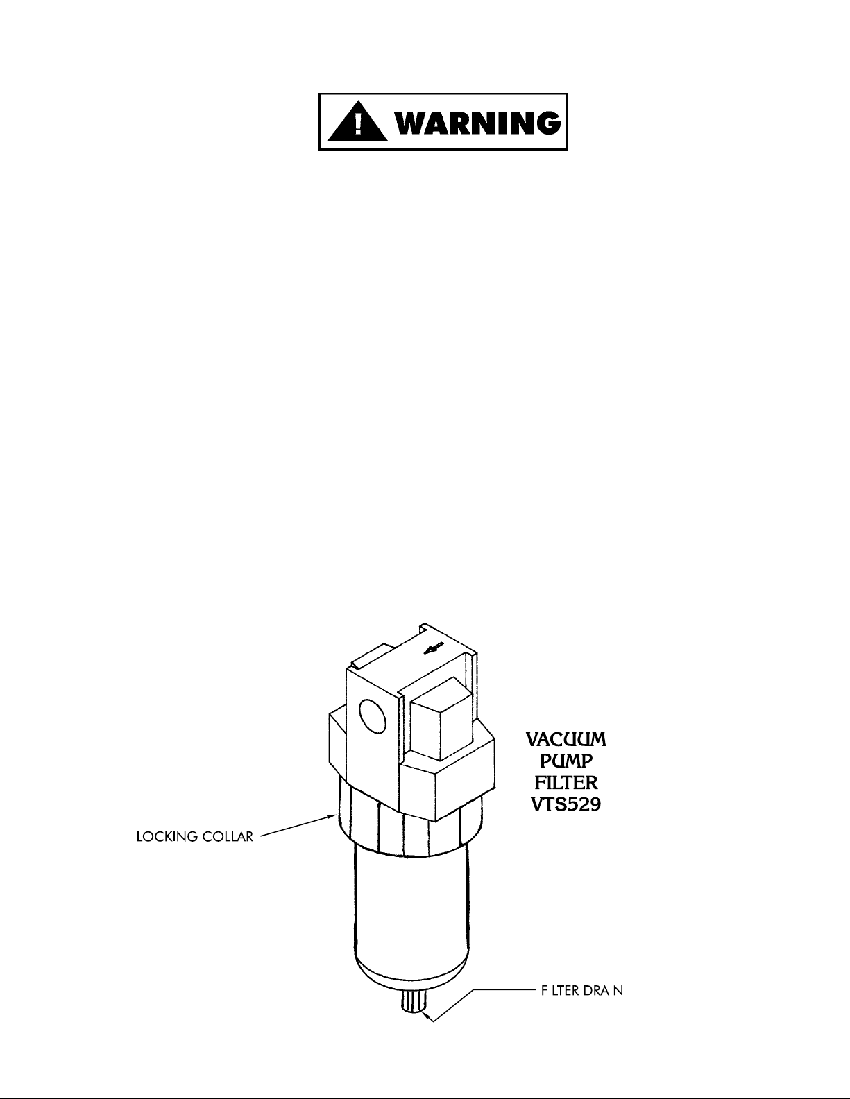
A. PUMP FILTER No. VTS529
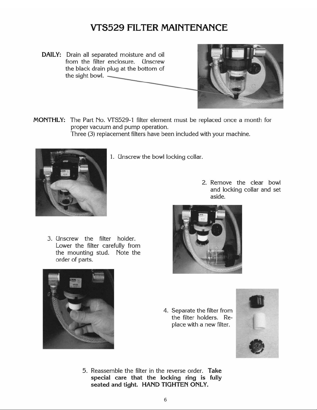
1. Check filter daily. Filter must be drained before the separated moisture and oil reaches the bottom of the
lower black baffle. Drain by unscrewing the black drain plug in bottom of sight bowl.
2. The filter element No. VTS529-1 should be removed and cleaned monthly.
a. Unscrew the black locking collar.
b. Remove bowl and locking collar.
c. Unscrew the black baffle at the bottom of the filter.
d. Clean bowl and filter element. Reinstall the filter element. Clean bowl with mild soap and water only. Do
not use detergents, cleansing agents, such as acetone, alcohol, benzene or gasoline, which are damaging
to plastic.
e. Lubricate bowl lip to assist initial sealing. Use only mineral based oils or grease. Do not use synthetic oils
or silicones.
5
Page 8
Page 9
Page 10

VACUUM PUMP MAINTENANCE
WARNING: MAKE SURE THE ELECTRIC MOTOR IS PROPERLY GROUNDED AND THE WIRING IS DONE BY
A QUALIFIED ELECTRICIAN FAMILIAR WITH NEMA MG2 SAFETY STANDARDS, NATIONAL ELECTRICAL
CODE AND ALL LOCAL SAFETY CODES.
WARNING: THE MOTOR IS THERMALLY PROTECTED AND CAN AUTOMATICALLY RESTART WHEN THE
OVERLOAD RESETS. ALWAYS DISCONNECT FROM POWER SOURCE BEFORE SERVICING. PERSONAL
INJURY COULD BE THE RESULT.
WARNING: DO NOT USE KEROSENE OR OTHER COMBUSTIBLE SOLVENTS TO FLUSH UNIT. USE ONLY
GAST BRAND AH255 FLUSHING SOLVENT OR EQUIVALENT.
1. CONSTRUCTION: The end plate, body, rotor and all mounting brackets are cast iron. Any moisture that
accumulates in the pump will tend to corrode the interior, especially if it stands idle. The muffler box, on the
front of the unit, is made of aluminum. The vanes are made of hard carbon and are precision ground. They
should last many thousand hours depending on degree of vacuum at which the pump is run.
2. STARTING: CAUTION: NEVER LUBRICATE THIS OILLESS AIR PUMP. The carbon vanes and grease
packed motor bearings require no oil. If the motor fails to start or slows down when under load, shut the unit
off and unplug. Check that the supply voltage agrees with the motor post terminals and motor data name
plate. If the pump is extremely cold, allow it to warm to room temperature before starting.
3. FLUSHING: Should excessive dirt, foreign particles, moisture, or oil are permitted to enter the pump the
vanes will act sluggish or even break. Flushing the pump should remove these materials. There are two
options for performing this operation. Option 1: You will need two pipe nipples at least 4" long with
3
8
" NPT
on one end. 1) Remove the filter elements from the front of the muffler box and screw the nipples in through
the same holes. 2) With the pump running allow about 2 tbsp. of flushing solvent to be ingested into the
vacuum side of the unit. CAUTION: WEAR EYE PROTECTION AND FLUSH IN A WELL VENTILATED
AREA. Repeat the flushing procedure. If it does not remedy the situation, remove the end plate for further
examination. Option 2: Remove the filter elements from the front of the muffler box and carefully remove
the five bolts that hold the muffler box in place (be careful not to damage the gaskets and it may be
necessary to replace them). Tap the box with a small hammer to break it loose. DO NOT PRY WITH A
SCREWDRIVER as the gasket will be damaged. This will allow access to the intake and exhaust ports.
4. DISASSEMBLY: If flushing does not eliminate the problem, remove the six bolts holding the end plate to the
body. Now remove the end plate and the four vanes (do not remove the rotor or loosen any electric motor
through bolts). The vanes could be worn or could require further cleaning. The top clearance (between the
rotor and body) may be adjusted by: 1) loosen body bolts, 2) lightly tap on the pump body and turn the rotor
while setting this clearance to assure all points on the rotor clear the body.
REASONS FOR PROBLEM
LOW HIGH PUMP MOTOR
VAC. PRESS. VAC. PRESS. OVERHEATING OVERLOAD
Filter dirty X X at pump X X
Muffler dirty at pump X X
Vacuum line collapsed X at pump X X
Relief valve set too high X X X X
Relief valve set too low X X
Plugged vacuum line X X at pump at pump X X
Vanes sticking X X
Running at too high RPM X X X X
Vanes worn (replace) X X
Shaft seal worn (replace) X X
Dust or offset powder in pump X X X X
Motor not wired correctly X X X
8
Page 11

VTS1034-1
3
4
HP VACUUM PUMP
9
1 VTS-AK518 Pump body 1 req’d.
+2 VTS-AK513 Vane 4 req’d.
3 VTS-AK511 Pump shroud 1 req’d.
4 VTS-AK514 Pump end plate 1 req’d.
+5 VTS-AK522 Gasket 1 req’d.
6 VTS-AK520 Muffler box 1 req’d.
+7 VTS-AK473 O-ring 2 req’d.
+8 VTS-AK524 Felt 2 req’d.
+9 VTS-AK510 End cap 2 req’d.
10 VTS-AK526 End cap assembly, 8 & 9 2 req’d.
11 VTS-AK512 Rotor 1 req’d.
12 VTS-AD126 Tolerance ring 1 req'd.
NOT SHOWN
+ VTS1034-1K Service kit (consists of 2, 5, 7, 8, 9) –
K479
11 & 12 Should not be replaced in field
Page 12

LUBRICATION FOR GROVE GEAR REDUCER
1. Factory Filling
The speed reducers are oil filled at the factory to the proper level for the standard mounting position. The oil
level should be checked and adjusted (if necessary) prior to operation, using the oil level plug provided and
while the unit is oriented in its operating position.
2. Oil Changing
WHEN CHANGING OIL FOR ANY REASON,
DO NOT MIX DIFFERENT OILS IN THE REDUCER.
OILS SHOULD BE COMPATIBLE WITH
VITON®SEAL MATERIAL.
Therefore, when changing to a different oil, it is recommended that the housing be completely drained and
thoroughly flushed with a light flushing oil prior to refilling with the appropriate lubricant. The oil level should
be rechecked after a short period of operation and adjusted, if necessary.
OIL SHOULD BE CHANGED MORE OFTEN IF THE
REDUCER IS USED IN A SEVERE ENVIRONMENT
(i.e., DUSTY, HUMID)
A. Initial Oil Change
The oil in a new speed reducer should be changed at the end of 250 hours of operation. (30 days for 8
hour per day service, 15 days for 16 hour service, 10 days for 24 hour service.)
All standard reducers ordered from the factory are filled with lubricant to operate within a 30° to 100°F
ambient temperature range.
B. Subsequent Oil Changes
Under normal conditions, after the initial oil change, the oil should be changed after every 2500 hours of
operation, or every six months, whichever occurs first. Under severe conditions (rapid temperature
changes, moist, dirty or corrosive environment) it may be necessary to change oil at intervals of one to
three months. Periodic examination of oil samples taken from the unit will help establish the appropriate
interval.
C. Synthetic Oils
Synthetic lubricants can be advantageous over mineral oils in that they generally are more stable, have a
longer life, and operate over a wider temperature range. These oils are appropriate for any application but
are especially useful when units are subjected to low start-up temperatures or high operating
temperatures. Use of synthetics can cause problems if they are not compatible with the seals or the
conventional lubricants they replace. For continuous duty at normal ambient temperatures (-10°F to
105°F) we recommend the use of Mobile SHC 634
which is compatible with the standard compounded oil
shipped in our product and the Viton® seal material used through size 252.
3. Overfilling or Underfilling
If a speed reducer is overfilled with oil, the energy used in churning the excessive oil can result in overheating.
If this occurs, shut down the drive, remove the oil level plug and allow oil to drain until oil ceases to drain
from the level hole, reinstall the oil level plug and restart the drive. if the speed reducer is underfilled, the
resultant friction can cause overheating and possible damage. If this occurs, fill the speed reducer to the oil
level plug hole and check the gearing for excessive wear. NOTE: Oil capacity is 1¾ pints
.
4. Oil Seals
Although the speed reducer uses high quality oil seals and precision ground shafts to provide a superior seal
contact surface, it is possible that circumstances beyond the speed reducer's control can cause oil seal
leakage (damage during shipment or installation, etc.). When replacing a shaft oil seal, using the following
suggestions will help to insure leak-free operation and long seal life.
A. When installing a new seal, cover the keyway and any other surface discontinuity with smooth tape to
protect the seal lip from being damaged.
B. A sealant should be used between the O.D. of the seal and the I.D. of the bore into which the seal is
installed. The seal bore should also be free of any burrs, nicks, or scratches.
C. Be sure that the seal is not cocked in the seal bore. The outer face of the seal should be flush with the
surface into which it is mounted.
10
Page 13

VTS512-1 GROVE GEAR REDUCER
LUBRICATION AND MAINTENANCE
AFTER SERIAL No. VT3
VIEW IS FROM OPPOSITE END OF DRUM
LUBRICANTS FOR VTS512-1 GROVE GEAR WORM REDUCER
The precision-made gears and bearings in Grove Gear Speed Reducers require high-grade lubricants of the proper viscosity to maintain trouble-free performance. For best results, use lubricants
on the following chart for worm gear reducers.
Manufacturer 30° to 100°F Ambient Temperature
AGMA Compounded No. 7
50° to 125°F Ambient Temperature
AGMA Compounded No. 8
Amoco Oil Co. Worm Gear Oil Cylinder Oil #680
Chevron USA, Inc. Cylinder Oil #460X Cylinder Oil #680X
Exxon Co. USA Cylesstic TK-460 Cylesstic TK-680
Gulf Oil Co. Senate 460 Senate 680D
Mobile Oil Corp. 600 W Super Cylinder Extra Hecla Super
Shell Oil Co. Valvata Oil J460 Valvata Oil J680
Sun Oil Co. Gear Oil 7C Gear Oil 8C
Texaco Honor Cylinder Oil 650T Cylinder Oil
Union Oil Co. of CA Steaval A Worm Gear Lube 140
Standard factory-installed lubricant is Mobile Oil Corp. 600 W Super Cylinder Oil (AGMA7).
Some gear lubricants contain E.P. additives that can be corrosive to gear bronze material. Avoid
lubricants that are compounded with sulfur and/or chlorine.
11
Page 14

TO PROGRAM TIMER
Part No. VTS511
Key Sequence Display
Press SET Key SEt1 prompt is displayed
Press SET Key Setpoint 1 (tumble time) is displayed with
flashing digit indicating that setpoint can be
changed.
Change using Arrow Keys New setpoint value is displayed.
Press ENT Key New setpoint entered into memory.
Press SET Key SEt2 prompt is displayed.
Press SET Key Setpoint 2 (relax time) is displayed with
flashing digit indicating that setpoint can be
changed.
Change using Arrow Keys New setpoint value is displayed.
Press ENT Key New setpoint entered into memory.
Press SET Key rEPT prompt is displayed.
Press SET Key Cycle repeat is displayed with flashing digit
indicating that setpoint can be changed.
Change using Arrow Keys New setpoint value is displayed
Press ENT Key New setpoint entered into memory.
Press ENT Key Press RST key
Timing cycle is entered into memory
NOTE: The ENT must be pressed after any variable data has been entered.
EXAMPLES SETTINGS:
Tumble for 15 minutes
Relax for 10 minutes
Repeat 3 times
SEt1 = 15.00
SEt2 = 10.00
REPt = 0003
Total tumble time 45.00 minutes
Total relax time 30.00 minutes
Tumble for 45 minutes
No relax time
Repeat 1 time
SEt1 = 45.00
SEt2 = 00.00
REPt = 0001
Total tumble time 45.00 minutes
12
Page 15

TIMER PROGRAM NOTES
13
Page 16

VTS1053
PHOTOELECTRIC EYE
OPERATING INSTRUCTIONS
Starting Operation
1. Open the cover and guard of the sensor; make sure that no dirt enters the device.
2. Select switching function:
L.ON: Light-switching if light received, output (Q) switches.
D.ON; Dark-switching if light interrupted, output (Q) switches.
WT 260-R and -S only: Light-switching: Relay 1x u, separated galvanically.
3. With following connectors only:
Connect and secure cable receptacle tension-free
Only in versions with terminal clamp area:
Loosen ½" PF screwed connection, remove sealing plugs.
Cable outlets downward or to the back. Pass the dead power supply line through and connect the sensor
according to connection diagram.
4. Close the protective cap.
Mount the sensor using the mounting holes and align it roughly.
Connect the operating voltage to the sensor (see Type imprint).
Check scanning distance, and compare with characteristic in diagram (x = scanning distance, y = operating
reserve).
Reflectance: 6% = black, 18% = gray, 90% = white (based on standard white to DIN 5033).
Aligning light reception:
Position the object. Align the WT 260 with the object. Turn the knob >SENS, <to max. When the light
reception is optimal, the switching output switches into the state set in.
If no or too little light is received, realign the photoelectric proximity switch with the object and check the
application conditions.
5. Setting the sensitivity (SENS):
Remove the object. The switching output switches (Pos. A = Max).
When there is interference from the background:
Turn the knob (turning range 270º) in the direction of min. (e.g. position A). Set the rotary knob to min.
Position the object. Turn the knob in the direction of max. until the switching output switches (e.g.
position B).
If position B < position A:
Select the middle setting (e.g. position C). Check overall operation. If operation is OK, setting is
completed. IF operation is not OK, check the application conditions and realign.
If position A < position B:
Background influence is excessive. Check the application conditions and realign. Check sealing faces,
seals, and screwed joints, then replace and screw down cover.
Maintenance
SICK photoelectric switches do not require any maintenance.
We recommend that you clean the optical interfaces and check the screw connections and plug-in
connections at regular intervals.
14
See #5, Page 15.
See #1, Page 15.
Page 17

VTS1053
Photoelectric Eye Operating Instructions
15
This tumbler contains a photo sensor
light beam as a safety barrier. If a
person or object blocks the beam, the
machine will STOP.
Clear the photo sensor beam & press
the start button to resume operation.
Page 18

Page 19

17
Page 20

DRUM ASSEMBLY
18
Item
No. Description
HHS025S Hex head screw ¼-20´½SS
ST97 Drain cap wrench
VTS1081-1 Drum cover handle
VTS1083-8 Lid latch
VTS1083-9 Latch keeper plate
VTS361 Drain tube
VTS363-1 Drain cap
VTS364 Drive shaft key
VTS562-3 Drum weldment
VTS566-5 Drum cover
VTS568-1 Drum cover gasket
VTS569-1 Mounting block
VTS7152 Ball valve S.S.
VTS7194 Quick coupling S.S.
Page 21

Page 22

20
Item
No. Description
VTS1034-1 Vacuum pump – ¾ HP
VTS1103 Reducer bushing ½
´
3
8
– S.S.
VTS1112 Shim washer .125 Thk
´
.875 ID
´
1.375 OD
VTS1113 Shim washer .093 Thk
´
.875 ID
´
1.375 OD
VTS1114 Male hose barb
3
8
hose
´
½ NPT
VTS529 Filter (06F21BC)
VTS529-1 Filter element
VTS585 Elbow, 90 degree street,
3
8
", brass
VTS586 Nipple, 3 inch,
3
8
pipe, brass
VTS587 Nipple, 2 inch,
3
8
pipe, brass
VTS591 Nipple 1
3
8
´
3
8
pipe – brass
VTS592 Elbo – 90º
´
3
8
pipe – brass
Item
No. Description
VTS7002 Vacuum gauge
VTS7117 Tee barb – plastic
3
8
´
3
8
´
3
8
VTS7118 Straight barb – brass ¼ FPT
´
3
8
VTS7132 Washer – a luminum 1
3
16
O.D.
´
11
16
I.D.
VTS7155-9 Vacuum hose – 9 inch
VTS7155-10 Vacuum hose – 10 inch
VTS7155-15 Vacuum hose – 15 inch – Nylobrade
VTS7155-19 Vacuum hose – 19 inch
VTS7156 Hose clamp
VTS7159 90 degree elbow – S.S.,
3
8
FPT
´
3
8
FPT
VTS7214 Hose barb – brass
3
8
MPT
´
3
8
Page 23

21
Item
No. Description
VTS1036-2 Drum Weldment
VTS1049 Control Box Cover
VTS7002 Vacuum gauge – glycerin filled
VTS7116 90º elbow
3
8
MPT
´
3
8
FPT – SS
VTS7118 Straight barb ¼ FPT
´
3
8
– brass
VTS7132 Washer – aluminum
1
3
16
O.D.
´
11
16
I.D.
´
1
16
TK
VTS7152 Ball valve – SS
VTS7155-1 Hose w/
3
8
crimped fitting – 38" long
Item
No. Description
VTS7155-9 Vacuum hose – 9 inch
VTS7158 Hose barb
3
8
MPT
´
3
8
´
1
3
8
barb lg
VTS7159 90 degree elbow – S.S.,
3
8
FPT
´
3
8
FPT
VTS7160 90º street ¼ MPT
´
¼ FPT – brass
VTS7172 Vacuum gauge label
VTS7193-B Quick coupler BST-3
VTS7194-B Nipple – quick coupler BST-N3m
VTS7214 Hose barb
3
8
MPT
´
1 barb – brass
Page 24

COMPONENT COVER AND REAR DOOR
22
Item
No. Description
42MC-Y25B7 Pop rivet – aluminum
1
8
´
¼
HHS035S Hex head screw ¼-20
´
5
8
S.S.
PC159 Strain relief fitting – ½ dia.
PC161 Strain relief fitting
7
8
dia
VTS1048 Rear door
Item
No. Description
VTS1053 Photoelectric eye w/bracket
VTS1075 Sight window – 2" dia.
VT460S Model and S/N plate
VT464S Filter label
VTS580 Component cover (NSS)
VTS1053 Photoelectric eye w/bracket only
VTS1053-1 Photoelectric eye assembly complete - 4 wires
VTS1053-2 Photoelectric eye assembly complete - 5 wires
used w/
used w/VTS511 timer
VT492S timer
VTS1075 Sight window - 2” dia.
VT460S Model and S/N plate
VT464S Filter label
VTS580 Component cover (NSS)
Page 25

— NOTES —
23
Page 26

120 VAC WIRING DIAGRAM
24
Page 27

220 VAC WIRING DIAGRAM
25
Page 28

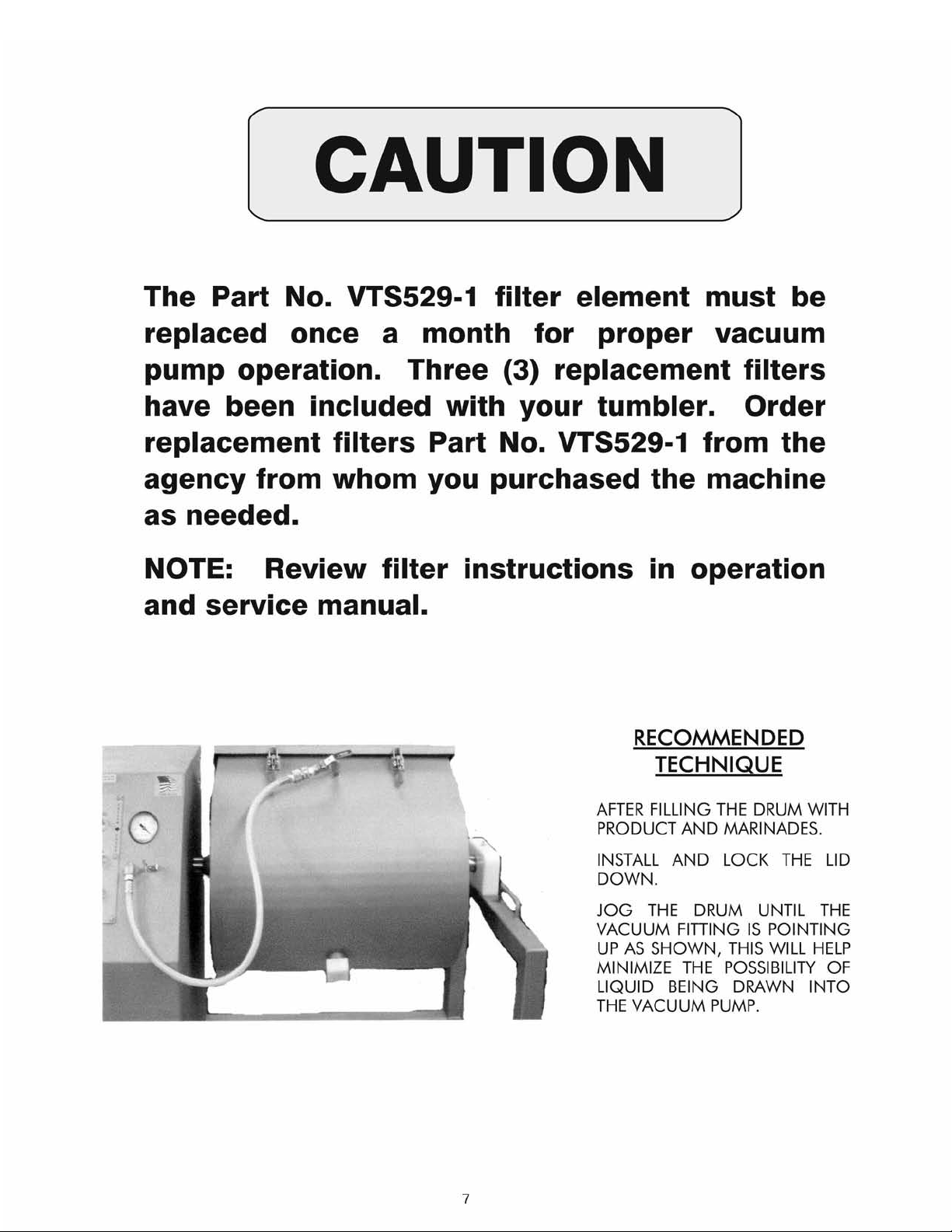
RECOMMENDED
VTS-500 SPARE PARTS
– NOTES –
26
VTS568 Drum cover gasket
VTS363-1 Drain cap
VTS529 Vacuum pump filter
VTS7112 Locking knob
VTS511 Timer
VTS1053 Photoelectric eye
VTS529-1 Filter elements
Page 29

OPERATOR’S SIGNATURE PAGE
WARNING
READ AND UNDERSTAND THIS ENTIRE
MANUAL BEFORE SIGNING BELOW
MY SIGNATURE ATTESTS THAT I HAVE COMPLETELY READ AND UNDERSTAND THIS MANUAL.
I REALIZE THAT THIS MACHINE, IF OPERATED CARELESSLY, CAN CAUSE SERIOUS INJURY TO
MYSELF AND OTHERS.
NAME (PRINT) SIGNATURE
SUPERVISOR’S
INITIALS
DATE
27
Page 30

LIMITED WARRANTY:
WARRANTY: The Biro Manufacturing Company warrants that the BIRO Vacuum Tumbler will be
free from defects in material and workmanship under normal use and with recommended service.
BIRO will replace defective parts, which are covered by this limited warranty, provided that the defective parts are authorized for return, shipping charges prepaid, to a designated factory for inspection and/or testing.
DURATION OF WARRANTY: The warranty period for all parts covered by this limited warranty is
one (1) year from installation/demonstration as advised on the returned warranty registration card,
or eighteen (18) months starting from original factory shipping date, whichever occurs first, except
as noted below.
PARTS NOT COVERED BY WARRANTY: The following are not covered by this limited warranty:
VTS529 vacuum pump inlet filter, VTS568 drum lid gasket. This limited warranty does not apply
to machines sold as used, rebuilt, modified, or altered from the original construction in which the
machine was shipped from the factory. Water contaminated electrical systems and VTS1034-1
Vacuum Pump are not covered under this limited warranty. BIRO is not responsible for electrical
connection of equipment, adjustments to switch components or any other electrical requirements,
which must be performed only by a certified electrician. BIRO is not responsible for service
charges or labor required to replace any part covered by this limited warranty or for any damages
resulting from misuse, abuse, lack of proper or recommended service. Failure to follow drum
loading procedure will result in liquid collecting inside the vacuum pump which voids this warranty.
EXCLUSION OF WARRANTIES AND LIMITATION OF REMEDIES: BIRO gives no warranties
other than those expressly stated in this limited warranty. THE IMPLIED WARRANTY OF MERCHANTABILITY, THE IMPLIED WARRANTY OF FITNESS FOR PROCESSING OF FOOD PRODUCTS, AND ALL OTHER IMPLIED WARRANTIES ARE SPECIFICALLY EXCLUDED. BIRO IS NOT
LIABLE FOR CONSEQUENTIAL OR INCIDENTAL DAMAGES, EXPENSES, OR LOSSES. THE
REMEDIES PROVIDED IN THIS BIRO LIMITED WARRANTY ARE PURCHASER’S SOLE AND EXCLUSIVE REMEDIES AGAINST BIRO.
REGISTRATION CARDS: You must sign, date and complete warranty registration card supplied
with each machine. The warranty registration card must be returned to The Biro Manufacturing
Company for proper registration. If no warranty card is returned to BIRO, the warranty period will
begin from the date the machine was originally shipped from the factory.
HOW TO GET SERVICE:
1. Contact the agency from whom you purchased the machine.
2. Consult the yellow pages of the phone directory for the nearest authorized dealer.
3. Or call BIRO Service Department (419) 798-4451, who will put you in contact with the
nearest service agency.
THE BIRO MANUFACTURING COMPANY
1114 Main Street
Marblehead, Ohio 43440-2099
Ph. 419-798-4451
Fax 419-798-9106
E-mail: service@birosaw.com
Web: http://www.birosaw.com
28
ITEM NO.: VTS583-307
Form No. VTS500-3-06-3 COMM
ITEM NO.: VTS583-307
Form No. VTS500-1-09-4 PPD
 Loading...