

Page 1
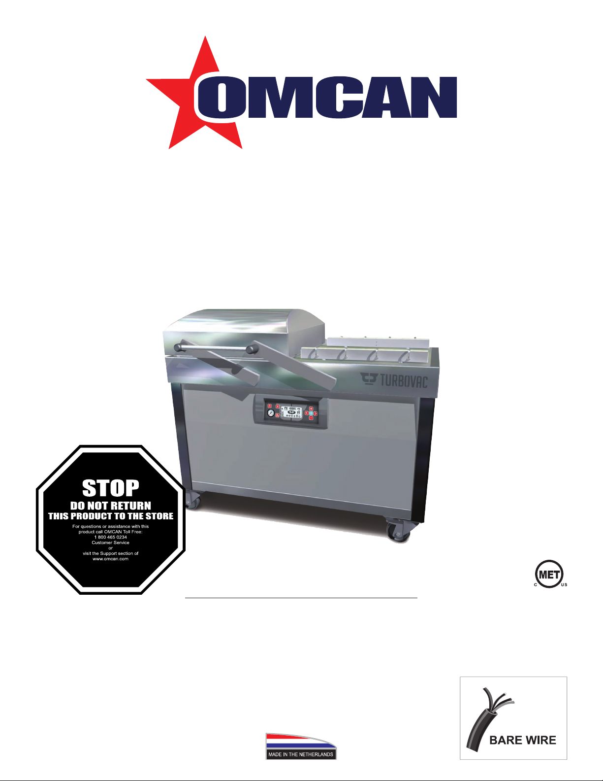
Double Chamber Vacuum Packaging
Models VP-NL-0100-L, 0300-L, 0063-L
Items 50000, 50001, 50002
Instruction Manual
Revised - 04/20/2018
Toll Free: 1-800-465-0234
Fax: 905-607-0234
Email: service@omcan.com
www.omcan.com
Page 2

Table of Contents
Model VP-NL-0100-L / Model VP-NL-0300-L / Model VP-NL-0063-L
Section
General Information
Safety and Warranty
Technical Specications
Installation
Operation
Maintenance
--------------------------------------------------------------------------------------- 6 - 7
--------------------------------------------------------------------------------------- 7 - 14
--------------------------------------------------------------------------------- 14 - 18
--------------------------------------------------------------------------- 3 - 4
--------------------------------------------------------------------------- 4 - 5
Page
-------------------------------------------------------------------------- 6
Troubleshooting
Parts Breakdown
Electrical Schematics
Notes
Warranty Registration
------------------------------------------------------------------------------------------------ 38
----------------------------------------------------------------------------- 19 - 20
---------------------------------------------------------------------------- 21 - 36
---------------------------------------------------------------------------- 37
---------------------------------------------------------------------------- 39
2
Page 3

General Information
Omcan Manufacturing and Distributing Company Inc., Food Machinery of America, Inc. dba Omcan
and Omcan Inc. are not responsible for any harm or injury caused due to any person’s improper or
negligent use of this equipment. The product shall only be operated by someone over the age of 18, of
sound mind, and not under the inuence of any drugs or alcohol, who has been trained in the correct
operation of this machine, and is wearing authorized, proper safety clothing. Any modication to the
machine voids any warranty, and may cause harm to individuals using the machine or in the vicinity of
the machine while in operation.
CHECK PACKAGE UPON ARRIVAL
Upon receipt of an Omcan shipment please inspect for external damage. If no damage is evident on the
external packaging, open carton to ensure all ordered items are within the box, and there is no concealed
damage to the machine. If the package has suffered rough handling, bumps or damage (visible or concealed),
please note it on the bill of lading before accepting the delivery and contact Omcan within 24 hours, so we may
initiate a claim with the carrier. A detailed report on the extent of the damage caused to the machine must be
lled out within three days, from the delivery date shown in the shipping documents. Omcan has no recourse
for damaged products that were shipped collect or third party.
Before operating any equipment, always read and familiarize yourself with all operation and safety
instructions.
Omcan would like to thank you for purchasing this machine. It’s of the utmost importance to save
these instructions for future reference. Also save the original box and packaging for shipping the
equipment if servicing or returning of the machine is required.
--------------------------------------------------------------------------------------------------------------------------------------------------Omcan Fabrication et distribution Companie Limité et Food Machinery d’Amerique, dba Omcan et
Omcan Inc. ne sont pas responsables de tout dommage ou blessure causé du fait que toute personne
ait utilisé cet équipement de façon irrégulière. Le produit ne doit être exploité que par quelqu’un de
plus de 18 ans, saine d’esprit, et pas sous l’inuence d’une drogue ou d’acohol, qui a été formé pour
utiliser cette machine correctement, et est vêtu de vêtements de sécurité approprié. Toute modication
de la machine annule toute garantie, et peut causer un préjudice à des personnes utilisant la machine
ou des personnes à proximité de la machine pendant son fonctionnement.
VÉRIFIEZ LE COLIS DÈS RÉCEPTION
Dès réception d’une expédition d’Omcan veuillez inspecter pour dommages externes. Si aucun dommage
n’est visible sur l’emballage externe, ouvrez le carton an de s’assurer que tous les éléments commandés
sont dans la boîte, et il n’y a aucun dommage dissimulé à la machine. Si le colis n’a subi aucune mauvaises
manipulations, de bosses ou de dommages (visible ou cachée), notez-le sur le bond de livraison avant
d’accepter la livraison et contactez Omcan dans les 24 heures qui suivent, pour que nous puissions engager
une réclamation auprès du transporteur. Un rapport détaillé sur l’étendue des dommages causés à la machine
doit être rempli dans un délai de trois jours, à compter de la date de livraison indiquée dans les documents
d’expédition. Omcan n’a aucun droit de recours pour les produits endommagés qui ont été expédiées ou cueilli
par un tiers transporteur.
3
Page 4

General Information
Avant d’utiliser n’importe quel équipement, toujours lire et vous familiariser avec toutes les opérations
et les consignes de sécurité.
Omcan voudrais vous remercier d’avoir choisi cette machine. Il est primordial de conserver ces
instructions pour une référence ultérieure. Également conservez la boîte originale et l’emballage pour
l’expédition de l’équipement si l’entretien ou le retour de la machine est nécessaire.
--------------------------------------------------------------------------------------------------------------------------------------------------Omcan Empresa De Fabricacion Y Distribucion Inc. Y Maquinaria De Alimentos De America, Inc. dba
Omcan y Omcan Inc. no son responsables de ningun daño o perjuicío causado por cualquier persona
inadecuada o el uso descuidado de este equipo. El producto solo podra ser operado por una persona
mayor de 18 años, en su sano juicio y no bajo alguna inuencia de droga o alcohol, y que este ha sido
entrenado en el correcto funcionamiento de esta máquina, y ésta usando ropa apropiada y autorizada.
Cualquier modicación a la máquina anúla la garantía y puede causar daños a las personas usando la
máquina mientras esta en el funcionamiento.
REVISE EL PAQUETE A SU LLEGADA
Tras la recepcion de un envio Omcan favor inspeccionar daños externos. Si no hay daños evidentes en el
empaque exterior, Habra el carton para asegurararse que todos los articulos solicitados ésten dentro de la
caja y no encuentre daños ocultos en la máquina. Si el paquete ha sufrido un manejo de poco cuidado, golpes
o daños (visible o oculto) por favor anote en la factura antes de aceptar la entrega y contacte Omcan dentro
de las 24 horas, de modo que podamos iniciar una reclamación con la compañia. Un informe detallado sobre
los daños causados a la máquina debe ser llenado en el plazo de tres días, desde la fecha de entrega que se
muestra en los documentos de envío. Omcan no tiene ningun recurso por productos dañados que se enviaron
a recoger por terceros.
Antes de utilizar cualquier equipo, siempre leer y familiarizarse con todas las instrucciones de
operación y seguridad.
Omcan quisiera darles las gracias por la compra de esta máquina. Es de la máxima importancia para
guardar estas instrucciones para referencias en el futuro. También guarde la caja original y el embalaje
para envío del equipo si el mantenimiento o la devolución de la máquina es necesaria.
Safety and Warranty
The manufacturer of this equipment accepts no liability whatsoever for damage or injury caused by failing to
adhere to the directions and instructions in this manual, or through carelessness during the installation, use,
maintenance and repair of the machine identied on the front of this document, or any of its accompanying
options or components.
The owner of the machine is fully responsible at all times for the adherence to the locally applicable safety
regulations and guidelines. Obey all safety instructions and guidelines as provided in this manual.
4
Page 5

Safety and Warranty
INTENDED USE OF THE MACHINE
The machine is designed for vacuum packaging of food or other products for 8 hours a day, 5 days a week.
Any other or extended use is not in accordance with this purpose and the manufacturer accepts no liability for
any resulting damage or injury. Only use this machine while in perfect technical condition in accordance with
the above mentioned purpose.
Safety Measures
The machine is equipped with the following standard safety devices:
• Short-circuit and overload safety.
• Pump fan guards.
All safety devices must be correctly installed and may only be removed to accommodate maintenance and
repair activities by trained and authorized service personnel. The machine may never be operated while safety
measures are incomplete, deactivated or absent. The safety devices may never be by-passed.
1 YEAR PARTS AND LABOR WARRANTY
Within the warranty period, contact Omcan Inc. at 1-800-465-0234 to schedule an Omcan authorized
service technician to repair the equipment locally.
Unauthorized maintenance will void the warranty. Warranty covers electrical and part failures, not
improper use.
Please see www.omcan.com/warranty.html for complete info.
WARNING:
The packaging components are classied as normal solid urban waste and can therefore be disposed of
without difculty.
In any case, for suitable recycling, we suggest disposing of the products separately (differentiated
waste) according to the current norms.
DO NOT DISCARD ANY PACKAGING MATERIALS IN THE ENVIRONMENT!
5
Page 6
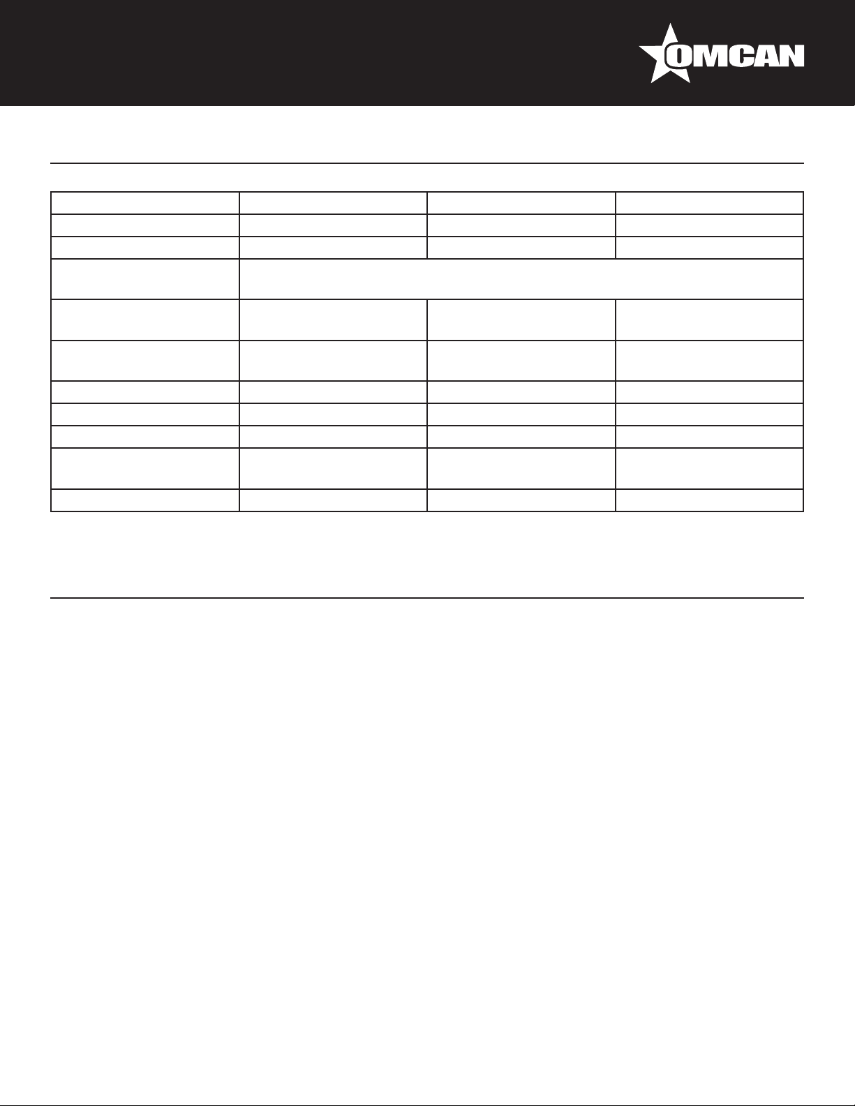
Technical Specications
Model VP-NL-0100-L VP-NL-0300-L VP-NL-0063-L
Seal Length 24.4” / 620mm x 4 32.2” / 920mm x 4 23.6” / 600mm x 4
Vacuum Pump 100 m³ 300 m³ 63 m³
10 Programmable
Control
Maximum Product
Height
Useful Chamber Size
Power Consumption 4.4 kW 6.2 - 9.7 kW 4.4 kW
Electrical 190-240 / 60Hz / 3 220-380V / 60Hz / 3 190-240 / 60Hz / 3
Weight 770 lbs. / 350 kgs. 1584 lbs. / 720 kgs. 528 lbs. / 240 kgs.
Dimensions
Item Number 50000 50001 50002
9” / 230mm 10.6” / 270mm 7” / 180mm
20.5” x 24.4” x 9”
520 x 620 x 229mm
36.2” x 56.7” x 47.4”
920 x 1440 x 1205mm
34.3” x 36.2” x 10.6”
870 x 920 x 270mm
1270 x 2000 x 1245mm
YES
50” x 78.7” x 49”
20” x 24” x 7”
508 x 610 x 178mm
28.3” x 53” x 41”
720 x 1345 x 1041mm
Installation
GENERAL
• Level the machine on a at rm surface.
• Position the machine in such a manner that the pump is unobstructed and properly ventilated.
• Engage the locks on the wheels, if so equipped.
• Check the oil level in the pump; add oil if necessary.
Never operate the machine when the oil level is low.
TURNING ON MACHINE
• If so equipped, like some mobile and double-chamber models, turn on the main power switch on the back
of the machine.
• Push the on/off button on the control panel of the machine.
GAS CONNECTION FOR MAP APPLICATIONS (MODIFIED ATMOSPHERIC PACKAGING)
• Connect the gas supply line to the inlet on the back of the machine.
• Maximum pressure: 1 bar.
• Anchor the gas cylinders securely to prevent them from falling over.
• Make sure that the work area is well-ventilated.
• To assure that you use the appropriate gas for your application, consult your dealer or gas supplier.
• Assure a good connection and use high-quality materials.
6
Page 7

Installation
COMPRESSED AIR CONNECTION FOR ADDITIONAL SEALING PRESSURE
• Additional sealing pressure is usually recommended for MAP applications only.
• The M40-M80 and the L10-L60 models with the option Gas/MAP are standard equipped with a compressed
air inlet.
• Extra sealing pressure is not necessary and not available for the Table-Top, M10, M20, M30.
• Consult your dealer for installation details.
• Maximum pressure: 1 bar.
• Assure a good connection and use high-quality connector.
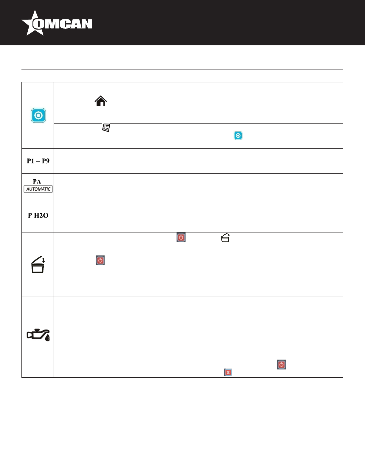
Operation
DIGITAL CONTROL WITH LCD DISPLAY
Some Henkovac vacuum machines have a control system with just one Program (P1). Other machines have
an optional expanded control system, which can accommodate up to 9 custom programs (P1-9).
ONE-PROGRAM CONTROL SYSTEM
Henkovac machines with the One-Program control system can be programmed for the following 2 functions:
1. Vacuum time (seconds).
2. Sealing time (seconds).
• The values for vacuum and sealing times are selected by the user and saved in program P1.
• During operation, the LCD display will show symbols to indicate the active function and the progress of the
packing cycle.
• The actual vacuum pressure is indicated by the analog vacuum gauge.
PLUG AND PLAY
• When turning on the machine for the rst time:
- Running time of the vacuum pump is pre-set at 30-40 seconds and the sealing time at 2 seconds.
Vacuum is indicated on the analog vacuum gauge.
• When turning on the machine after that, program P1 will contain the most-recently used settings.
• The vacuum and sealing times are easily adjusted to match the needs for the application.
7
Page 8
Operation
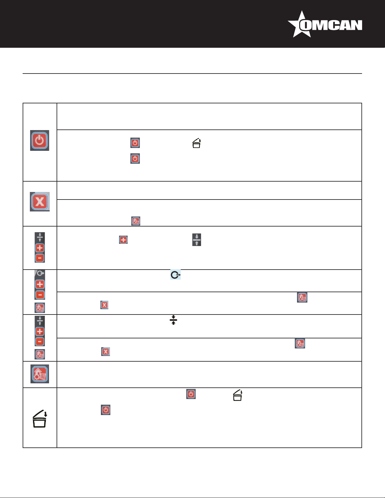
OPERATING THE MACHINE WITH ONE-PROGRAM CONTROL SYSTEM
On: Turns the machine on:
• The machine will start up in the most-recently used program.
• The pump of a machine with a transparent cover will start when the cover is closed.
Off: Turns the machine off:
• When pressing the button once, the symbol will start blinking and the pump will stop
after about 4 seconds.
• When pressing the button a second time, the pump will stop immediately.
• Closing the cover will initiate the cool-down phase; the machine will complete a number of
vacuum cycles before turning off automatically.
Stop-function:
• Stops the machine at any point in the packing cycle and aerates the chamber.
Reset-function:
• While programming, resets the program value to its original setting.
Press the menu button to return to the Home menu
Stops the current function and initiates the next step in the cycle:
• By pressing the of the sealing button , the vacuum function stops and the program jumps
to the sealing function.
• While packing sauce or soup, the package may be sealed as soon as product boiling is
detected.
Entering the desired vacuum time :
By pressing the + or – of the vacuum button, the vacuum time can be increased or decreased.
The selected value is conrmed and saved by pressing the menu button :
• Press the button to reset the original value.
Entering the desired sealing time :
• By pressing the + or – of the sealing button, the sealing time can be increased or decreased.
The selected value is conrmed and saved by pushing the menu button :
• Press the button to reset the original value.
Menu Button:
• Conrms and saves the entered values for vacuum and sealing times.
• Returns to the Home menu.
When turning off the machine with the button, the symbol will start blinking:
• The pump will stop after about 4 seconds.
• Press the button a second time and the pump will stop immediately.
• Close the lid; the machine initiates the cool-down phase and perform a number of vacuum
cycles before turning off automatically.
• These additional cycles allow any moisture in the oil of the pump to evaporate. This increases
the longevity of the machine and minimizes the need for oil changes and pump maintenance.
8
Page 9
Operation
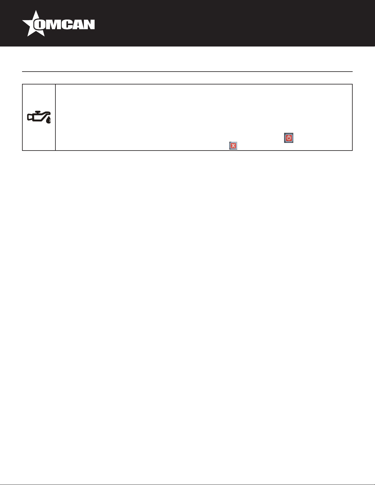
Service Symbol:
• After a number of operating hours or packing cycles, the service symbol will briey appear on
the display when the machine is turned on. In addition, the display indicates how many hours
or cycles remain before an oil change is required.
• Except for regularly changing the oil in the pump (important!), the machine requires little other
routine maintenance.
• To reset the service interval counters after the oil change: Start machine and while the
display shows the hours or cycles, press and hold the button.
TEN-PROGRAM CONTROL SYSTEM
In addition to vacuum and sealing times, Henkovac machines with a Ten-Program control system may be
programmed for several additional functions. Each of the 9 customizable programs is either:
1. Time controlled.
2. Sensor controlled.
TIME-BASED OPERATION (VACUUM GAUGE: MBAR)
• The values for vacuum and sealing time, as well as the values for several optional functions, are selected
by the customer and saved in any of 9 customizable programs P1-9.
• When operating a packaging machine with a time-based program, the actual vacuum pressure is indicated
by the analog vacuum gauge. The number of seconds of vacuum time remaining is shown on the LCD
display.
PLUG AND PLAY
• When turning on a time-based machine for the rst time, it will start up in the PA program AUTOMATIC.
This is a pre-set factory program with 30-40 seconds vacuum time and 2 seconds of sealing time.
• When turning on the machine after that, it will start up in the most-recently used program.
OPTIONAL INSTALLATION OF A SENSOR OR SOFT-AIR
• A machine with a time-based control program can be upgraded to sensor-based operation at a later date
by installing the optional sensor kit.
• The Soft-Air feature can also be installed at a later date by ordering the optional soft-air kit.
SENSOR-BASED OPERATION (DIGITAL DISPLAY: MBAR)
• When operating a packaging machine with a sensor-based program, the actual vacuum pressure is digitally
shown on the LCD display in mbar (standard setting) or in % vacuum.
PLUG AND PLAY
• When turning on a sensor-based machine for the rst time, it will start up in the PA program AUTOMATIC.
This is a pre-set factory program with 5 mbar of vacuum and 2 seconds of sealing time.
• When turning on the machine after that, it will start up in the most-recently used program.
OPTIONAL INSTALLATION OF SOFT-AIR
• The Soft-Air feature can also be installed at a later date by ordering the optional soft-air kit.
9
Page 10

Operation
OPERATING THE MACHINE WITH TEN-PROGRAM CONTROL SYSTEM
On: Turns the machine on:
• The machine will start up in the most-recently used program.
• The pump of a machine with a transparent cover will start when the cover is closed.
Off: Turns the machine off:
• When pressing the button once, the symbol will start blinking and the pump will stop
after about 4 seconds.
• When pressing the button a second time, the pump will stop immediately.
• Closing the cover will initiate the cool-down phase.
• The machine will complete a number of vacuum cycles before turning off automatically.
Stop-function:
• Stops the machine at any point in the cycle and aerates the chamber.
Reset-function:
• While programming, resets the program value to its original setting.
• Press the menu button to return to the Home menu.
Back function:
• While reviewing programmed values, returns to the previous selection.
Stops the active function and initiates the next step in the cycle:
• While the machine is running, exits the active function and jumps to the next step in the cycle.
• While packing sauce or soup, the package may be sealed as soon as product boiling is
detected.
Menu Button:
• Toggles between Home menu and Settings menu .
• Save Function: During programming, conrms and saves the entered program values and
returns to the Home menu.
• Return Function: Returns to the Home menu.
Review program values:
• Cycles through programs P1 to P9, as well as PA and P H2O.
• Displays the programmed value for each function; the function being reviewed will be
blinking.
• Displays the value for the next function.
• Returns to the Home menu.
Adjust program values and turn functions ON/OFF:
• Forward or back; adjusted values are saved right away.
• Increases or decreases function values.
• Turns functions ON/OFF; specic functions, like soft-air, clean cut seal, etc., are turned
either on or off.
• If the function is turned on, the value may be adjusted by pressing the and buttons.
• Resets the original value.
• Saves changes and returns to the Home menu.
10
Page 11
Operation
Multi-Functional button: Performs various functions, depending on the active menu:
Home menu :
• No effect while in the PA program.
• For programs P1-9, displays the entered values.
Settings menu :
• For specic functions, like soft-air, clean cut seal etc., the button is used to turn the function
ON/OFF.
Programs 1 through 9:
• Each program may be customized by turning certain functions on or off and by adjusting the
function values.
PA - Automatic:
• Program with factory settings for vacuum and sealing functions, which is activated when
turning on the machine for the rst time.
P H2O – Program:
• To be used when packing liquids or semi-liquids, like sauces and soups.
• Program jumps to the sealing function as soon as product boiling is detected; this prevents
product loss through spillage and evaporation.
When turning off the machine with the button, the symbol will start blinking on the
LCD display:
• The pump will stop after about 4 seconds.
• Press the button for a second time and the pump will stop immediately.
• Close the lid; the machine will initiate the cool-down phase and perform a number of vacuum
cycles before turning off automatically.
• These additional cycles allow any moisture in the oil of the pump to evaporate. This increases
the longevity of the machine and minimizes the need for oil changes and pump maintenance.
Service Symbol:
• After reaching a certain number of operating hours or packing cycles, the service symbol will
briey appear on the display when turning on the machine. In addition, the display indicates
how many hours or cycles remain before an oil change is required.
• Except for regularly changing the oil in the pump, the machine requires little other routine
maintenance.
• After reaching the service limit, the display will indicate the negative number of exceeded
operating hours or cycles.
• To reset the service interval counters after the oil change: Start machine and while the
display shows the hours or cycles, press and hold the button to reset.
PROGRAMMING THE MACHINE
ONE-PROGRAM CONTROL SYSTEM
• The One-Program control system is standard on the S20, S30, S40, S50, M10, M30 (with 21m3 pump).
• The One-Program control system is time-based.
• The Ten-Program control system (time or sensor) is optional for these models, except for S20.
11
Page 12

Operation
THE ONE-PROGRAM CONTROL SYSTEM PROVIDES ONLY ONE PROGRAM (P1)
• There is no memory to store additional values.
• The machine starts with the values that were most-recently used.
• The pump starts upon closing of the cover and stops when it is reopened.
PROGRAMMABLE FUNCTIONS
The following function values may be customized for P1:
• Vacuum time: in seconds.
• Sealing time: in seconds.
PROGRAMMING
1. Turn the machine on by pressing the on/off button.
a. The factory setting for the vacuum time is 30-40 seconds.
b. The factory settings for the seal time is 2 seconds.
REVIEWING VACUUM TIME AND SEALING TIME
1. Press the button to display the programmed vacuum time the vacuum time is pre-set at the factory.
2. Press the button to display the programmed sealing time the sealing time is pre-set at the factory at 2
seconds.
ADJUSTING VACUUM TIME FOR P1
1. Press twice on the or button.
- After pressing once, the programmed value is displayed.
- After pressing twice, the symbol will start blinking and the value may be adjusted.
2. Save the new value by pressing the menu button.
3. To retain the original value, press the button.
4. Exit the program by pressing the menu button.
ADJUSTING SEALING TIME FOR P1
1. Press twice on the or button.
- After pressing once, the programmed value is displayed.
- After pressing twice, the symbol will start blinking and the value may be adjusted.
2. Save the new value by pressing the menu button.
3. To retain the original value, press the button.
4. Exit the program by pressing the menu button.
TURNING OFF MACHINE
1. Turn the machine off by pressing the button.
2. The symbol on the display will start blinking.
3. Push the button a second time and the pump will stop immediately.
4. If no action is taken the pump turns off after 4 seconds.
5. Close the cover and the machine will initiate the cool-down phase and perform a number of vacuum cycles
12
Page 13

Operation
while the cover stays closed and the machine will turn off automatically after about 15 minutes.
- These cycles are necessary to cool down the machine and to allow any moisture in the oil of the pump to
evaporate.
TEN-PROGRAM CONTROL SYSTEM
• The Ten-Program control system is standard time-based on the M20, M40-M80, L01-L60.
- Sensor-based operation is an option, which can be installed at a later date.
• The Ten-Program control system provides:
- 9 customizable programs (P1-P9).
- Program PA; this is an - Automatic Program – Pre-set at the factory at a vacuum time of 30-40 seconds
(or 5 mbar for a sensor-based program) and a sealing time of 2 seconds.
• Program P H2O for liquid products.
- When turning on the machine, the pump will start. After about 15 minutes of inactivity, the pump will stop
automatically.
PROGRAMMABLE FUNCTIONS
The following functions may be customized for each program P1-P9:
Vacuum time: in seconds or mbar (only with sensor).
Sealing time: in seconds.
Vacuum Plus: on/off, in seconds.
Gassing: on/off, in seconds or mbar (only with sensor).
Clean Cut Controlled (CCC) Seal: on/off, in seconds.
Soft-Air: on/off, in seconds or mbar (only with sensor).
Multi-cycle: on/off, in number of cycles.
REVIEWING FUNCTION VALUES FOR P1-P9
1. Turn the machine on by pushing the button.
2. The most-recently used program will be indicated.
3. All selected functions for this program are indicated at the bottom of the display.
4. To review the values for these functions, push the button; use the button to display each
function value.
5. The values cannot be changed; this can only be done in the Settings menu.
6. Push the button to return to the Home menu.
PROGRAMMING AND ADJUSTING VALUES FOR P1-P9
1. Select the program to be set up or adjusted.
2. Push the menu button to access the Settings menu.
3. All functions for the selected program are indicated at the bottom of the display.
4. Push the button to select the blinking function to be adjusted.
5. Adjust the value of the selected function with the button.
6. Press the button to reset all functions to their original values.
7. Select the next function with the button.
13
Page 14

Operation
8. Press the menu button to save the entered values and to return to the Home menu.
TURNING PROGRAM FUNCTIONS ON/OFF
The following functions can be turned ON/OFF for each program P1-P9:
Vacuum Plus: on/off, in seconds.
Gassing: on/off, in seconds or in mbar (only with sensor).
Clean Cut Controlled (CCC) Seal: on/off, in seconds.
Soft-Air: on/off, in seconds or in mbar (only with sensor).
Multi-cycle: on/off, in number of cycles.
ADJUSTING ON/OFF FUNCTION VALUES
1. Press the menu button to select the Settings menu.
2. Use the button to select the blinking function to be adjusted.
3. Press the button to select the desired value.
4. Press the button to reset all functions to their original values.
5. Select the next function with the button.
6. Push the menu button to store all selected values and to return to the Home menu.
TURNING OFF MACHINE
• Follow the same procedure as for the One-Program control system.
Maintenance
GENERAL
Regular maintenance prevents equipment malfunctions and prolongs the life of the machine. In addition, it
optimizes sanitary conditions.
• Always have a certied Henkovac dealer carry out repair and maintenance activities.
WARNING
• During maintenance activities, always turn the machine off at the main switch and/or unplug it from the
electrical outlet.
ATTENTION
Observe the recommended service intervals. Overdue maintenance may lead to costly repairs and overhauls,
and may void the equipment warranty.
• After reaching a programmed number of operating hours or packing cycles, the service symbol will
briey appear on the display when the machine is started up. In addition, the display will indicate how many
hours or cycles remain before an oil change is required.
14
Page 15

Maintenance
• After passing the service limit, the display will indicate the negative number of excess operating hours or
cycles.
VACUUM PUMP
To protect the vacuum pump, proper maintenance is important. Carry out the following tasks carefully:
• Check the vents and clean as necessary before turning on the machine to assure proper cooling of the
pump.
• When the air lter is saturated with oil, an oil mist may be expelled; replacement of the lter is required.
• Use the cool-down/dehumidication feature. When turning off the machine and closing the cover ,
the pump continues to run for some time. Any moisture in the oil of the pump will evaporate during this
phase. This increases the longevity of the machine and minimizes the need for oil changes and pump
maintenance.
• Check the oil level regularly and add as needed.
• Change the oil when the service symbol appears on the display.
NOTE
To reset the service interval counters after the oil change: Start machine and while the display shows the
hours or cycles, press and hold the button.
ADDING AND CHANGING THE PUMP OIL
WARNING
The operating temperature of the pump is 70° C / 158° F or higher. Wear gloves when servicing the pump or let
it cool off sufciently to prevent injuries.
ADDING OIL
1. Remove the oil ller cap
2. Add oil up to the maximum-level mark; use oil according to DIN 51506, lubrication oil group VC. When in
doubt, consult your dealer.
3. Replace the oil ller cap.
4. After several packing cycles, check the oil level and add as needed.
CHANGING OIL
1. Remove the oil drain plug and drain the oil.
2. Replace the drain plug.
3. Remove the oil ller cap.
4. Add the correct oil up to the maximum-level mark.
5. Replace the oil ller cap.
6. To reset the service interval counters after the oil change: Start machine and while the display shows the
hours or cycles, press and hold the button.
NOTE
Collect the oil to have it processed and recycled according to the locally applicable regulations.
15
Page 16

Maintenance
SEAL BEAMS AND COUNTER BEAMS
To achieve a quality seal, it is necessary that the seal beam and counter beam are in good condition.
1. Clean the seal and counter beams daily with a dry cloth.
2. Replace the Teon tape on the seal beam if damaged and replace the sealing wire if kinked.
3. Replace the silicone rubber seal if it is burned in.
Depending on the type of machine, there are three seal beam versions:
1. Single-seal beam (T2).
2. Stainless steel seal beam.
3. Aluminum seal beam.
SINGLE-SEAL BEAM
REMOVE THE SEALING WIRE AND TEFLON TAPE AS FOLLOWS:
1. Grab the seal beam in the middle and pull it straight up and out of the machine.
2. The beam is held in place by 2 pins; some force may be necessary to loosen the beam.
3. Remove the brown Teon tape that is applied to the seal beam.
4. Remove the two screws on the underside of the seal beam; this releases the sealing wire.
5. Clean the seal beam thoroughly and remove any glue residue off the Teon tape.
NOTES
• Check the condition of the tensioning springs at both ends of the seal beam; replace if necessary.
• These springs maintain tension on the sealing wire.
• Using the seal beam without the springs may cause sealing wires to break.
INSTALL THE SEALING WIRE AND TEFLON TAPE AS FOLLOWS:
1. Position the sealing wire across the beam and fasten it on one side with a small bolt.
2. Apply tension on the wire by pulling it with a pair of pliers.
3. Fasten the wire on the opposite end of the beam with the second bolt and cut the wire to length; the ends
of the sealing wire must be long enough to make electrical contact with the pins in the vacuum chamber.
4. Apply the Teon tape smooth and tight over the seal beam; make sure that the beam is clean and free of
grease.
5. Re-install the beam in the vacuum chamber; check to make sure that the ends of the sealing wire make
contact with the steel pins.
ALUMINUM/STAINLESS STEEL SEAL BEAM
REMOVE THE SEALING AND CUTTING WIRES AS FOLLOWS:
1. Remove the old wires by pulling them loose from the seal beam contacts.
2. Loosen the clamp screws and remove the seal beam from the U-prole.
3. Remove the Teon tape from the seal beam.
4. Remove the mounting plates on both ends of the seal beam by loosening the screws; this releases the
sealing wires and/or sealing and cutting wires.
5. Clean the seal beam thoroughly.
16
Page 17

Maintenance
NOTES
• After removal of the wires, check the strips of ber glass for damage; replace if necessary.
• Check the condition of the tensioning springs at both ends of the seal beam; replace if necessary.
• Using the seal beam without the springs may cause the sealing wires to break.
• Check contact plate for damage; replace if necessary.
INSTALL THE SEALING AND CUTTING WIRES AS FOLLOWS:
1. If necessary, install new strips of ber glass on the seal beam.
2. Insert the new wires behind one of the mounting plates and tighten the screws; make sure that the end of
the wires line up with the bottom edge of the mounting plate.
3. Position the wires across the seal beam and loosely install the second mounting plate.
4. Carefully clamp the seal beam upside down in a bench vice.
5. Pull the wires as tightly as possible with a pair of pliers and secure the second mounting plate by tightening
the screws.
NOTE
1. The wires can be further tightened by slightly loosening the screws of one of the mounting plates.
2. Pull the wires one-by-one tighter with a pair of pliers.
3. Re-tighten the screws after the correct tension has been achieved.
4. Cut the end of the wires ush with the bottom edge of the mounting plate.
5. Apply the Teon tape smooth and tight over the seal beam without creases. Make sure that the beam is
clean and free of grease.
6. Re-install the seal beam in the vacuum chamber and re-connect the wires.
ALUMINUM T-SHAPED SEAL BEAM
REMOVE THE SEALING WIRES AS FOLLOWS:
1. Remove the seal beam from the machine.
2. Remove the Teon tape.
3. Loosen the screws on both sides of the beam; this will release the sealing wires.
4. Clean the seal beam thoroughly.
INSTALL THE SEALING WIRES AS FOLLOWS:
1. Apply new ber glass to the beam if necessary.
2. Place new wires on the beam and fasten them on one side with mounting plates; tighten the screws.
3. Position the wires across the beam.
4. Fasten mounting plates; tighten screws.
5. Carefully clamp the beam in a bench vice.
6. Pull the wires as tightly as possible with a pair of pliers.
7. Secure the mounting plates with the screws.
NOTES
• Check the strip of ber glass for damage and replace if necessary.
• Check the springs and replace if necessary.
• Using the seal beam without the springs may cause the sealing wires to break.
17
Page 18

Maintenance
APPLYING TEFLON TAPE TO SEAL BEAM
1. Position the new Teon tape on the seal beam and cut out the corners.
2. Remove the protective backing from the Teon tape.
3. Apply the new tape to the seal beam; the tape has an adhesive strip on both sides.
4. Slide the seal beam onto the pins in the vacuum chamber (machines with transparent cover).
5. Slide the seal beam in the holder of the cover, tighten the mounting screws, and re-connect the wires
(machines with metal cover).
NOTE
• The Teon tape must not adhere to the tension blocks.
REPLACING SILICONE RUBBER SEAL OF COUNTER BEAM
The rubber seal is clamped in the counter beam. Replace the counter beam seal as follows:
1. Pull the old rubber seal from the groove in the counter beam.
2. Clean the groove.
3. Evenly press the new rubber seal into the groove and make sure that it does not stick out at either end of
the counter beam.
RUBBER SEAL OF VACUUM CHAMBER COVER
To assure that the vacuum chamber is properly sealed, it is important that the rubber seal is in good condition
and is not damaged. Replace the cover seal as follows:
1. Copy the length of the original rubber seal.
2. Pull the original rubber seal from the groove.
3. Clean the groove.
4. Evenly press the rubber seal into the groove; position the ends of the seal tightly against each other to
prevent leakage.
STRUTS, DAMPERS AND SPRINGS
• Machines with transparent covers are equipped with gas struts to open the cover.
• Machines with metal covers are equipped with oil dampers and springs to open the cover.
• Have the struts, dampers and springs checked by your dealer once every 5 years and have them replaced
as necessary.
• Have the gas struts replaced if the lid no longer opens properly.
VACUUM HOSES AND TUBES
• Check the vacuum hoses and tubes for kinks, tears and porosity; replace if necessary.
18
Page 19

Troubleshooting
Fault/Symptom Possible Cause Remedy
Machine does not work. The machine is not plugged in. Plug the machine into the electrical
outlet.
The ground fault safety in the
electrical panel has tripped.
A fuse in the electrical panel is
faulty.
A fuse in the machine is faulty. Consult your dealer.
The motor protection of the
machine is switched off.
The vacuum pump does not run at
full speed.
The vacuum in the package is
insufcient.
The seal is leaking. The package seam is poorly
There is not enough gas in the
bag.
The oil is too thick or
contaminated.
The pump motor runs on two
phases.
The programmed vacuum value is
too high.
The packaging material is of poor
quality.
The product damages the bag. Program a higher value for Soft-
The machine gases the package. Turn off the gassing function.
formed.
The package seam is burnt. Decrease the sealing time.
The opening of the vacuum bag is
contaminated.
The sealing beam is dirty. Clean the sealing beam.
The Teon lining of the sealing
beam is damaged.
The silicon rubber seal in the
counter beam is damaged.
The bag is too small. Select a bigger bag.
The programmed gas level is too
low.
The bag is not correctly positioned
over the gas outlets.
Check the electrical panel.
Check the electrical panel.
Consult your dealer.
Change the oil.
Check the voltage; if correct,
consult your dealer.
Lower the vacuum value in the
program.
Select a better-quality packaging
material.
Air.
Increase the sealing time and/or
reduce the MAP gas pressure.
Try again and make sure that the
opening of the bag stays clean.
Replace the Teon lining.
Replace the silicon rubber seal.
Increase the gas level value.
Adjust the bag position.
19
Page 20

Troubleshooting
The machine does not seal. The bag is not correctly positioned
over the sealing beam.
The sealing wire is broken. Replace the sealing wire.
The thermal safety of the power
supply was tripped.
The electrical contacts of the seal
beam have fouled.
The service symbol appears when
turning on the machine, indicating
the remaining production hours or
cycles.
The service interval counters
have reached their maximum
programmed values.
REFERENCE
Item Number Model Number Description
Vac Pack Machine 24.5” x 20.5” /
50000 VP-NL-0100-L
50001 VP-NL-0300-L
50002 VP-NL-0063-L
620mm x 520mm 100 M3 Pump
10 Program 220/60/3 CSA/UL
Vac Pack Machine 36” x 34” /
920mm x 870mm 300 M3 Pump
10 Program 220/60/3 CSA/UL
Vac Pack Machine 24” x 20” /
610mm x 510mm 63 M3 Pump
10 Program 220/60/3 CSA/UL
Adjust the bag position.
Wait until the safety resets, which
can take half an hour. Decrease
the sealing time.
Remove the seal beam and clean
the pins and contacts with sand
paper.
To reset the service interval
counters after the oil change: Start
the machine and while the display
shows the hours or cycles, press
and hold the “X” button.
Manufacturer Model
Number
L10-LL100
L40-LL300
L60-LL63
20
Page 21

Parts Breakdown
Model VP-NL-0100-L 50000 Lid
21
Page 22

Parts Breakdown
Model VP-NL-0100-L 50000 Workplate
22
Page 23

Parts Breakdown
Model VP-NL-0100-L 50000 Standard Assembly
23
Page 24

Parts Breakdown
Model VP-NL-0100-L 50000 Switch Box
24
Page 25

Parts Breakdown
Model VP-NL-0100-L 50000 Vacuum/Gas Pump
25
Page 26

Parts Breakdown
Model VP-NL-0100-L 50000 Lid
Item No. Description Position Item No. Description Position Item No. Description Position
65680 Tap Lid DA for L10 2 35948 Castle Washer Red Copper M10 for L10 14 65683 Sealbalk A1015 Double Seal for L10 56
15938 Sealbag 4002 L=550mm for L10 3 62734 Bearing Busch Manifold DA for L10 15 35936 Cable Channel 25x30 for L10 58
35920 Castle Washer M8 for L10 4 65682 D1 Deksel for L10 16 62750
35919
35940 Tube STST 10x1x45mm for L10 6 35941
62745 ISO 4017 - M8x55 for L10 11 35864
65681
35918 Castle Washer M10 for L10 13 27814 Hexagon Nut M8 DIN934 A2 for L10 30
Compression Spring Seal Mechanism
for L10
Seal Mechanism Assembly D1/M4-L
for L10
5 35831 Cable Gland M25x1.5 Brass for L10 20 65684
Hexagon Screw M10x25 DIN933 A2
for L10
Hex.Socket Head Cap Screw M5x25
DIN912 A2 for L10
12 62747 Cover for Suction Hole for L10 29
21 62749
25 35872
Acryltape Dubbelzijdig 25mm, L60mm
for L10
Silicone Prole HD Model III 80 Deg
Shore-A for L10
DIN 916 - M8x80 Hexagon Socket Set
Screw for L10
Self Locking Hexagon Nut M8 DIN985
A2 for L10
Workplate
59
61
62
63
Item No. Description Position Item No. Description Position Item No. Description Position
62688 Workplate for L10 1 29997 Brass Hose Coupling 1/4x6 Ext. for L10 23 65687
35821 Spacer Sil.Holder Gas 6mm for L10 2 35272
35822
35820 Holing Block Siliconholder HD-03 for L10 4 62726
35866 O-Ring 27x2.5 for L10 5 62727
65685 Parallel Axle D1 R2 for L10 7 35829 Limit Switch with Cable for L10 29 65688 Hex-Head Bolt - M10x80 for L10 46
62717 Elbow Screwcoupling G 1/4x8 for L10 9 62731
62718
35831 Cable Gland M25x1.5 Brass for L10 11 35041 Hose Clip Klemfa 12.8x14.8mm for L10 32 62728 Support for Gas Supply Unit DA for L10 50
35868 Spring Axle Double Chamber for L10 12 62733
62720 Bearing Busch DA for L10 13 62732
62721 Universal Bracket DA for L10 15 62719 Switchbox Model-I SC-DC for L10 35 65689
62723 Schakelnok DA R2 for L10 18 35861
62724 Knee 1/2 90 F-F AISI 316 for L10 20 27782
35841 Brass Hose Coupling 1/2x13 Ext. for L10 21 65686 Vacuum Valve MB for L10 38 65690 Rood Koper Ring ZCHT 8.5x18 for L10 83
62725 Knee 1/4 F-F 90 Deg AISI316 for L10 22 62739 Adapter for Manifold D4 for L10 39 62587 Reducing Ring 63x40 BU/BI PVC for L10 84
Mounting Screw Holing Block HD-03
for L10
Hoofdschakelaar H220-SE5494 (25A
3-POLIG) for L10
3 35214 Castle Washer M5 for L10 26 62738
10 35865 Castle Washer M4 for L10 31 62729 Gas Supply Unit DA for L10 48
Hex.Socket Head Cap Screw M5x8
DIN912 A2 for L10
ISO 4762 - M4x25 Hexagon Socket Head
Cap Screw for L10
M4x30 Slotted Cheese Head Screw
for L10
Da Montagesteun Eindschakelaar R2
for L10
Mounting Bracket Switch Box POS2
for L10
Mounting Bracket Switch Box POS1
for L10
Hex.Socket Head Cap Screw M5x16
DIN912 A2 for L10
Hexagon Flangenut M5 DIN6923 A2
for L10
25 62736 ISO 4017 - M8x25 for L10 41
27 62735 O-Ring 70x3mm for L10 43
28 62734 Bearing Busch Manifold DA for L10 45
30 35219 Flat Washer M8 D9021 A2 for L10 47
33 35961 Suspension Clip BSA-8/29/33 for L10 51
34 35220
36 62730 Bearing 40x30 for L10 81
37 62722 3-2 Valve DC-XL Assembly for L10 82
Vacuum Transmittor 0-1050MBAR
for L10
Mounting Pin Adapter Manifold DA
for L10
Hexagon Screw M8x10 DIN933 A2
for L10
Hexagon Socket Head Cap Screw
M8x60 for L10
40
42
52
53
26
Page 27

Parts Breakdown
Model VP-NL-0100-L 50000
Item No. Description Position Item No. Description Position Item No. Description Position
65691 Workplate D1 for L10 1 35909 Skiffy Ring 21x37x3mm for L10 13 35214 Castle Washer M5 for L10 40
65692 Deksel D1 for L10 2 62696 04 Control Panel for L10 14 62705 Blokkeerbout Parallelstang DA for L10 44
35881 Closing Plug Silicon Holder for L10 3 30026
65693 Frame D1 for L10 4 65698 Handgreep M EN D1 for L10 16 35219 Flat Washer M8 D9021 A2 for L10 46
65694 Beplating D1 Achter for L10 5 65699 Parallelstang D1 for L10 17 41510 Filler Plate 1 Inch/25mm for L10 47
65695 Beplating D1 Schakelkast for L10 6 65700 Borgplaat Pallelstang for L10 18 65703 Trekveer D1 for L10 48
65696 Beplating D1 Pump for L10 7 65701
62691 Handle Flat ABS Black for L10 8 35868 Spring Axle Double Chamber for L10 21 62709
62692
65697 Silicone Holder D1/M4-L for L10 10 35236 Spring Ring M8 DIN127 A2 for L10 37 35965 Pipe 13x1.5x34mm SS 304 for L10 52
35015 Silicone Prole - 1M for L10 11 35211
35906 Bearing Cover Doublechamber for L10 12 35272
Compression Locker E5-6-012-YY1
for L10
9 65702 Beplating D1 Voor for L10 27 62703 Montagebus Handvat DA for L10 51
Slott.Rais.Counter.Head Screw M4x12
DIN7985 A2 for L10
ISO 4762 - M6x25 Hexagon Socket Head
Cap Screw for L10
Hexagon Screw M8x16 DIN933 A2
for L10
Hex.Socket Head Cap Screw M5x8
DIN912 A2 for L10
15 62706 Zesk.Tapbout M8350 for L10 45
19 62708 Kabeldoorvoer Parallelstang for L10 49
38 27814 Hexagon Nut M8 DIN934 A2 for L10 53
39 35834 Blocking Block Insert Plate for L10 54
Standard Assembly
M10x50 Cylinder Head Cap Screw DIN
912 for L10
50
Switch Box
Item No. Description Position Item No. Description Position Item No. Description Position
65704 DIN-Rail 380mm for L10 1 35316
35303
65705 Wartel M16x1.5 KS for L10 3 35688 Clamp Connector 2.5/2 for L10 13 35317 Ground Terminal PE 6-10 for L10 23
65706 Moer M16x1.5 KS for L10 4 35677 Zekering Keram.5x20 2.5A Traag for L10 14 65711 Sluitplaat PAP PDU 6/10 for L10 24
65707 Moer M20x1.5 KS for L10 5 35555 Cover Switchbox for L10 15 65712 Doorverbinder ZQV 6/2 for L10 25
35376 Cable Gland M20x1.5 Plastic for L10 6 35306 Fuse Clamp 2.5-2/ZSI for L10 16 65713 Wartel M12x1.5 KS for L10 26
35305 End Fent for L10 7 27782
35315 Double Clamp 2.5-2 for L10 8 35559 Micro Cellular Rubber 4mm Black for L10 18 35304 Ground Terminal PE 4-2/3 for L10 28
65708 Sluitplatt Zap ZDU 6-2 for L10 9 65709 Montageplaat 2.5mm2 for L10 19 15772 Contactor 24VAC for L10 29
35323 Endplate Wireconnector for L10 10 35067
Combi-Transformer P200/460V-S24/32V
for L10
2 35687 Wire Clamp 2.5-2/2 AN for L10 12 35318 Wireclamp 6-2/2 AN for L10 22
Closed Contactor AB100-C09KJ400
24VAC for L10
Hexagon Flangenut M5 DIN6923 A2
for L10
Hexagon Flangenut M4 DIN6923-A2
for L10
11 65710 EMBR AB193-ED1*P for L10 21
17 65714 Moer M12x1.5 KS for L10 27
20
27
Page 28

Parts Breakdown
Model VP-NL-0100-L 50000
Item No. Description Position Item No. Description Position Item No. Description Position
65691 Workplate D1 for L10 1 62704 Silicon Bar for L10 25 27814 Hexagon Nut M8 DIN934 A2 for L10 39
65682 D1 Deksel for L10 2 35236 Spring Ring M8 DIN127 A2 for L10 26 62712 Borgplaat Parallelstang R2 for L10 78
65694 Beplating D1 Achter for L10 5 35211
65695 Beplating D1 Schakelkast for L10 6 35272
62691 Handle Flat ABS Black for L10 8 35214 Castle Washer M5 for L10 29 27827 Flat Washer M10 D9021 A2 for L10 81
62692
35906 Bearing Cover Doublechamber for L10 12 62706 Zesk.Tapbout M8350 for L10 31 65735 Suction Tube D1 Assembled for L10 83
35909 Skiffy Ring 21x37x3mm for L10 13 35219 Flat Washer M8 D9021 A2 for L10 32 62714 V-Ring Type V-070-A for L10 84
62696 04 Control Panel for L10 14 41510 Filler Plate 1” / 25mm for L10 33 65736 Reducing Ring 2"- 1.1/4" for L10 85
30026
65698 Handgreep M EN D1 for L10 16 62708 Kabeldoorvoer Parallelstang for L10 35 65737 Elbow 1 1/4 INT/EXT NR92 for L10 87
65732 Parallel Bar D1 for L10 17 62709
35868 Spring Axle Double Chamber for L10 20 62703 Montagebus Handvat DA 37 65738
65702 Beplating D1 Voor for L10 22 35965
Compression Locker E5-6-012-YY1
for L10
Slott.Rais.Counter.Head Screw M4x12
DIN7985 A2 for L10
9 62705 Blokkeerbout Parallelstang DA for L10 30 35444
15 65703 Trekveer D1 for L10 34 35879
Hexagon Screw M8x16 DIN933 A2
for L10
Hex.Socket Head Cap Screw M5x8
DIN912 A2 for L10
M10x50 Cylinder Head Cap Screw DIN
912 for L10
Pipe 13x1.5x34mm Stainless Steel 304
for L10
27 65733 Frame D1-160M3 Vacuum Pump for L10 79
28 65734 Plating Pumpside D1-160M3 for L10 80
36 62711 Elbow 2" BI/BU RVS for L10 88
38 62715
Vacuum/Gas Pump
Hexagon Screw M10x16 DIN933 A2
for L10
Pipe Nipple Half 1.1/4x75 Complete
for L10
Vacuumpump 160-132 230/400-3-50
for L10
M6x45 Hexagon Socket Head Screw
ISO4762 for L10
82
86
89
90
28
Page 29

Parts Breakdown
Model VP-NL-0300-L 50001 Lid
29
Page 30

Parts Breakdown
WorkplateModel VP-NL-0300-L 50001
30
Page 31

Parts Breakdown
Standard AssemblyModel VP-NL-0300-L 50001
31
Page 32

Parts Breakdown
Model VP-NL-0300-L 50001 Lid
Item No. Description Position Item No. Description Position Item No. Description Position
62689 Lid for L40 1 62746 Seal Mechanism D4 Assembly for L40 14 27814 Hexagon Nut M8 DIN934 A2 for L40 25
65684
65680 Tap Lid DA for L40 5 62734 Bearing Busch Manifold DA for L40 16 35872
62744 Sealzak E-493/E503/A-5000 for L40 6 35948 Castle Washer Red Copper M10 for L40 17 62749
35920 Castle Washer M8 for L40 7 35831 Cable Gland M25x1.5 Brass for L40 20 35936 Cable Channel 25x30 for L40 30
35919
35940 Tube STST 10x1x45mm for L40 9 35864
62745 ISO 4017 - M8x55 for L40 13 62747 Cover for Suction Hole for L40 24
Silicone Prole HD Model III 80 Deg
Shore-A for L40
Compression Spring Seal Mechanisim
for L40
3 35918 Castle Washer M10 for L40 15 62748 Sealbeam A1060 Double Seal for L40 26
Self Locking Hexagon Nut M8 DIN985
A2 for L40
Din 916 - M8x80 Hexagon Socket Set
Screw for L40
8 35941
Hexagon Screw M10x25 DIN933 A2
for L40
Hex.Socket Head Cap Screw M5x25
DIN912 A2 for L40
21 62750
22
Acryltape Dubbelzijdig 25mm, L60mm
for L40
Workplate
27
28
31
Item No. Description Position Item No. Description Position Item No. Description Position
62688 Workplate for L40 1 29997 Brass Hose Coupling 1/4x6 EXT. for L40 20 35219 Flat Washer M8 D9021 A2 for L40 37
35820 Holing Block Siliconholder HD-03 for L40 4 62725 Knee 1/4 F-F 90Deg AISI316 for L40 21 35965
35866 O-Ring 27x2.5 for L40 5 35272
35821 Spacer Sil.Holder Gas 6mm for L40 6 35214 Castle Washer M5 for L40 24 62732
62716 D4 Parallel-Axle for L40 7 62726
62717 Elbow Screw Coupling G 1/4x8 for L40 9 62727
62718
35831 Cable Gland M25x1.5 Brass for L40 11 35843 Hose Coupling 1/2x10 EXT. for L40 28 62735 O-Ring 70x3mm for L40 46
62719 Switchbox Model-I SC-DC for L40 12 62728 Support for Gas Supply Unit DA for L40 29 62736 ISO 4017 - M8x25 for L40 47
62720 Bearing Busch DA for L40 13 62729 Gas Supply Unit DA for L40 30 62737 ISO 4017 - M8x80 for L40 48
62721 Universal Bracket DA for L40 14 35961 Suspension Clip BSA-8/29/33 for L40 31 62738
35861
62722 3-2 Valve DC-XL Assembly for L40 16 62731
62723 Schakelnok DA R2 for L40 17 35865 Castle Washer M4 for L40 34 62740 Vacuum Valve D4 for L40 53
62724 Knee 1/2 90 F-F AISI 316 for L40 18 35411 Hexagon Nut M4 DIN934 A2 for L40 35 35220
35841 Brass Hose Coupling 1/2x13 EXT. for L40 19 27814 Hexagon Nut M8 DIN934 A2 for L40 36 62741
Hoofdschakelaar H220-SE5494 (25A
3-POLIG) for L40
Hex.Socket Head Cap Screw M5x16
DIN912 A2 for L40
10 35829 Limit Switch with Cable for L40 27 62734 Bearing Busch Manifold DA for L40 44
15 62730 Bearing 40x30 for L40 32 35822
Hex.Socket Head Cap Screw M5x8
DIN912 A2 for L40
ISO 4762 - M4x25 Hexagon Socket Head
Cap Screw for L40
M4x30 Slotted Cheese Head Screw
for L40
Da Montagesteun Eindschakelaar R2
for L40
23 27782
25 62733
26 35868 Spring Axle Double Chamber for L40 42
33 62739 Adapter for Manifold D4 for L40 52
Pipe 13x1.5x34mm Stainless Steel 304
for L40
Hexagon Flangenut M5 DIN6923 A2
for L40
Mounting Bracket Switch Box POS1
for L40
Mounting Bracket Switch Box POS2
for L40
Mounting Pin Adapter Manifold DA
for L40
Mounting Screw Holing Block HD-03
for L40
Hexagon Screw M8x10 DIN933 A2
for L40
Vacuum Transmitter with Earth Connection for L40
38
39
40
41
50
51
55
100
32
Page 33

Parts Breakdown
Model VP-NL-0300-L 50001
Item No. Description Position Item No. Description Position Item No. Description Position
62688 Workplate for L40 1 35868 Spring Axle Double Chamber for L40 18 62708 Kabeldoorboer Parallelstang for L40 33
62689 Lid for L40 2 62700 Pull Spring D4 for L40 19 35965
65739 Frame for L40 4 27814 Hexagon Nut M8 DIN934 A2 for L40 20 62709
62691 Handle Flat ABS Black for L40 5 62701 Brass Coupling 2x50 EXT for L40 21 35219 Flat Washer M8 D9021 A2 for L40 38
62692
62693 Beplating D4 Achter for L40 7 62703 Montagebus Handvat DA for L40 24 62711 Elbow 2" BI/BU RVS for L40 41
62694 Plating Pump Side D4 for L40 8 62704 Silicon Bar for L40 25 62712 Borgplaat Parallelstang R2 for L40 84
62695 Beplating D4 Schakelkast for L40 9 35236 Spring Ring M8 DIN127 A2 for L40 26 62713 Suction Tube GK293 Assembled for L40 89
35909 Skiffy Ring 21x37x3mm for L40 10 35211
62696 04 Control Panel for L40 11 35272
30026
62697 Handgreep D4 for L40 13 62705 Blokkeerbout Parallelstang DA for L40 30 62715
62698 Parallelstang D4 R2 for L40 14 62706 Zesk.Tapbout M8350 for L40 31
35906 Bearing Cover Doublechamber for L40 17 62707 Insertplate D4 for L40 32
Compression Locker E5-6-012-YY1
for L40
Slott.Rais.Counter.Head Screw M4x12
DIN7985 A2 for L40
6 62702 Beplating D4 Voor for L40 22 62710 RA_0302_D for L40 40
Hexagon Screw M8x16 DIN933 A2
for L40
Hex.Socket Head Cap Screw M5x8
DIN912 A2 for L40
12 35214 Castle Washer M5 for L40 29 35444
27 62714 V-Ring Type V-070-A for L40 90
28 27827 Flat Washer M10 D9021 A2 for L40 91
Standard Assembly
Pipe 13x1.5x34mm Stainless Steel 304
for L40
M10x50 Cylinder Head Cap Screw DIN
912 for L40
Hexagon Screw M10x16 DIN933 A2
for L40
M6x45 Hexagon Socket Head Screw
ISO4762 for L40
34
35
92
93
33
Page 34

Parts Breakdown
Model VP-NL-0063-L 50002
34
Page 35

Parts Breakdown
Model VP-NL-0063-L 50002
Item No. Description Position Item No. Description Position Item No. Description Position
35423 Vacuum Cover Complete for L60-LL63 0010 35828
35290 Sight Glass (380x280x20) for L60-LL63 0020 35452 Adjusting Ring 30mm for L60-LL63 1120 35901 Hose Clip ABA 11-17mm for L60-LL63 1550
35105
35299
35882 Plug GN-340 for L60-LL63 0050 35842 Blind Plug 3/8" MS/VN for L60-LL63 1150 30005
35860
35298 Cable Gland M20x1,5 Brass for L60-LL63 0070 35960
35859
35875
35886
35865 Castle Washer M4 for L60-LL63 0140 35883
35300
35947
35436 Shaft Journal Cover for L60-LL63 0180 35464 Filter Gauze Clip Ring for L60-LL63 1240 35492
35906
35438 Parallel Rod for L60-LL63 0200 35466 PVC Nipple BEA 40x32x1 for L60-LL63 1270 35494 Silicon Holder for L60-LL63 3035
35439
35440
35441 Vacuum Chamber Complete for L60-LL63 1010 35864
35442
27827 Flat Washer M10 D9021 A2 for L60-LL63 1030 35956 Non-Return Valve 1/2 for L60-LL63 1420 27836
35444
35445 Parallel Axle for L60-LL63 1050 35867
35446
35918 Castle Washer M10 for L60-LL63 1070 30015
35448 Support Bearing for L60-LL63 1080 35962
35870
35450 Switch Disc 3 for L60-LL63 1100 34998 Flat Washer M4 D9021 A2 for L60-LL63 1530 27788
Sil.Prole Lid Gasket 8mm
60°SH/25MTR for L60-LL63
Handle GN-565-26-192-SW 800 for
L60-LL63
Hex.Socket Head Cap Screw M12x35
Din912 A2 for L60-LL63
Spring Ring Cheese Head M12 Din7980
A2 for L60-LL63
Sealing Washer 0251796/0251797 for
L60-LL63
Slotted Cheese Head Screw M4x8 A2
Din84 for L60-LL63
Hexagon Screw M8x20 Din933 A2 for
L60-LL63
Castle Washer Red Copper M8 for
L60-LL63
Bearing Cover Double Chamber for
L60-LL63
Clamping Prole Parallel Rod for
L60-LL63
Hex.Socket Head Cap Screw M8x30
Din912 A2 for L60-LL63
Clamping Plate Vacuum Chamber for
L60-LL63
Hexagon Screw M10x16 Din933 A2 for
L60-LL63
Hex.Socket Head Cap Screw M10x30
Din912 VZ for L60-LL63
Bearing Ring PAF-20115-P10 for
L60-LL63
0030 35255
0040 35832 Elbow Coupling 10x1/4" for L60-LL63 1140 27786 Flat Washer M6 D9021 A2 for L60-LL63 1570
0060 35254 Reducing Nipple 1/2"x3/8" for L60-LL63 1160 27837 Hose (O2) Drago 6x13 for L60-LL63 1600
0080 35957
0100 35238
0130 35851
0150 35853 Decompress Filter 1/2'' for L60-LL63 1220 35876
0170 35463 Insert Plate for L60-LL63 1230 35491 Sealing Mechanism for L60-LL63 3010
0190 35465 Filter for L60-LL63 1250 35493 Silicon Holder for L60-LL63 3030
0210 35467
0220 35829 Limit Switch with Cable for L60-LL63 1350 35928
1020 35832 Elbow Coupling 10x1/4" for L60-LL63 1400 35352
1040 35890
1060 35950 3-Way Valve for L60-LL63 1480 62683 Seal Beam DS/1/655 for L60-LL63 3100
1090 35477
Switch Plate Double Chamber for
L60-LL63
Distribution Block 4DVB/VP 3/8"-1/4"-4
for L60-LL63
T-Piece 1/2x1/2x1/2 BU/BU/BI for
L60-LL63
Gas Valve for Gas Distribute Pot for
L60-LL63
Vacuum Valve without Decomp.Head
32mm for L60-LL63
Decompress Head Vacuum Valve 32mm
for L60-LL63
T-Screw-in Hose Coupling 1/8"x6 Ext.
for L60-LL63
PVC Tube Round 32 L=80mm for
L60-LL63
Hex.Socket Head Cap Screw M5x25
Din912 A2 for L60-LL63
Air Pressure Hose Blue 10x8 for
L60-LL63
Blind Stopper + O-Ring 1/4" MS/VN for
L60-LL63
Square Hose Coupling 1/4"x6 Ext. for
L60-LL63
Square Hose Coupling 1/4"x8 Ext. for
L60-LL63
Adj.Sxrew/Soc.Head M4x20 Din916 A2
for L60-LL63
1110 35411
1130 35861
1170 35881 Closing Plug Silicon Holder for L60-LL63 1610
1180 35837
1190 35836 Gas Nozzle Universal for L60-LL63 1630
1200 35874 3-Way Valve Soft-Air New for L60-LL63 1640
1210 27820
1280 35822
1360 35497 Pressure Beam for L60-LL63 3060
1460 35500
1475 35501
1510 62684 Seal Beam TS/1/655 for L60-LL63 3110
1520 62685 Seal Beam S2/1/655 for L60-LL63 3115
1525 62686 Seal Beam 8mm/1/655 for L60-LL63 3120
Hexagon Nut M4 Din934 A2 for
L60-LL63
Hex.Socket Head Cap Screw M5x16
Din912 A2 for L60-LL63
Hexagon Screw M6x12 Din933 A2 for
L60-LL63
Hexagon Nut M8x1 Low Din439B for
L60-LL63
Right Hose Coupling 1/8"x6 Ext. for
L60-LL63
Single Banjo Bolt 1/8" for L60-LL63 1660
Spacer Sil.Holder Gas 35mm for
L60-LL63
Mounting Screw Holing Block HD-03 for
L60-LL63
Cable Clip 1x10mm Din72571 for
L60-LL63
Cable Clamp 1x12mm Din7257 for
L60-LL63
Connecting Piece T-Piece 6mm for
L60-LL63
Hexagon Screw M8x70 Din933 A2 for
L60-LL63
Hexagon Screw M8x70 + M4 for
L60-LL63
Adj.Screw/Soc.Head M6x25 Din916 A2
for L60-LL63
1540
1560
1580
1620
1650
3020
3040
3050
3070
3080
3085
3090
3130
35
Page 36

Parts Breakdown
Model VP-NL-0063-L 50002
Item No. Description Position Item No. Description Position Item No. Description Position
35820
35866 O-Ring 27x2.5 for L60-LL63 3150 35375 Nut M20x1.5 MS for L60-LL63 4130 35398
35509
35918 Castle Washer M10 for L60-LL63 3180 35920 Castle Washer M8 for L60-LL63 4150 35400
35920 Castle Washer M8 for L60-LL63 3190 35539
35512
35513 Vacuum Bag Holder for L60-LL63 3210 35844
35105
34998 Flat Washer M4 D9021 A2 for L60-LL63 3230 35861
35933
35015
30005
27824 Castle Washer M6 for L60-LL63 3590 35389
35520 Tube STST 10x1x60mm for L60-LL63 3600 35390 Pipe Nipple Half 1/2 1" for L60-LL63 5060 34998 Flat Washer M4 D9021 A2 for L60-LL63 9160
35521 Seal Bag 2'' L=480mm for L60-LL63 3620 27814 Hexagon Nut M8 Din934 A2 for L60-LL63 5070 35411
35353
35523 Bottom Section for L60-LL63 4000 35219 Flat Washer M8 D9021 A2 for L60-LL63 5090 15943 Vacuum Meter 40mm for L60-LL63 9190
35369
35979 Spring Control Box for L60-LL63 4020 62687
35219 Flat Washer M8 D9021 A2 for L60-LL63 4030 27782
35920 Castle Washer M8 for L60-LL63 4040 35555 Cover Switch Box for L60-LL63 8020 35416 Plug Blac R6 for L60-LL63 9320
35220
27814 Hexagon Nut M8 Din934 A2 for L60-LL63 4060 35557 Valve Cord CC2-06 for L60-LL63 8240 15712
35871 Stud M8x160 DK for L60-LL63 4070 35329 Pump Cord CM4-09 for L60-LL63 8250 27795 Sticker Tension Triangle for L60-LL63 9420
35965
35532 Tension Spring for L60-LL63
35533 Hexagon Screw M8x400 A2 for L60-LL63 4100 35395 Control Turbovac Basic for L60-LL63 9011 35224 Sticker 98x65 Yellow for L60-LL63 9450
35868
Holing Block Silicon Holder HD-03 for
L60-LL63
Tube Alu 10x1mm L=540mm for
L60-LL63
Compression Spring Sealing Mechanism
for L60-LL63
Sil.Prole Lid Gasket 8mm
60°SH/25MTR for L60-LL63
Slotted Cheese Head Screw M4x16 A2
Din84 for L60-LL63
Silicon T-Prole 40º Shore - 25m for
L60-LL63
Hexagon Screw M6x12 Din933 A2 for
L60-LL63
Self Tapping Screw PIAS 3.5x9.5 for
L60-LL63
Swivel Castor Black ST.ST. 100m for
L60-LL63
Hexagon Screw M8x10 Din933 A2 for
L60-LL63
Pipe 13x1,5x34mm Stainless Steel 304
for L60-LL63
Spring Axle Double Chamber for
L60-LL63
3140 35298 Cable Gland M20x1,5 Brass for L60-LL63 4120 35397 Mainswitch 3-P 25 A for L60-LL63 9040
Control Panel Holder Turbovac for
L60-LL63
3160 35872
3200 35839 Elbow 1/4'' Int Brass for L60-LL63 4170 35402
3220 35843 Hose Coupling 1/2"x10 Ext. for L60-LL63 4190 35404 Cover Control Box for L60-LL63 9100
3240 27782
3490 35387
3580 35388 Hose Clip ABA 32-44mm for L60-LL63 5040 35408 Reducing Ring 1/4"x1/8" for L60-LL63
3660 35973
4010 35552 Reducing Ring 1 1/4"x1" for L60-LL63 5110 35839 Elbow 1/4'' Int Brass for L60-LL63 9200
4050 35556 Seal Cord C1-08 for L60-LL63 8230 35417 Plug Blac R10 for L60-LL63 9330
4080 35559
4090 35394 Control 03-Turbovac for L60-LL63 9010 35223 Sticker 19x38 Yellow for L60-LL63 9440
4110 35396
Self Locking Hexagon Nut M8 Din985 A2
for L60-LL63
Elbow 1/2" Ext/Ext Brass Nickle for
L60-LL63
Brass Hose Coupling 1/4''x8 Ext. for
L60-LL63
Hex.Socket Head Cap Screw M5x16
Din912 A2 for L60-LL63
Hexagon Flangenut M5 Din6923 A2 for
L60-LL63
Vac Pump 040-132 230/400-3-50 E for
L60-LL63
PVC Suction Hose HNA-32x42mm for
L60-LL63
Adj.Screw/Soc.Head M8x25 Din916 A2
for L60-LL63
Control Unit DS 3~400V 4A 2x24V for
L60-LL63
Hexagon Flange Nut M5 Din6923 A2 for
L60-LL63
Microcellular Rubber 4mm Black for
L60-LL63
Packing Control + Glue-Layer for
L60-LL63
4140 35399 Upper Sticker Turbovac 03 for L60-LL63 9051
Packing Cover Control + Glue-Layer for
L60-LL63
4160 30010 Brass Nut 1/4'' for L60-LL63 9070
Square Hose Coupling 1/8"x4 Ext. for
L60-LL63
4180 35403 Plastic Checknut PG 16 for L60-LL63 9090
4240 35571
4250 35406
5010 35407 Sealing Washer 0-1/4 for L60-LL63 9130
5050 27819
5080 35578
8000 29997
8010 35415 Plug Blac R5 for L60-LL63 9310
8330 27794 Sticker Machine Type for L60-LL63 9430
9020
Cross Recessed Raised Cheese Head
Screw M3.5x10 for L60-LL63
Cable Gland PG16 IP65 Plastic for
L60-LL63
Square Hose Coupling 1/8"x6 Ext for
L60-LL63
Hexagon Nut M4 Din934 A2 for
L60-LL63
Locking Prole Control Basic for
L60-LL63
Brass Hose Coupling 1/4''x6 Ext. for
L60-LL63
Oil 3-Phase Vacuum Pump (060510)
for L60-LL63
9050
9060
9080
9110
9120
9140
9150
9170
9180
9210
9400
36
Page 37

Model VP-NL-0100-L 50000
Model VP-NL-0300-L 50001
Model VP-NL-0063-L 50002
Electrical Schematics
37
Page 38

Notes
________________________________________________________________________________________
________________________________________________________________________________________
________________________________________________________________________________________
________________________________________________________________________________________
________________________________________________________________________________________
________________________________________________________________________________________
________________________________________________________________________________________
________________________________________________________________________________________
________________________________________________________________________________________
________________________________________________________________________________________
________________________________________________________________________________________
________________________________________________________________________________________
________________________________________________________________________________________
________________________________________________________________________________________
________________________________________________________________________________________
________________________________________________________________________________________
________________________________________________________________________________________
________________________________________________________________________________________
________________________________________________________________________________________
________________________________________________________________________________________
________________________________________________________________________________________
________________________________________________________________________________________
________________________________________________________________________________________
________________________________________________________________________________________
38
Page 39

Warranty Registration
Thank you for purchasing an Omcan product. To register your warranty for this product, complete the information below, tear off the card at
the perforation and then send to the address specied below. You can also register online by visiting:
Merci d’avoir acheté un produit Omcan. Pour enregistrer votre garantie pour ce produit, complétez les informations ci-dessous, détachez la
carte au niveau de la perforation, puis l’envoyer à l’adresse spécié ci-dessous. Vous pouvez également vous inscrire en ligne en visitant:
Gracias por comprar un producto Omcan usted. Para registrar su garantía para este producto, complete la información a continuación,
cortar la tarjeta en la perforación y luego enviarlo a la dirección indicada a continuación. También puede registrarse en línea en:
www.omcan.com/warrantyregistration.html
For mailing in Canada
Pour postale au Canada
Por correo en Canadá
OMCAN
PRODUCT WARRANTY REGISTRATION
3115 Pepper Mill Court,
Mississauga, Ontario
Canada, L5L 4X5
PRODUCT WARRANTY REGISTRATION
4450 Witmer Industrial Estates, Unit 4,
For mailing in the US
Pour diffusion aux États-Unis
Por correo en los EE.UU.
OMCAN
Niagara Falls, New York
USA, 14305
or email to: service@omcan.com
Purchaser’s Information
Name: Company Name:
Address:
Telephone:
City: Province or State: Postal or Zip: Email Address:
Country: Type of Company:
Restaurant Bakery Deli
Dealer from which Purchased: Butcher Supermarket Caterer
Dealer City: Dealer Province or State: Institution (specify):
Invoice: Other (specify):
Model Name: Model Number: Serial Number:
Machine Description:
Date of Purchase (MM/DD/YYYY): Date of Installation (MM/DD/YYYY):
Would you like to extend the warranty? Yes No
Thank you for choosing Omcan | Merci d’avoir choisi Omcan | Gracias por elegir Omcan
39
Page 40

Since 1951 Omcan has grown to become a leading distributor of equipment and supplies to the North
American food service industry. Our success over these many years can be attributed to our commitment
to strengthen and develop new and existing relationships with our valued customers and manufacturers.
Today with partners in North America, Europe, Asia and South America, we continually work to improve
and grow the company. We strive to offer customers exceptional value through our qualied local sales
and service representatives who provide convenient access to over 3, 500 globally sourced products.
Depuis 1951 Omcan a grandi pour devenir un des “leaders” de la distribution des équipements et
matériel pour l’industrie des services alimentaires en Amérique du Nord. Notre succès au cours de ces
nombreuses années peut être attribué à notre engagement à renforcer et à développer de nouvelles
et existantes relations avec nos clients et les fabricants de valeur. Aujourd’hui avec des partenaires en
Amérique du Nord, Europe, Asie et Amérique du Sud, nous travaillons continuellement à améliorer et
développer l’entreprise. Nous nous efforçons d’offrir à nos clients une valeur exceptionnelle grâce à
nos ventes locales qualiées et des représentants de service qui offrent un accès facile à plus de 3500
produits provenant du monde entier.
Desde 1951 Omcan ha crecido hasta convertirse en un líder en la distribución de equipos y suministros
de alimentos en América del Norte industria de servicios. Nuestro éxito en estos años se puede atribuir
a nuestro compromiso de fortalecer y desarrollar nuevas relaciones existentes con nuestros valiosos
clientes y fabricantes. Hoy con socios de América del Norte, Europa, Asia y América del Sur, que trabajan
continuamente para mejorar y crecer la empresa. Nos esforzamos por ofrecer a nuestros clientes valor
excepcional a través de nuestro local de ventas y representantes de los servicios que proporcionan un
fácil acceso a más de 3, 500 productos con origen a nivel mundial.
 Loading...