

Page 1

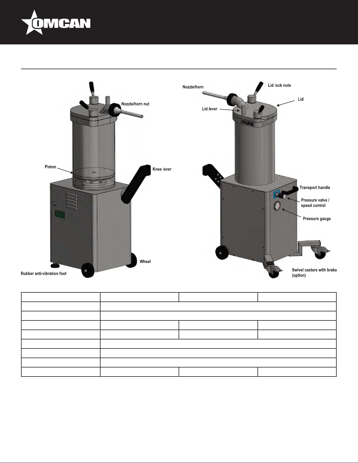
Sausage Stuffers
Models SS-ES-0026-F, 0026-FT, 0026-FS, 0048-FS, 0048-FT, 0048-F,
0065-F, 0065-FS, 0065-FT, 0095-F, 0095-FS, 0095-FT
Items 45950, 46099, 46098, 45920*, 45869*, 45959*, 45870, 46101*,
46100*, 45951, 46102, 46103*
Instruction Manual
Revised - 12/10/2018
Toll Free: 1-800-465-0234
Fax: 905-607-0234
Email: service@omcan.com
www.omcan.com
*
Page 2

Table of Contents
Model SS-ES-0026-F / Model SS-ES-0026-FT / Model SS-ES-0026-FS
Model SS-ES-0048-FS / Model SS-ES-0048-FT / Model SS-ES-0048-F
Model SS-ES-0065-F / Model SS-ES-0065-FS / Model SS-ES-0065-FT
Model SS-ES-0095-F / Model SS-ES-0095-FS / Model SS-ES-0095-FT
Section
General Information
Safety and Warranty
Technical Specications
Installation
Operation
Maintenance
Troubleshooting
-------------------------------------------------------------------------------------------------- 11 - 15
--------------------------------------------------------------------------------------------------- 15 - 17
----------------------------------------------------------------------------------------------- 18 - 23
----------------------------------------------------------------------------------------- 3 - 4
---------------------------------------------------------------------------------------- 4 - 8
------------------------------------------------------------------------------------------- 23 - 25
Page
---------------------------------------------------------------------------------- 9 - 10
Parts Breakdown
Electrical Schematics
Notes
Warranty Registration
-------------------------------------------------------------------------------------------------------- 44 - 46
----------------------------------------------------------------------------------------- 26 - 41
------------------------------------------------------------------------------------ 42 - 43
----------------------------------------------------------------------------------------- 47
2
Page 3

General Information
Omcan Manufacturing and Distributing Company Inc., Food Machinery of America, Inc. dba Omcan
and Omcan Inc. are not responsible for any harm or injury caused due to any person’s improper or
negligent use of this equipment. The product shall only be operated by someone over the age of 18, of
sound mind, and not under the inuence of any drugs or alcohol, who has been trained in the correct
operation of this machine, and is wearing authorized, proper safety clothing. Any modication to the
machine voids any warranty, and may cause harm to individuals using the machine or in the vicinity of
the machine while in operation.
CHECK PACKAGE UPON ARRIVAL
Upon receipt of an Omcan shipment please inspect for external damage. If no damage is evident on the
external packaging, open carton to ensure all ordered items are within the box, and there is no concealed
damage to the machine. If the package has suffered rough handling, bumps or damage (visible or concealed),
please note it on the bill of lading before accepting the delivery and contact Omcan within 24 hours, so we may
initiate a claim with the carrier. A detailed report on the extent of the damage caused to the machine must be
lled out within three days, from the delivery date shown in the shipping documents. Omcan has no recourse
for damaged products that were shipped collect or third party.
Before operating any equipment, always read and familiarize yourself with all operation and safety
instructions.
Omcan would like to thank you for purchasing this machine. It’s of the utmost importance to save
these instructions for future reference. Also save the original box and packaging for shipping the
equipment if servicing or returning of the machine is required.
---------------------------------------------------------------------------------------------------------------------------------------------------
Omcan Fabrication et distribution Companie Limité et Food Machinery d’Amerique, dba Omcan et
Omcan Inc. ne sont pas responsables de tout dommage ou blessure causé du fait que toute personne
ait utilisé cet équipement de façon irrégulière. Le produit ne doit être exploité que par quelqu’un de
plus de 18 ans, saine d’esprit, et pas sous l’inuence d’une drogue ou d’acohol, qui a été formé pour
utiliser cette machine correctement, et est vêtu de vêtements de sécurité approprié. Toute modication
de la machine annule toute garantie, et peut causer un préjudice à des personnes utilisant la machine
ou des personnes à proximité de la machine pendant son fonctionnement.
VÉRIFIEZ LE COLIS DÈS RÉCEPTION
Dès réception d’une expédition d’Omcan veuillez inspecter pour dommages externes. Si aucun dommage
n’est visible sur l’emballage externe, ouvrez le carton an de s’assurer que tous les éléments commandés
sont dans la boîte, et il n’y a aucun dommage dissimulé à la machine. Si le colis n’a subi aucune mauvaises
manipulations, de bosses ou de dommages (visible ou cachée), notez-le sur le bond de livraison avant
d’accepter la livraison et contactez Omcan dans les 24 heures qui suivent, pour que nous puissions engager
une réclamation auprès du transporteur. Un rapport détaillé sur l’étendue des dommages causés à la machine
doit être rempli dans un délai de trois jours, à compter de la date de livraison indiquée dans les documents
d’expédition. Omcan n’a aucun droit de recours pour les produits endommagés qui ont été expédiées ou cueilli
par un tiers transporteur.
3
Page 4

General Information
Avant d’utiliser n’importe quel équipement, toujours lire et vous familiariser avec toutes les opérations
et les consignes de sécurité.
Omcan voudrais vous remercier d’avoir choisi cette machine. Il est primordial de conserver ces
instructions pour une référence ultérieure. Également conservez la boîte originale et l’emballage pour
l’expédition de l’équipement si l’entretien ou le retour de la machine est nécessaire.
---------------------------------------------------------------------------------------------------------------------------------------------------
Omcan Empresa De Fabricacion Y Distribucion Inc. Y Maquinaria De Alimentos De America, Inc. dba
Omcan y Omcan Inc. no son responsables de ningun daño o perjuicío causado por cualquier persona
inadecuada o el uso descuidado de este equipo. El producto solo podra ser operado por una persona
mayor de 18 años, en su sano juicio y no bajo alguna inuencia de droga o alcohol, y que este ha sido
entrenado en el correcto funcionamiento de esta máquina, y ésta usando ropa apropiada y autorizada.
Cualquier modicación a la máquina anúla la garantía y puede causar daños a las personas usando la
máquina mientras esta en el funcionamiento.
REVISE EL PAQUETE A SU LLEGADA
Tras la recepcion de un envio Omcan favor inspeccionar daños externos. Si no hay daños evidentes en el
empaque exterior, Habra el carton para asegurararse que todos los articulos solicitados ésten dentro de la
caja y no encuentre daños ocultos en la máquina. Si el paquete ha sufrido un manejo de poco cuidado, golpes
o daños (visible o oculto) por favor anote en la factura antes de aceptar la entrega y contacte Omcan dentro
de las 24 horas, de modo que podamos iniciar una reclamación con la compañia. Un informe detallado sobre
los daños causados a la máquina debe ser llenado en el plazo de tres días, desde la fecha de entrega que se
muestra en los documentos de envío. Omcan no tiene ningun recurso por productos dañados que se enviaron
a recoger por terceros.
Antes de utilizar cualquier equipo, siempre lea y familiarizarse con todas las instrucciones de
funcionamiento y seguridad.
Omcan le gustaría darle las gracias por la compra de esta máquina. Es de la mayor importancia para
salvar estas instrucciones para futuras consultas. Además, guarda la caja original y el embalaje para el
envío del equipo si servicio técnico o devolución de la máquina que se requiere.
Safety and Warranty
DEFINITION OF WARNINGS AND SIGNAL WORDS
SAFETY WARNINGS AND SIGNAL WORDS USED IN THIS MANUAL
The safety instructions serve as indications and precautionary measures that must be taken into account or
adopted to avoid a dangerous situation.
This is the safety alert symbol. It is used to alert you to personal injury hazards. Obey all safety
4
Page 5

Safety and Warranty
messages that follow this symbol to avoid possible injury or death.
Warnings can be classied according to the severity of the hazardous situation. The classication is based on
an assumption of probability of being exposed to a dangerous situation and what could happen in such a case.
There are four kinds of warnings:
Indicates a hazardous situation which, if not avoided, will result in death or serious injury.
Indicates a hazardous situation which, if not avoided, could result in death or serious injury.
Indicates a hazardous situation which, if not avoided, may result in minor or moderate injury.
Is used to address practices not related to personal injury.
IMPORTANT INFORMATION:
NOTE: provides additional information to clarify or simplify a procedure.
SAFETY WARNINGS ATTACHED TO THE MACHINES
The safety symbols warn of special hazards and are placed in the relevant places on the machine. Check
warning symbols daily:
• Are all security symbols present?
• Are all safety symbols recognizable and readable?
Ensure that the safety plates / adhesives are rmly attached to the machine, are easily readable and are not
erased during the cleaning process. Disconnect the machine and secure the main switch against reconnection
if a warning symbol is missing or no longer recognizable. Do not reconnect the machine until they are in place
and all safety symbols are recognizable. If they become damaged or lost, contact your authorized dealer.
INTENDED USE OF THE MACHINE
In general, the hydraulic piston llers/stuffers are used to prepare sausages made of minced meat. Other
applications include dough or paste of any type that can ow through a nozzle/horn of Ø10mm. Never use
hard masses or pastes that do not ow and could cause dangerous overpressure. The temperature of the
dough to be stuffed should be higher than 2ºC (35ºF).Do not process frozen or semi-frozen doughs. Working
environment conditions: temperature +5 to + 40ºC (+40 to + 100ºF), relative humidity: 20 to 90%. The
maximum operating pressure must not exceed 120 bar.
Any other use would conict with the machine’s characteristics, the manufacturer is not liable for any damages
that may occur as a result of improper use.
5
Page 6

Safety and Warranty
MODIFICATIONS
DISCLAIMER OF LIABILITY
It is not allowed to modify the machine without the prior express authorization of Omcan, neither in its design
nor in its security systems. Omcan will not be liable for damages caused by arbitrary changes. When a user
makes essential modications to the machine, he assumes the manufacturer status. In such a case, he shall
be obliged to take all the measures incumbent on it legally as a manufacturer. The original manufacturer is
therefore released from its responsibility.
GENUINE PARTS
The machine is only allowed to be used with original Omcan accessories and spare parts. Omcan will not be
liable for damages caused by using tools, accessories or spare parts from other manufacturers.
IMPORTANT WARNINGS
Since the WARNINGS, CAUTIONS and INSTRUCTIONS in this manual cannot address all possible conditions
and situations that may arise, the operator MUST ALWAYS exercise common sense and due caution when
using this machine!
• DO NOT DISCARD THIS MANUAL; KEEP IT FOR FUTURE REFERENCE BY ALL USERS AND
MAINTENANCE PERSONNEL. PLEASE THOROUGHLY READ AND FULLY UNDERSTAND ALL THE
INSTRUCTIONS BEFORE SERVICING OR USING THE MACHINE.
• THIS MACHINE HAS MOVING PARTS AND USES VOLTAGES THAT ARE POTENTIALLY HAZARDOUS.
FAILURE TO FOLLOW THE INSTRUCTIONS CONTAINED IN THIS MANUAL COULD RESULT IN
SEVERE, POSSIBLY LIFE-THREATENING, PERSONAL INJURY.
• THIS MACHINE HAS BEEN DESIGNED EXCLUSIVELY FOR MEAT PROCESSING. USE OF THIS
MACHINE FOR ANYTHING OTHER THAN MEAT PROCESSING DOES NOT CONFORM TO ITS
INTENDED FUNCTION, IS STRICTLY PROHIBITED AND SHALL VOID Omcan’s WARRANTY. Omcan
ASSUMES NO RESPONSIBILITY FOR ANY DAMAGE OR INJURY RESULTING FROM IMPROPER USE
OF THIS MACHINE.
• DO NOT ALTER OR MODIFY THE MACHINE’S ORIGINAL DESIGN IN ANY WAY; DOING SO WILL VOID
Omcan’s WARRANTY AND MAY RESULT IN PERSONAL INJURY OR DAMAGE TO THE MACHINE.
• This machine MUST be installed ONLY by a qualied electrician in accordance with the instructions in this
manual and in compliance with all applicable national, regional and local electrical, safety and hygiene
standards and codes. Compliance with said standards and codes is the sole responsibility of the owner and
installer.
• DO NOT open the machine or tamper with its internal parts; none of the internal components requires
adjustment or maintenance by the user.
• DO NOT tamper with the machine’s mechanical or electrical safeguards.
• Use ONLY genuine Omcan parts or accessories and have them installed only by a qualied technician.
Use of unapproved parts and accessories voids Omcan’s warranty and may result in personal injury or
damage to the machine.
• NEVER attempt to repair the machine on your own. Should the machine require service, contact the
authorized dealer from whom you purchased the machine.
• Modications to the machine that raise noise emission levels above 85 dB(A) may result in hearing
6
Page 7

Safety and Warranty
damage. ALWAYS wear appropriate hearing protection.
OPERATING HAZARDS
• PLEASE READ THIS MANUAL CAREFULLY AND FULLY UNDERSTAND ALL THE INSTRUCTIONS
BEFORE USING THE MACHINE.
• DO NOT OPERATE THE MACHINE WITHOUT HAVING FIRST BEEN INSTRUCTED ON ITS USE,
MAINTENANCE AND SAFEGUARDS FROM AN EXPERIENCED OPERATOR.
• ALWAYS keep hands and hair away from moving parts when the machine is in use. There is the danger of
crushing hands, ngers, etc. when closing the lid or when the piston is raised while the lid is not completely
open.
• NEVER wear loose clothing or jewellery that could get caught on moving parts when the machine is in use.
• DO NOT use the machine without wearing the protective gear required by law.
• DO NOT leave the machine unattended while it is switched on or plugged to an electrical outlet. ALWAYS
unplug the machine when it is not in use.
• ALWAYS keep your work area well-lit and free of obstacles.
• ALWAYS keep children, visitors and bystanders away from the machine while it is in use or plugged to an
electrical outlet. NEVER allow children to operate the machine.
• SHOULD THE MACHINE MALFUNCTION, PROMPTLY TURN IT OFF AND NOTIFY THE APPROPRIATE
PERSONNEL.
• ALWAYS follow the hygiene and cleaning instructions in this manual and the local sanitary codes in order to
avoid contaminating the food mixture.
• ALWAYS rmly grip both the transport handle (located at the machine’s base) and the lid handle when
moving the machine. DO NOT tilt the machine too far while it is balanced on its wheels since it is heavy
and there is a risk of personal injury or property damage if it tips over.
ELECTRICAL HAZARDS
• DO NOT TAMPER WITH THE MACHINE’S ELECTRIC SYSTEM. THIS MACHINE MUST BE INSTALLED
ONLY BY A QUALIFIED ELECTRICIAN AND IN COMPLIANCE WITH APPLICABLE NATIONAL,
REGIONAL AND LOCAL ELECTRICAL CODES.
• ALWAYS USE CAUTION WHEN WORKING ON THE MACHINE’S ELECTRICAL SYSTEM SINCE THERE
IS A RISK OF ELECTRIC SHOCK DUE TO:
- DIRECT OR INDIRECT CONTACT WITH ELECTRIC CURRENT.
- IMPROPERLY INSTALLED DEFECTIVE OR DAMAGED ELECTRICAL PARTS.
• BEFORE operating the machine, make sure that all phases are connected properly and that the machine is
properly grounded and/or connected to a circuit leakage breaker and thermal switch. Failure to do so could
result in electric shock!
• DO NOT tamper with the machine’s electrical wiring or components after installation.
• ALWAYS disconnect the machine from the electrical outlet before proceeding with cleaning, maintenance,
or repairs.
• To avoid damaging the power cord and possible injury, keep it away from areas where it may be stepped
on or tripped over. DO NOT pull on the power cord to disconnect the plug from the electrical outlet; always
pull on the plug.
7
Page 8

Safety and Warranty
DISPOSAL
Risk of damage to people and environmental hazards. The machine is composed of different materials.
Observe local regulations on waste disposal. Instruct an authorized waste disposal company to dispose of
waste correctly.
1 YEAR PARTS AND LABOR WARRANTY
Within the warranty period, contact Omcan Inc. at 1-800-465-0234 to schedule an Omcan authorized
service technician to repair the equipment locally.
Unauthorized maintenance will void the warranty. Warranty covers electrical and part failures, not
improper use.
Please see https://omcan.com/disclaimer for complete info.
WARNING:
The packaging components are classied as normal solid urban waste and can therefore be disposed of
without difculty.
In any case, for suitable recycling, we suggest disposing of the products separately (differentiated
waste) according to the current norms.
DO NOT DISCARD ANY PACKAGING MATERIALS IN THE ENVIRONMENT!
8
Page 9
Technical Specications
14.2 L STUFFER
Model SS-ES-0026-F SS-ES-0026-FT SS-ES-0026-FS
Barrel Capacity 14.2 L / 3.7 Gal
Approx. Meat Capacity 26 lbs. / 11 kgs.
Power 1 HP / 0.75 kW 0.75 HP / 0.55 kW 1 HP / 0.75 kW
Electrical 110V / 60Hz / 1 208V / 60Hz / 3 220V / 60Hz / 1
Dimensions 19” x 21” x 49” / 483 x 533 x 1245mm
Weight 265 lbs. / 120 kgs.
Packaging Weight 310 lbs. / 140 kgs.
Item Number 45950 46099 46098
9
Page 10

Technical Specications
25.2 L STUFFER
Model SS-ES-0048-FS SS-ES-0048-FT SS-ES-0048-F
Barrel Capacity 25.2 L / 6.6 Gal
Approx. Meat Capacity 48 lbs. / 20 kgs.
Power 1.75 HP / 1.3 kW 1.5 HP / 1.1 kW 1.75 HP / 1.3 kW
Electrical 110V / 60Hz / 1 208V / 60Hz / 3 220V / 60Hz / 1
Dimensions 21” x 23” x 49” / 533 x 584 x 1245mm
Weight 310 lbs. / 140 kgs.
Packaging Weight 350 lbs. / 160 kgs.
Item Number 45920 45869 45959
35.1 L STUFFER
Model SS-ES-0065-F SS-ES-0065-FS SS-ES-0065-FT
Barrel Capacity 35.1 L / 9.2 Gal
Approx. Meat Capacity 65 lbs. / 28 kgs.
Power 1.75 HP / 1.3 kW 1.5 HP / 1.1 kW
Electrical 110V / 60Hz / 3 220V / 60Hz / 1 220V / 60Hz / 3
Dimensions 21” x 23” x 49” / 533 x 584 x 1245mm
Weight 350 lbs. / 160 kgs.
Packaging Weight 400 lbs. / 180 kgs.
Item Number 45870 46101 46100
51 L STUFFER
Model SS-ES-0095-F SS-ES-0095-FS SS-ES-0095-FT
Barrel Capacity 51 L / 13 Gal
Approx. Meat Capacity 95 lbs. / 40 kgs.
Power 2.5 HP / 1.87 kW 2.5 HP / 1.9 kW
Electrical 110V / 60Hz / 1 220V / 60Hz / 1 220V / 60Hz / 3
Dimensions 26” x 25” x 64” / 660 x 635 x 1626mm
Weight 580 lbs. / 260 kgs.
Packaging Weight 660 lbs. / 300 kgs.
Item Number 45951 46102 46103
10
Page 11
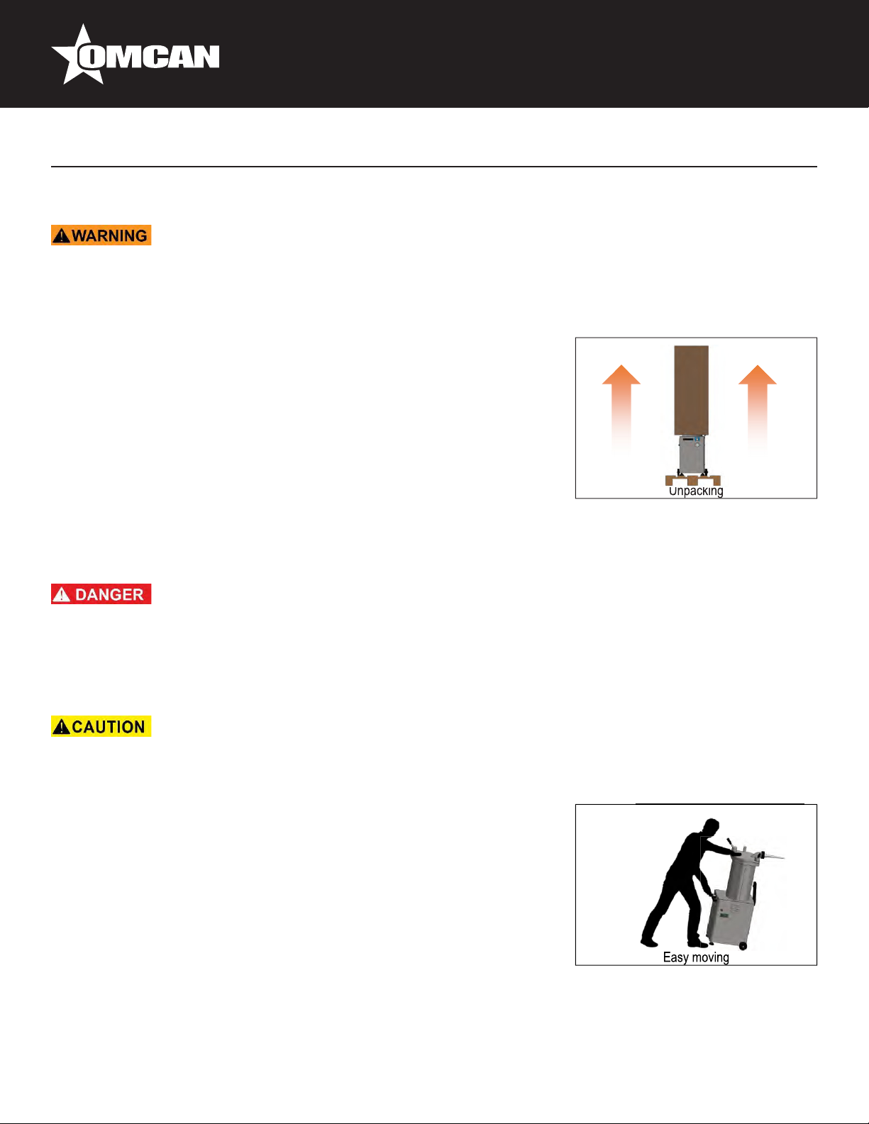
STORAGE, DELIVERY AND UNPACKING
• ALWAYS keep the machine upright, even while in its packaging.
• NEVER stack machines even if they are in their original packaging.
• NEVER place heavy objects on top of the machines or its packaging.
The machine is delivered on a pallet protected either by cardboard
packaging (F14/25/35) or wooden crate (F50). We use only recyclable
packaging and ask that you please recycle these materials.
Remove the packaging and thoroughly inspect the machine upon delivery.
Should you note any damage to the machine, retain all packing materials
and promptly notify the carrier. The transport company is solely responsible
for any damage to the machine during transit. If the machine is found to
be in satisfactory condition, follow the instructions in POSITIONING THE
MACHINE in order to safely convey it to a suitable work area. Your needs
will determine the most appropriate location for the machine.
Installation
PLACEMENT
ELECTRICAL HAZARD!
• The electrical installation of the enclosure must provide a thermal protection device (MCB) and leakage
(differential), conforming to the specications of each machine. A qualied electrician must adjust these
safety devices to the specications of your particular machine.
• Do not use the machine in wet locations.
• Do not lift the machine more than necessary, it could collapse.
• In order to move the F50 model, two people are required.
The machine should be placed in the most appropriate place, according
to the demands and needs of use. For a good, prolonged operation, the
machine should be placed in a sufciently ventilated area, avoiding lack
of air circulation. The workplace should be clean, free from obstacles and
have a horizontal and anti-slip surface. Observe a passage area around
the machine of 1 meter to proceed to use, clean and maintenance thereof.
To move the machine to the desired location:
• ALWAYS rmly hold the carrying handle and the lid handle to move the
machine. NEVER use the knee lever to move the machine!
• Tilt the machine so that it is balanced on its wheels and may be rolled
into place.
• ALWAYS place the machine on a at, level surface. Should the machine wobble, adjust the anti-vibration
legs until it is perfectly level and stable.
11
Page 12
Installation
• The machine should be positioned so that the power plug is easily accessible to the operator.
Do not store the machine in cold places (i.e. refrigerated storage house). Persistent low temperatures
can cause damages in the machine.
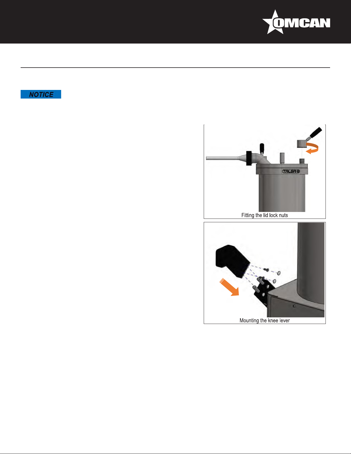
INSTALLATION OF THE LID LOCK NUTS AND
KNEE LEVER
Before using the stuffer it is necessary to assemble the lid lock
nuts and knee lever delivered with the machine.
• Screw the lid lock nuts on the threads projecting from the
lid. Do not overtighten, as this would hinder the opening and
closing of the lid.
• Place the knee lever at the anchor point.
• Attach the two screws with Allen wrench supplied with the
machine. Check the operation of the knee lever. It should
move with little effort and return to the center position when
released (in the lifting drive the piston).
• Place the two gray caps on the heads of the screws.
Knee lever position and action of the piston:
• When you push the toggle to the left, the piston must rise.
The knee lever automatically returns to the center position
when no pressure is applied thereon.
• When pushing the lever rightward the piston must descend.
In this position, the lever is automatically locked until
the piston reaches the lower position. The piston can be
stopped at any time by pushing the lever to the center
position.
It is possible to reverse the direction of drive knee lever / piston.
Consult your dealer where you purchased the stuffer.
12
Page 13
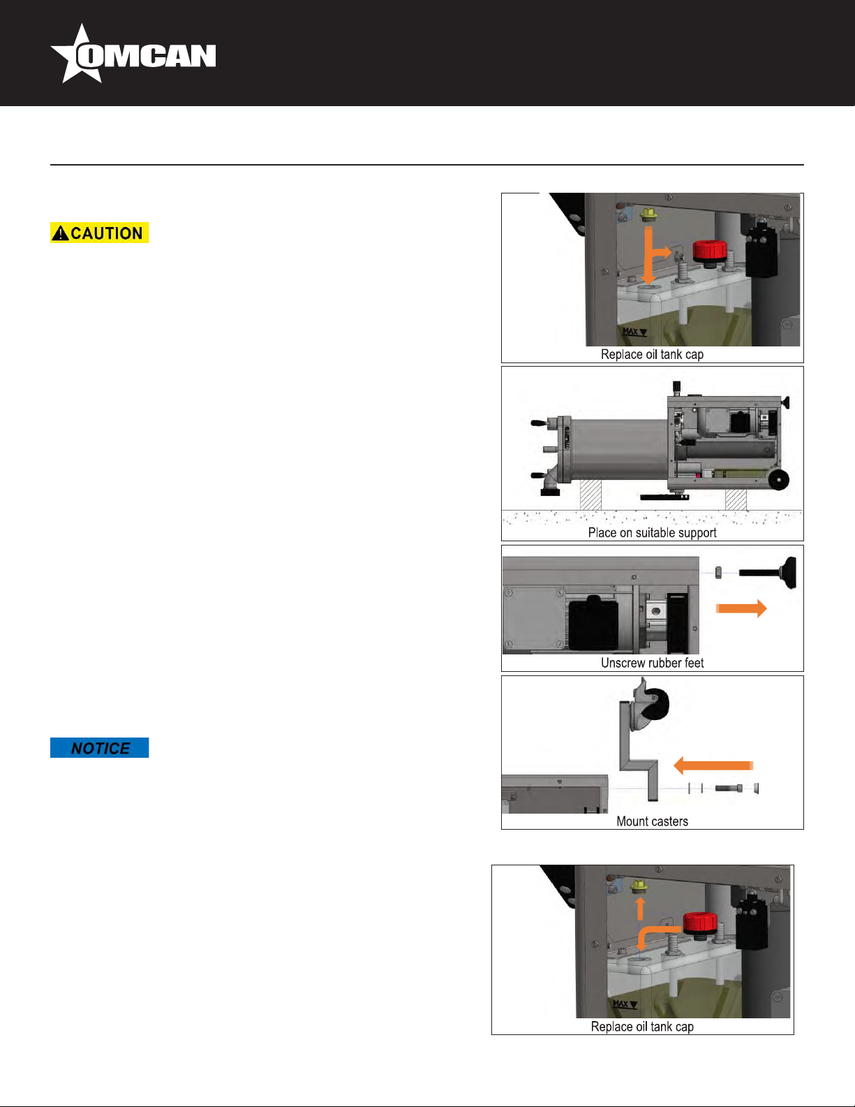
INSTALLING CASTERS (OPTIONAL)
• To lay down and lift the machine at least two people are
needed.
• ALWAYS secure the position of the machine setting the brakes
on the castors (optional).
Optionally the stuffer is provided with two pivoting wheels with
brakes that facilitate the movement of the stuffer. To install these
wheels follow the instructions below:
• Unscrew and remove the screws that hold the panel to the
machine base, then withdraw it.
• Remove the evaporator cap (red) and replace it with the
transport cap (yellow). This cap closes the oil reservoir
hermetically, avoiding leakage of hydraulic oil for the following
steps.
• Lay the machine to the side of the knee lever, on a suitable
support to prevent damaging the lever. To lay down and lift the
machine at least two people are needed.
• Remove the anti-vibratory rubber feet unscrewing them from
the machine body.
• Attach the extensions and casters with the screw and washers
provided.
• Lift the machine (at least two people are required).
• Very important! Before operating the machine, replace the
evaporator cap (red) in the oil tank.
• Check the operation of the machine and close machine body
cover.
Installation
Before putting the machine into operation, make sure to
replace the transport cap (yellow) with the cap of the oil tank
(red). Operating the machine with the yellow transport cap
will damage the hydraulic system!
TRANSPORT CAP OF THE OIL TANK (MACHINES
SENT LYING)
Machines sent lying on a pallet (air shipment), have a transport
oil cap (yellow) closing the oil tank hermetically, to prevent
oil leakage during transport. Before operating the machine,
replace the transport oil cap by the depressurized oil cap (red)
delivered with the machine.
• Unscrew and remove the screws that hold the panel to the
13
Page 14

Installation
machine base, then withdraw it.
• On the oil reservoir, replace the transport oil cap (yellow) by the depressurized oil cap (red).
• Check the oil level in the tank. It must be between the MAX and MIN marks on the tank. If necessary, add
enough oil to bring the level up to the maximum mark. Do not ll the tank completely, as a certain volume of
air for expansion of the oil is necessary.
• Replace the panel at the end of operations.
• Before putting the machine into operation, make sure to replace the transport cap (yellow) with the cap of
the oil tank (red). Operating the machine with the yellow transport cap will damage the hydraulic system!
• The llers are supplied from factory with the appropriate hydraulic oil level. Therefore, it is usually not
necessary to rell it. In the exceptional event that the new machine is delivered with a lack of hydraulic oil,
DO NOT connect it. Proceed to ll it before operation.
CONNECTING TO THE POWER SOURCE
ELECTRICAL HAZARD!
• This machine must be installed only by a qualied technician and in compliance with applicable national,
regional and local electrical codes.
• The machine MUST remain disconnected from the power supply throughout this procedure.
CHECK THE WIRING BEFORE CONNECTING THE MACHINE! Call a qualied electrician if the electrical
specications do not correspond with your power source: the wiring in the electrical cord is normally assigned
as follows: PHASE(S): Black, Brown or Gray. NEUTRAL: Blue (or White in some non CE/CEN/UE countries).
GROUND: Bi-coloured Yellow / Green (or Green in some non CE/CEN/UE countries).
• Ensure that the electrical characteristics of the stuffer, detailed in the plate xed to the machine (voltage,
frequency, Hz, phases), coincide with those of the mains. A tolerance of ± 10% in voltage and frequency ±
2% is accepted.
• If they match those of the network, have a qualied electrician connect a plug to the power cord.
• If the voltage of the machine does not match the network, and if dual voltage three-phase motor, it
appropriate to adjust the voltage thereof, as described in Voltage change and then have a qualied
electrician connect a plug to the power cord.
• It is mandatory the use of a standard plug for connecting the machine.
Once connected machine check the proper operation of the stuffer: push the brace rmly to the left (rising
piston).
• If the phases are correctly connected, the piston will rise and lower correctly when operating the knee lever.
• If the phases are not well connected, the pump will operate in reverse, the motor will make noise but
the piston will not move. Stop the machine immediately and switch it from the mains. Have a qualied
technician permute two of the three phases in the plug; NEVER inside the machine.
14
Page 15
VOLTAGE CHANGE
ELECTRICAL HAZARD!
• This operation must only be carried out by a qualied electrician!
• The machine MUST remain disconnected from the power supply
throughout this procedure.
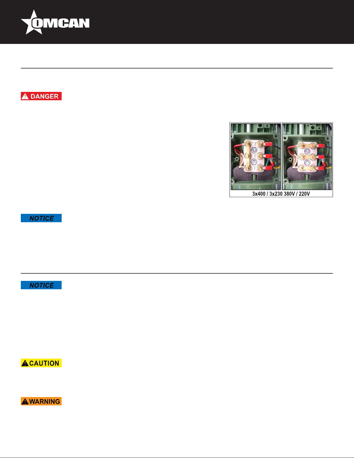
Only dual voltage three-phase machines powered 380 / 220V (400 /
230V EU) Unscrew and remove the screws that hold the panel to the
machine base, then withdraw it. Make the following changes in the
components:
• Open the terminal box by removing the screws 4 thereof.
• Release 6 locknuts small terminals.
• Put the plates in the correct position.
• Reseal the motor terminal box.
• Replace the panel at the end of operations.
Installation
The Qualied electrician in charge of changing the voltage of the machine should refer to the corresponding
wiring diagrams in this manual.
Operation
• BEFORE STARTING WORK, PLEASE READ AND UNDERSTAND THIS ENTIRE MANUAL AND SAFETY.
• DO NOT use the machine without having been instructed by an advanced user.
• Practice using the machine in vacuum before contacting mass.
• This machine is not designed to run in continuous operation uninterrupted at high pressures, but
intermittent operation stops dissipating the heat generated varies depending on the consistency of the
product.
STEPS TO FOLLOW
• If the phases are not well connected, power up the pump will operate in reverse, the engine make noise but
will not move the piston. In this case stop immediately and disconnect the machine from the mains.
• Have a qualied electrician permute two of the three phases in the plug.
• Observe all hygiene measures in food processing, using the necessary protection material (washing,
gloves, hat, apron, etc.)
15
Page 16

Operation
1. Fully open the lid. Reduce friction by unscrewing the lid locking nuts.
2. Before the rst use, and regularly thereafter, wash the tank, lid and
nozzles/horns with hot water.
3. Decrease working pressure of the machine to minimum, by turning
the pressure valve knob to the left (counter-clockwise).
4. Plug the machine to the mains.
5. Lower the piston pushing the knee lever to the right up to the
required volume to accommodate the desired meat mass.
6. Place meat dough in the tank while pressing each load to prevent
the presence of air pockets that can break the casing in the working
process.
7. Place the lid seal in its housing with the lip upwards. The lid seal has
a unique position with the protruding lip upwards.
Remember: Do not close the lid without the gasket or mounted
backwards, because doing so would harm the gasket or lid.
8. Raise the piston using the knee lever until the mass reaches the top
of the tank.
9. Lubricate with edible fat, or other USDA approved for food, the top of
the lid seal and the bottom of the lid.
10. Close the lid gently. Be careful not to pinch your hand in the closing
process.
Important: Do not use the nozzle/horn to close the cover, as
it could be twisted; exclusively use the lever for opening and
closing lid.
Tighten the lid lock nuts close enough so the pressure cannot raise
the lid.
11. Attach the appropriate nozzle/horn (as wide and short as possible) to
the nozzle/horn holder on the lid, securing it with the nozzle/horn nut.
12. Prepare enough casings.
13. Press the leg against the knee lever up to its limit. It is not
recommended to use the knee lever only halfway as an accelerator,
always push it until its limit.
14. Cautiously increase the working pressure by slowly rotating pressure
valve knob clockwise (in the direction of clock). Avoid high pressure,
as it may be excessive and the meat would practically spurt out of the
nozzle/horn.
15. When meat mass starts to gush out of the nozzle/horn, reduce the
pressure and place the casings. Adjust the pressure to the ideal
speed.
Remember: The air trapped between the meat mass and the lid
will be expelled rst through the nozzle/horn before the mass begins to ow.
16. Once the work is nished, push the knee lever to the right. It is not necessary to keep pushing the lever,
since the machine has an automatic lock until the piston reaches the lower position. To stop the hydraulic
unit at any time, leave the knee lever at the center position.
16
Page 17

Operation
17. When nished using the machine, proceed to clean it thoroughly.
Always turn down the piston to the bottom of the tank, disconnect the
electric plug from the base and make sure the machine’s brakes are
tightened, thus avoiding any involuntary displacement in your absence.
Remember: clean the ller according to the instructions on the
cleaning section when nished using the machine at the end of
the day.
• DO NOT leave the machine unattended while it is powered on or in operation.
• ALWAYS rmly grip both the transport handle (located at the machine’s base) and the lid handle when
moving the machine. DO NOT tilt the machine too far while it is balanced on its wheels since it is heavy
and there is a risk of personal injury or property damage if it tips over).
• ALWAYS keep hands away from any moving parts while the machine is in operation. There is the danger of
crushing hands, ngers, etc. when closing the lid or when the piston is raised while the lid is not completely
open.
• To prevent mechanical hazards and personal injury, do not open or close the cover if the machine is
operating.
• Be careful when removing the lid. Because of its weight it could fall and cause injury.
USEFUL TIPS
• The minimum operating temperature for the ller is 5°C. Therefore never store the machine in cold rooms,
freezers, etc.
• This machine is not designed to operate in continuous uninterrupted service, but to work on an intermittent
regime with stops to dissipate the heat generated which varies depending on product consistency.
• Given the pressure transmitted to pump hydraulic oil, it is normal that the temperature can raise above
60°C and the machine body is hot after a prolonged operating period.
• For a better presentation of the sausage lling process, smoother and less effort and heating of the
machine the following is recommend:
- Select nozzle/horn with the largest diameter and shortest length possible.
- Meat mass should be minced/chopped as ne as possible and as warm as possible.
• During operation of the machine with dough, you cannot open the lid until lowering the piston a bit, since
the compressed meat mass would prevent it.
• Approach the ller to the worktable as much as possible to avoid meat falling to the ground or on the
operator.
• Try to work at a reasonable speed and pressure, thus avoiding constant starts and stops the hydraulic unit.
17
Page 18

Maintenance
CLEANING INSTRUCTIONS
• If using detergents, disinfectants or oils maintenance, observe the special instructions of the
manufacturers.
• NEVER use water pressure jet to clean or rinse any part of the machine.
• NO use abrasive products, especially those erasable plates or safety adhesives.
• NO open or close the lid without the red seal, because doing so will scratch the cover and ange.
• To prevent mechanical hazards during cleaning operations and removing the piston, always open the lid
completely before making up the piston.
Electrical Hazard!
• The machine MUST remain disconnected from the power supply throughout the entire cleaning procedure.
• NEVER wet or dampen the machine’s electrical components (switches, cables, etc.)
• To proceed with the manual cleaning using suitable protection (latex gloves, plastic apron, etc.) is required.
• ALWAYS necessary intensive rinsing machine after application of detergents or disinfectants to prevent
contamination of the mass.
Cleaning the ller is essential not only for health reasons but also for efcient operation. NEGLIGENCE IN
CLEANING MAY VOID THE WARRANTY. Stuffer should be cleaned after and, where appropriate, before each
use. To facilitate this, Omcan has designed these machines so that all components are easily accessible.
EXTERIOR CLEANING
• To clean the exterior of the machine use hot water and a mild
detergent.
• After each day the bottom of the lid (mass outlet hole), the nozzle/horn
holder nut and the nozzles/horns must be thoroughly cleaned, inside
with a tubular round brush.
• Use plenty of hot water to clarify the axis of rotation of the lid in order to
remove residual salt and spices that might crystallize and swell after a
few hours / days of inactivity and prevent the lid is opened and closed
easily.
• The top of the piston silicone gasket should also be cleaned daily by
following these steps:
- Fully open the lid and remove the lid gasket.
- Press the knee lever until the piston reaches the top of its travel. A
portion of the piston silicone gasket will hover at the top of the tank.
- Clean with a soft brush and / or damp cloth.
• The lid and piston of the ller are heavy as they are made of solid stainless steel. Be careful when
removing them.
18
Page 19

Maintenance
• Due to their heavy weight, it is recommended to remove the lid and piston of the F50s between two people.
INTERIOR CLEANING
It is recommended to periodically clean the inside of piston and tank. The
frequency depends on the product (dough consistency), working pressure,
etc. We recommend starting with a daily inspection, lengthening intervals
depending on their needs.
• Fully open the lid and remove the gasket.
• Press the knee until the piston reaches the top of its travel.
• The piston being at the top and simultaneously pushing the knee lever,
unscrew the screw located in the center of the piston with the aid of the
extractor key supplied with the machine.
• Press the knee lever so that the piston goes down a little.
• Screw the extractor key into the thread of the piston, then press the knee
lever to raise the piston.
• Pull up the key to take the piston out of the machine.
• Disconnect the machine.
• Proceed to clean the tank, perfectly drying the bottom in order to avoid
the formation of water pockets and subsequent oxidation of the top
of the machine body. The hole at the bottom of the tank is a for water
drainage.
• Clean the piston and silicone gasket.
• To prevent noise on the rise or lowering of the piston, lubricate the piston
silicone gasket before inserting it into the reservoir, with edible fat or
other authorized USDA food.
• To mount the piston:
- Perfectly dry the bottom of the tank.
- Place the piston in the reservoir and fully tighten the piston screw,
taking care that the small seal is installed correctly.
- Then raise and lower the piston and then tighten the screw to ensure
that it is secure. Otherwise it could bend when pushed against the lid.
- Lubricate the piston screw and thread before placing it. This will make
disassembly easier.
• When the machine is not in use, keep the piston at the bottom of the tank. Being immersed in the hydraulic
oil will prolong the life of the rod and seals.
GENERAL CLEANING RECOMMENDATIONS
Steps Products Tools Observations
Supercial cleaning & residue
removal.
Extensive cleaning. Mild
detergent.
Spatula. Promptly after use.
Brush,
bucket.
19
Allow the product to work approximately 15
minutes.
Page 20

Maintenance
Rinsing. Warm water. Sponge,
bucket.
Inspection. Visually examine all critical components,
Disinfecting. Disinfectants;
NEVER use
bleach.
Rinsing. Potable
water.
Drying. Cleaning
Conservation. Lubricating
oil.
Sponge,
cleaning
cloth.
Sponge,
bucket.
cloth.
Cleaning
cloth.
The water should be 40 to 50°C (100 to
120°F).
especially those subject to stress and wear.
Disinfect after completing all other cleaning
operations.
ALWAYS rinse the machine thoroughly after
using detergents and disinfectants.
Be sure to completely dry all cleaned
components.
Only external machine parts.
RECOMMENDED CLEANING INTERVALS
Interval Area to be cleaned Product Tools Observations
Daily. Daily Lid, lid gasket,
tank and piston
screw.
Weekly. Piston, piston seals
and piston screw
gasket
Every two
weeks.
NOTE: The above cleaning intervals are suggested for companies with just one work shift. The
machine should be cleaned more frequently if it is used for multiple shifts each day.
Machine body, bottom
of the machine.
Mild detergent, warm
water.
Mild detergent, warm
water.
Mild detergent, warm
water.
Sponge,
cleaning
cloth.
Sponge,
cleaning
cloth.
Sponge,
cleaning
cloth.
Mild detergent, warm water
Sponge, cleaning cloth
Remove contamination from
the piston center screw
using, if necessary, a brush to
prevent the accumulation of
waste.
To remove the piston follow
the instructions detailed
above.
STAINLESS STEEL CARE
Never use aggressive cleaners with stainless steel such as bleach or similar chlorine derivatives products. If
you have used it, never leave acting, rinse immediately with plenty of water and dry thoroughly.
It is uncommon, but possible, that small traces of rust or oxidation points may be observed on the machine.
This may be due to:
• Welding impurities.
• Food fragments adhering to the surface.
20
Page 21

Maintenance
• Pits resulting from use of aggressive cleaners such as bleach or similar chlorine derivatives products.
• Moisture that remains after cleaning with water. ALWAYS wipe dry all components that have been cleaned.
To remove these rust spots simply use a liquid stripper with a cloth, or clean with Scotch Brite.
MAINTENANCE
• ALWAYS unplug the machine before proceeding with maintenance and inspection.
• ALWAYS follow the safety instructions in this manual during maintenance and inspection operations.
Breakdowns resulting from infrequent or improper maintenance can lead to expensive repairs, lost productivity
due to down time and could void our warranty; therefore, regular and adequate maintenance is indispensable.
The safety and life of the machine depend on many factors, including proper maintenance. Although it is
difcult to give specic advice regarding inspection, maintenance or parts replacement schedules since these
depend on many variables related to the machine’s use, we can make some recommendations. The user,
however, is solely responsible for formulating and following an inspection and maintenance schedules that
reect the machine’s actual use. Our local distributor will be delighted to provide you with further information.
MAINTENANCE AND INSPECTION INTERVALS
Inspection interval Critical component Maintenance information
Daily. Lid gasket. Check it and replace it if necessary.
Piston silicone seal. Check it and replace it if necessary.
Monthly. Knee lever. Performance review and grease if necessary.
Lid opening. Performance review and grease if necessary.
Annually. Hydraulic oil. Check the level and ll the reservoir if neces-
sary.
Every 2,500 to 5,000 hours. Hydraulic oil. Change the hydraulic oil.
The above maintenance and inspection intervals are suggested for a machine under normal use. The ller
should be inspected and maintained more frequently if it is used heavily.
MAINTENANCE AND INSPECTION TIPS
Electrical Hazard!
• If the electric cord becomes damaged, immediately have a qualied electrician replace it with a cord of
identical specications. Contact your dealer’s service department to obtain the replacement cord.
• Lid gasket:
- Replace in case of leakage of meat dough, in case of wear or breakage.
- To reduce friction between the gasket and the bottom of the lid, lubricate both with animal or authorized
21
Page 22

Maintenance
fat.
- It is manufactured of non-toxic material suitable for food use.
• Piston seal:
- Replace if leakage or breakage.
- To avoid noise when raising or lowering the piston, lubricate before inserting the piston into the tank with
edible fat or other food authorized USDA
• Hydraulic: to avoid premature wear of the rod of the hydraulic reservoir, keep the piston at the bottom of the
tank when nished using the machine. This way the rod will remain submerged in hydraulic oil.
• Lid closing: the lid can be closed more or less tightening the lid locking nuts, depending on the degree of
sealing to be obtained. If you normally work with dry meat masses you can tighten the nuts with less force;
for liquid masses you may close the lid more tightly and thus avoid the possibility of leakage.
• Spare parts: if you need a spare, contact your dealer who sold the unit, indicating all identication details
(model, serial number, year of manufacture, power, voltage, frequency, etc.) you’ll nd on the nameplate of
the machine.
HYDRAULIC OIL
• Hydraulic oil level:
- Check the oil level on the marks of the tank. Unscrew and remove
the screws that hold the panel to the machine base, then withdraw it.
- On the tank, check that the oil level is between the MAX and MIN
marks.
- Fill the tank to the maximum level (not over), since the greater
amount of cooling oil will improve dissipation of heat from the
hydraulic unit, increasing its useful life.
- The lack of oil for operation can be noticed if the piston rises
“leapfrog” to allow air to enter the circuit.
• Oil temperature: given the pressure transmitted to pump hydraulic oil,
it is normal that the temperature can rise up to 60° C and the machine
body becomes hot after prolonged operating period. This machine
is not designed to run in continuous, uninterrupted operation at high
pressures, but to work in an intermittent regime with stops to dissipate generated heat.
• Hydraulic oil life: Omcan cannot provide accurate data on the life of the oil, because it depends on several
variable factors: temperature, operating pressure, presence of moisture or traces of water, etc. It can be
estimated at 5,000 hours, depending on conditions. If the oil thins, is dirty and shows presence of impurities
or after using the machine has a whitish color due to the presence of water, replace it by rst emptying the
oil deposit. Fill in oil following the instructions. Normally the hydraulic oil level will be maintained for years.
• Replacing the hydraulic oil:
- It is recommended to remove used oil with a suction pump oil.
- Unscrew and remove the screws that hold the panel to the machine base, then withdraw it.
- Remove the depressurized oil cap (red) and enter the suction pipe of the pump through the same hole.
Ensure that the tubing reaches the bottom of the tank to suck any impurities. Empty the tank by pumping
the oil in a suitable container. Please recycle used oil.
- Using a funnel or lling gun, enter the amount of hydraulic oil indicated in the table, through the lling
hole. Do not ll the tank completely, as a certain volume of air is required for expansion of the warm oil.
22
Page 23

Maintenance
- Move the piston up and down two or three times in order to purge and remove air pockets circuit. The lack
of enough oil for operation can be seen that the piston rises “leapfrog” to allow air to enter the circuit.
- If an oil suction pump is not available, the oil reservoir can be disassembled by releasing the oil reservoir
tubes and screws. Remove the tank and pour the oil through the lling hole into a suitable container.
Model Oil reservoir capacity
F14 6 liters / 1.6 US Gal
F25 & F35 7 liters / 1.9 US Gal
F50 13 liters / 3.4 US Gal
Use high pressure hydraulic oil (200 bar) ISO VG 46 viscosity and quality level equivalent to ISO 67434: 2015 DIN 51524-2 or HM: 2006-04 HLP.
Troubleshooting
• ALWAYS power off and unplug the machine from the electrical outlet before proceeding with cleaning,
maintenance, or repairs.
• If you are unable to resolve the difculty, DO NOT CONTINUE TO USE THE MACHINE and contact your
authorized Omcan dealer for service.
Problems Possible Causes Solutions
The machine is not working. The machine is switched off. Connect the machine.
The sound of the motor rotation is
heard, but the piston does not go
up or down when pushing the knee
lever.
The machine is connected to a
lower voltage.
Without tension in one or more
stages.
The internal micro switch on / off
the knee lever is defective or not
properly adjusted.
The pressure valve is at the
minimum.
The motor turns in the opposite
direction to the correct.
Change the voltage of the machine
to the right.
Check fuses, plugs and switches.
Contact an electrician to replace or
readjusted.
Increase pressure by turning knob
clockwise.
Permute two of the three phases in
the plug.
23
Page 24

Troubleshooting
The piston moves up and down
but the machine seems to lack
strength.
The air passage hole located at the
base of the tank is clogged.
The piston and the piston seal are
dirty.
The mains voltage is not
compatible with the selected for
the engine.
The three-phase motor (if
applicable) is only running two
phases.
There is little hydraulic oil. Fill the oil reservoir up to “MAX”
There is an oil leak in the ttings or
pipes.
The chambers of the hydraulic
cylinder are communicated.
REFERENCE
Item Number Model Number Description
45950 SS-ES-0026-F
46099 SS-ES-0026-FT
46098 SS-ES-0026-FS
45920 SS-ES-0048-FS
45869 SS-ES-0048-FT
45959 SS-ES-0048-F
45870 SS-ES-0065-F
46101 SS-ES-0065-FS
Sausage Stuffer 26 LB/12 KG Capacity Stainless
Steel Hydraulic Piston 1HP/0.75kW 110V/60/1
Sausage Stuffer 26 LB/12 KG Capacity Stainless
Steel Hydraulic Piston 0.75HP/0.55kW 208V/60/3
Sausage Stuffer 26 LB/12 KG Capacity Stainless
Steel Hydraulic Piston 1HP/0.75kW 220V/60/1
Sausage Stuffer 48 LB/22 KG Stainless Steel
Hydraulic Piston 1.75HP/1.3kW 110V/60/1
cQPSus
Sausage Stuffer 48 LB/22 KG Capacity
Stainless Steel Hydraulic Piston 1.5 HP/1.1kW
208V/60HZ/3PH cQPSus
Sausage Stuffer 48 LB/22 KG Capacity Stainless
Steel Hydraulic Piston 1.75 HP/1.3kW 220V/60/1
cQPSus
Sausage Stuffer 65 LB/29 KG Capacity Stainless
Steel Hydraulic Piston 1.75HP/1.3kW 110V/60/1
Sausage Stuffer 65 LB/29 KG Capacity Stainless
Steel Hydraulic Piston 1.75HP/1.3kW 220V/60/1
cQPSus
Clean it.
Clean them.
Contact an electrician to change
the voltage of the machine.
Contact an electrician to check
electric grid.
Call your local dealer.
Call your local dealer.
Manufacturer Model
Number
F14s/26 110/60/1
F14s/26 208/60/3
F14s/26 220/60/1
F25s/48 110/60/1
F25s/48 208/60/3
F25s/48 220/60/1
F35s/65 110/60/1
F35s/65 220/60/1
24
Page 25

46100 SS-ES-0065-FT
45951 SS-ES-0095-F
46102 SS-ES-0095-FS
46103 SS-ES-0095-FT
Troubleshooting
Sausage Stuffer 65 LB/29 KG Capacity Stainless
Steel Hydraulic Piston 1.5HP/1.1kW 208-
220V/60/3 cQPSus
Sausage Stuffer 95 LB/43 KG Capacity Stainless
Steel Hydraulic Piston 2.5HP/1.87kW 110V/60/1
Sausage Stuffer 95 LB/43 KG Capacity Stainless
Steel Hydraulic Piston 2.5HP/1.87kW 220V/60/1
Sausage Stuffer 95 LB/43 KG Capacity Stainless
Steel Hydraulic Piston 2.5HP/1.87kW 208-
220V/60/3 cQPSus
F35s/65 220/60/3
F50s/95 110/60/1
F50s/95 220/60/1
F50s/95 220/60/3
25
Page 26

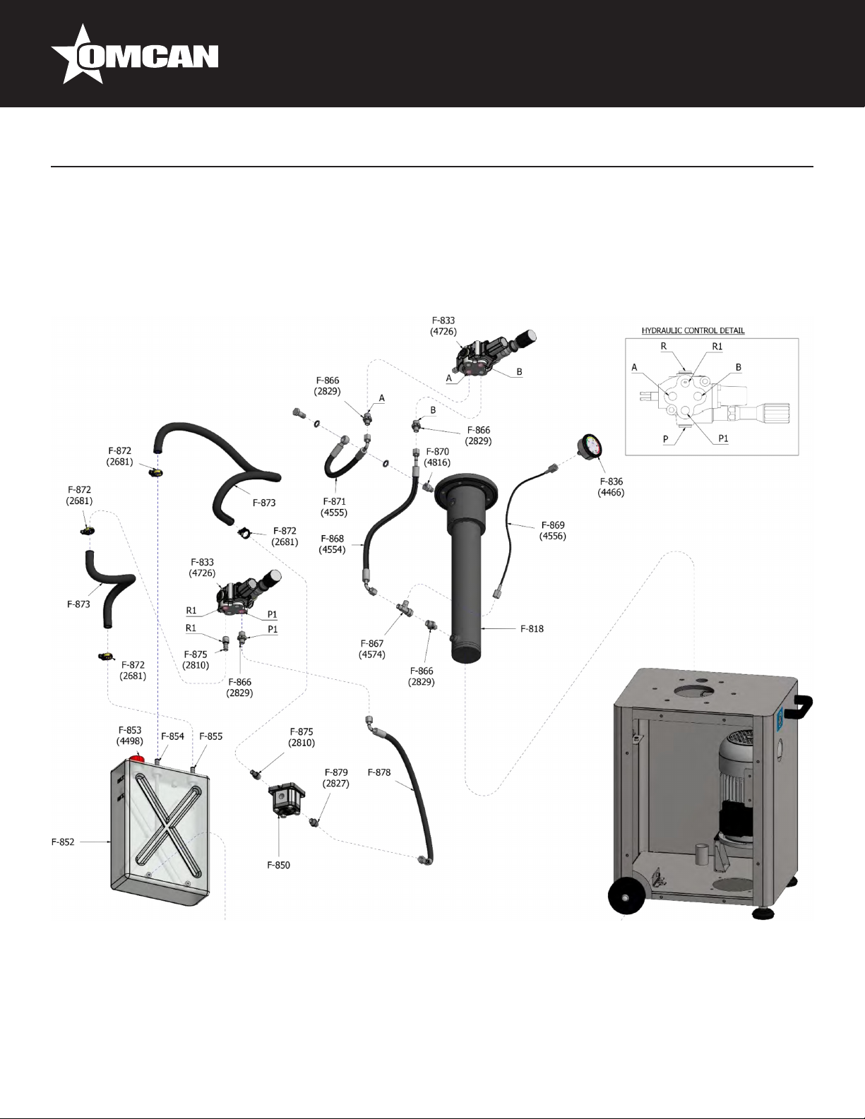
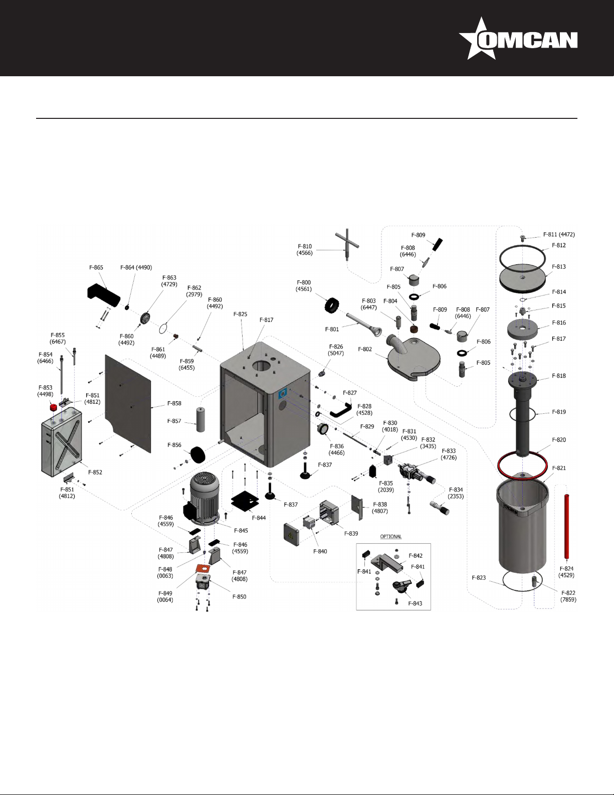
Parts Breakdown
Model SS-ES-0026-F 45950
Model SS-ES-0026-FT 46099
Model SS-ES-0026-FS 46098
26
Page 27
Model SS-ES-0026-F 45950
Model SS-ES-0026-FT 46099
Model SS-ES-0026-FS 46098
Parts Breakdown
27
Page 28

Parts Breakdown
Model SS-ES-0026-F 45950
Model SS-ES-0026-FT 46099
Model SS-ES-0026-FS 46098
Item No. Description Position Item No. Description Position Item No. Description Position
66842
66843
66844
66845
66846
66847
66848
66849
66850
66851 Nut for Lid Lock AISI303 for F14S F-807 66874
66852
66853 Knob Black Thread M10 80mm for F14S F-809 66876
66854
66855
66856
66857
66858
66859
66860
66861
66862
66863
66864
Nozzle/Horn Retention Nut Black for
F14S
Nozzle/Horn Poliet. HD Translucent
D.Ext.14 Int.10L.Use 160mm (6") for
F14S
Nozzle/Horn Poliet. HD Translucent
D.Ext.20 Int.16L.Use 196mm (8") for
F14S
Nozzle/Horn Poliet. HD Translucent
D.Ext.30 Int.26L.Use 196mm (8") for
F14S
Stainless Steel Lid, without Accessories
for F14S
Lid Opening Lever AISI303 (All Stuffers/
Fillers FS) for F14S
Bras Bushing B11 A-42-54-30 Lid for
F14S
Stainless Steel Bolt, M39/M36 Lid for
F14S
Bushing for Lid Lock Nut, Plastic APM500
Black for F14S
Lever for Lid Lock Nut AISI303, without
Black Knob for F14S
Spanner/Wrench, Piston Extractor for
F14S
CSK Allen Screw, Stainless Steel
M16x35 DIN7991 for F14S
O-Ring, Int. Diam. 345x10 Red Silicone
(1*Piston) for F14S
Piston, Stainless Steel, without O-Ring
for F14S
O-Ring, Int. Diam. 34x2mm Threaded Tip
Piston for F14S
Threaded Tip Hydraulic Cylinder Bolt
AISI303 for F14S
Hood Clamp, Hydraulic Cylinder,
D.198mm NBR70 for F14S
Stainless Steel Hexagonal Screw,
M12x35 DIN933 for F14S
Hydraulic Cylinder, DE0450800449G01
Filler/Stuffer for F14S
O-Ring, Int. Diam. 165x5mm, Hydraulic
Cylinder for F14S
Lid Seal Polyurethane Red, Diam.Ext.
404mm for F14S
F-800 66865 Fixed Dough Barrel for F14S F-821 66881
F-801 66866
F-801 66867
F-801 66868
F-802 66869 Cabinet with Accessories for F14S F-825 39059 Air Extraction Fan 220V 1PH for F14S F-844
F-803 66870
F-804 66871 Handle M8 for F14S F-827 36045
F-805 66872
F-806 66873
F-808 66875
F-810 66877
F-811 31219
F-812 16524
F-813 66878
F-814 66879 Foot, Stainless Steel for F14S F-837 66892 Oil Return Pipe D.10 L.120mm for F14S F-854
F-815 66880 Holder Isolating Box for F14S F-838 66893 Oil Suction Pipe D.10 L.270mm for F14S F-855
F-816 36042
F-817 66048
F-818 79579
F-819 44094 Contactor 6A 220V/60Hz/1 for F14S F-840 66896 Brass Bushing, B11 A-6-9-12 for F14S F-860
F-820 44093 Contactor 6A 208V/60Hz/3 for F14S F-840 66897
Deposit Drainage Pipe D.27 L.62 Gas
3/4" AISI304 for F14S
O-Ring, Int. Diam. 340x4, Flange Dough
Barrel for F14S
Transparent Fabric Hose PVC D.32x25,
Deposit Drain for F14S
Grommet, S-Tec 5308959 M20x1,5/13
Poliamyde, Grey for F14S
Wall Pass-Through D.34/21,8x6mm
EPDM Black 70 SH for F14S
Threaded Rod Hydraulic Control M8
L=268mm AISI304 for F14S
Internal Fork, Hydraulic Control Activator,
Stainless Steel for F14S
Cylindrical Pin, D.6x19,5 Stainless Steel
for F14S
Holder, Microswitch Distributor, Stainless
Steel for F14S
Hydraulic Control 102N8SA23X-340 with
Pressure Knob for F14S
External Pressure Valve Control Assembly M1670/861, Black Knob for F14S
Micro Position Deterctor, Comepi Metal
Wheel for F14S
Pressure Gauge D.63, WIKA 213.53,
0-200 Bar, Thread 1-4" for F14S
Isolating Box, Legrand 100x100x55mm
Code 92138 for F14S
Isolating Box, IDE 162x116x76, Polycarbonate (H UL-CSA +110V) for F14S
Contactor, LS MC-22B AC 110V/60&50Hz
1A1B EXP A.C. 22 AMP for F14S
F-822 66882
F-823 66883
F-824 66884 Fan, 110V-60HZ-1 for F14S F-844
F-826 66885 Motor, 110V-60HZ-1 for F14S F-845
F-828 36048
F-829 66886
F-830 66887 Support Motor Cabinet for F14S F-847
F-831 31222
F-832 31221
F-833 66888 Gear Pump 1L05IB01 R for F14S F-850
F-834 66889 Support Oil Reservoir/Cabinet for F14S F-851
F-835 66890
F-836 66891 Oil Cap, Depressurized, Red for F14S F-853
F-839 36110 Wheel, D.125mm Nylon for F14S F-856
F-839 66894 Panel Access Cabinet for F14S F-858
F-840 66895
Cap, Kapsto, GPN270 REF. R6030 3
for F14S
Extension Swivel Castor AISI304 for
F14S
Swivel Caster Black/Stainless Steel with
Brake for F14S
Motor 1-Phase 1/220V-60HZ-
1.25HP/0.9KW-1700 RPM Capacitor
30 for F14S
Motor 3-Phase H 3/208/220V-60HZ-
0.75HP-0.55KW 1700 RPM for F14S
Silent Block Single Phase Motor
70x30x5mm EPDM Black for F14S
Motor-Pump Coupling for Fillers/Stuffers
for F14S
Seal, Vellumoid 1625-1 for Pump Type
L for F14S
Internal Oil Reservoir, Poliprop. White
for F14S
Activator Knee Lever D.15 L.70mm
AISI303 for F14S
Brass Bushing, B11 B-15-20-20/25-3
with Collar for F14S
F-841
F-842
F-843
F-845
F-845
F-846
F-848
F-849
F-852
F-859
F-861
28
Page 29

Parts Breakdown
Model SS-ES-0026-F 45950
Model SS-ES-0026-FT 46099
Model SS-ES-0026-FS 46098
Item No. Description Position Item No. Description Position Item No. Description Position
66898 O-Ring, Int. Diam. 61x2 for F14S F-862 66903
66899 Support Knee Lever AISI304 for F14S F-863 66904
66900 Gasket, Knee Lever for F14S F-864 66905
66901
66902
Knee Lever, Plastic APM1000 Black
for F14S
Hydraulic Union, Simple, GE8LR 3/8"
BSP for F14S
F-865 66906
F-866 66907
T Joint EVL-08 (Outlet Control to Hydraulic Cylinder + Gauge) for F14S
Hose, 460mm R1T1/4 TL90HG8LTL45HG8L, Bottom Cylin-Hydr Control
for F14S
Hose, Pressure Gauge 1/4", Length
500mm for F14S
Hydraulic Union, Simple MF 1/4 BSPP
HF 1/4 BSPP for F14S
Hose, 290mm R1T1/4 ESF1/4TL90HG8L, Top Cylin-Hydraulic Control
for F14S
F-867 66908
F-868 66909
F-869 61763
F-870 66910
F-871 65038
Hose Clamp, MIKALOR D.12-20/9 for
HYDR. Oil Drain Tube NH for F14S
Rubber Hose KLEMINE-20 Bar D.12x20
for F14S
Nozzle Cover, Rubber 12 Male Thread
3/8" (Draining Hose) for F14S
Hose, 720mm R1T1/4 TL90HG8LTL45HG8L (Hydraulic Pump Control)
for F14S
Hydraulic Union, Simple, GE8LR 1/4"
BSP for F14S
F-872
F-873
F-875
F-878
F-879
29
Page 30
Parts Breakdown
Model SS-ES-0048-F 45959
Model SS-ES-0048-FT 45869
Model SS-ES-0048-FS 45920
30
Page 31

Model SS-ES-0048-F 45959
Model SS-ES-0048-FT 45869
Model SS-ES-0048-FS 45920
Parts Breakdown
31
Page 32

Parts Breakdown
Model SS-ES-0048-F 45959
Model SS-ES-0048-FT 45869
Model SS-ES-0048-FS 45920
Item No. Description Position Item No. Description Position Item No. Description Position
66842
66843
66844
66845
66911
66847
66848
66849
66850
66851 Nut for Lid Lock AISI303 for F25S F-807 66874
66852
66853 Knob Black Thread M10 80mm for F25S F-809 66876
66854
66855
66912
66913
66914
66915
66916
66861
66917
66918
66919
Nozzle/Horn Retention Nut Black for
F25S
Nozzle/Horn Poliet. HD Translucent
D.Ext.14 Int.10L.Use 160mm (6") for
F25S
Nozzle/Horn Poliet. HD Translucent
D.Ext.20 Int.16L.Use 196mm (8") for
F25S
Nozzle/Horn Poliet. HD Translucent
D.Ext.30 Int.26L.Use 196mm (8") for
F25S
Stainless Steel Lid, without Accessories
for F25S
Lid Opening Lever AISI303 (All Stuffers/
Fillers FS) for F25S
Bras Bushing B11 A-42-54-30 Lid for
F25S
Stainless Steel Bolt, M39/M36 Lid for
F25S
Bushing for Lid Lock Nut, Plastic APM500
Black for F25S
Lever for Lid Lock Nut AISI303, without
Black Knob for F25S
Spanner/Wrench, Piston Extractor for
F25S
CSK Allen Screw, Stainless Steel
M16x35 DIN7991 for F25S
O-Ring, Int. Diam. 345x10 Red Silicone
(1*Piston) for F25S
Piston, Stainless Steel, Without O-Ring
for F25S
O-Ring, Int. Diam. 34x2mm Threaded Tip
Piston for F25S
Threaded Tip Hydraulic Cylinder Bolt
AISI303 for F25S
Hood Clamp, Hydraulic Cylinder,
D.198mm NBR70 for F25S
Stainless Steel Hexagonal Screw,
M12x35 DIN933 for F25S
Hydraulic Cylinder, DE0450800449G01
Filler/Stuffer for F25S
O-Ring, Int. Diam. 165x5mm, Hydraulic
Cylinder for F25S
Lid Seal Polyurethane Red, Diam.Ext.
404mm for F25S
F-800 66920 Fixed Dough Barrel for F25S F-821 66881
F-801 66866
F-801 66921
F-801 66868
F-802 66922 Cabinet with Accessories for F25S F-825 66884 Fan, 110V-60HZ-1 for F25S F-844
F-803 66870
F-804 66923 Handle M8 for F25S F-827 36046
F-805 66872
F-806 66924
F-808 66875
F-810 66877
F-811 31219
F-812 16524
F-813 66878
F-814 66879 Foot, Stainless Steel for F25S F-837 66892 Oil Return Pipe D.10 L.120mm for F25S F-854
F-815 66880 Holder Isolating Box for F25S F-838 66893 Oil Suction Pipe D.10 L.270mm for F25S F-855
F-816 36042
F-817 66048
F-818 44093 Contactor, 208V/60Hz 3 for F25S F-840 66895
F-819 44094 Contactor, 220V/60Hz 1 for F25S F-840 66896 Brass Bushing, B11 A-6-9-12 for F25S F-860
F-820 79579
Deposit Drainage Pipe D.27 L.62 Gas
3/4" AISI304 for F25S
O-Ring, Int. Diam. 340x4, Flange Dough
Barrel for F25S
Transparent Fabric Hose PVC D.32x25,
Deposit Drain for F25S
Grommet, S-TEC 5308959 M20x1,5/13
Poliamyde, Grey for F25S
Wall Pass-Through D.34/21,8x6mm
EPDM Black 70 SH for F25S
Threaded Rod Hydraulic Control M8
L=268mm AISI304 for F25S
Internal Fork, Hydraulic Control Activator,
Stainless Steel for F25S
Cylindrical Pin, D.6x19,5 Stainless Steel
for F25S
Holder, Microswitch Distributor, Stainless
Steel for F25S
Hydraulic Control 102N8SA23X-340 with
Pressure Knob for F25S
External Pressure Valve Control Assembly M1670/861, Black Knob for F25S
Micro Position Detector, Comepi Metal
Wheel for F25S
Pressure Gauge D.63, Wika 213.53,
0-200 Bar, Thread 1-4" for F25S
Isolating Box, Legrand 100x100x55mm
Code 92138 for F25S
Isolating Box, IDE 162x116x76, Polycarbonate (H UL-CSA +110V) for F25S
Contactor, LS MC-22B AC 110V/60&50Hz
1A1B EXP A.C. 22 AMP for F25S
F-822 66882
F-823 66883
F-824 39059 Air Extraction Fan 220V 1PH for F25S F-844
F-826 19410
F-828 66925 Motor, 110V-60HZ-1 for F25S F-845
F-829 66886
F-830 66887 Support Motor Cabinet for F25S F-847
F-831 31222
F-832 31221
F-833 64313 Gear Pump 1L05IB01 R for F25S F-850
F-834 66889 Support Oil Reservoir/Cabinet for F25S F-851
F-835 66890
F-836 66891 Oil Cap, Depressurized, Red for F25S F-853
F-839 36110 Wheel, D.125mm Nylon for F25S F-856
F-839 66926 Panel Access Cabinet for F25S F-858
F-840 66897
Cap, Kapsto, GPN270 REF. R6030 3
for F25S
Extension Swivel Castor AISI304 for
F25S
Swivel Caster Black/Stainless Steel with
Brake for F25S
Motor H26 3-Phase H 3/208/220V-60HZ-
1.5HP-1.1KW 1700 RPM for F25S
Motor 1-Phase 1/220V-60HZ-1.75HP-1
3KW-1700 Clockwise Rotation for F25S
Silent Block Single Phase Motor
70x30x5mm EPDM Black for F25S
Motor-Pump Coupling for Fillers/Stuffers
for F25S
Seal, Vellumoid 1625-1 for Pump Type
L for F25S
Internal Oil Reservoir, Poliprop. White
for F25S
Activator Knee Lever D.15 L.70mm
AISI303 for F25S
Brass Bushing, B11 B-15-20-20/25-3
with Collar for F25S
F-841
F-842
F-843
F-845
F-845
F-846
F-848
F-849
F-852
F-859
F-861
32
Page 33

Parts Breakdown
Model SS-ES-0048-F 45959
Model SS-ES-0048-FT 45869
Model SS-ES-0048-FS 45920
Item No. Description Position Item No. Description Position Item No. Description Position
66898 O-Ring, Int. Diam. 61x2 for F25S F-862 66903
66899 Support Knee Lever AISI304 for F25S F-863 66904
66900 Gasket, Knee Lever for F25S F-864 66905
66901
66902
Knee Lever, Plastic APM1000 Black
for F25S
Hydraulic Union, Simple, GE8LR 3/8"
BSP for F25S
F-865 66906
F-866 66907
T Joint EVL-08 (Outlet Control to Hydraulic Cylinder + Gauge) for F25S
Hose, 460mm R1T1/4 TL90HG8LTL45HG8L, Bottom Cylin-Hydr Control
for F25S
Hose, Pressure Gauge 1/4", Length
500mm for F25S
Hydraulic Union, Simple MF 1/4 BSPP
HF 1/4 BSPP for F25S
Hose, 290mm R1T1/4 ESF1/4TL90HG8L, Top Cylin-Hydraulic Control
for F25S
F-867 66908
F-868 66909
F-869 61763
F-870 66910
F-871 65038
Hose Clamp, MIKALOR D.12-20/9 for
HYDR. Oil Drain Tube NH for F25S
Rubber Hose KLEMINE-20 Bar D.12x20
for F25S
Nozzle Cover, Rubber 12 Male Thread
3/8" (Draining Hose) for F25S
Hose, 720mm R1T1/4 TL90HG8LTL45HG8L (Hydraulic Pump Control)
for F25S
Hydraulic Union, Simple, GE8LR 1/4"
BSP for F25S
F-872
F-873
F-875
F-878
F-879
33
Page 34

Parts Breakdown
Model SS-ES-0065-F 45870
Model SS-ES-0065-FS 46101
Model SS-ES-0065-FT 46100
34
Page 35

Model SS-ES-0065-F 45870
Model SS-ES-0065-FS 46101
Model SS-ES-0065-FT 46100
Parts Breakdown
35
Page 36

Parts Breakdown
Model SS-ES-0065-F 45870
Model SS-ES-0065-FS 46101
Model SS-ES-0065-FT 46100
Item No. Description Position Item No. Description Position Item No. Description Position
66842
66843
66844
66845
66927
66847
66848
66849
66850
66851 Nut for Lid Lock AISI303 for F35S F-807 66874
66852
66853 Knob Black Thread M10 80mm for F35S F-809 66876
66854
66855
66928
66929
66914
66915
66916
66861
66917
66918
66930
Nozzle/Horn Retention Nut Black for
F35S
Nozzle/Horn Poliet. HD Translucent
D.Ext.14 Int.10L.Use 160mm (6") for
F35S
Nozzle/Horn Poliet. HD Translucent
D.Ext.20 Int.16L.Use 196mm (8") for
F35S
Nozzle/Horn Poliet. HD Translucent
D.Ext.30 Int.26L.Use 196mm (8") for
F35S
Stainless Steel Lid, without Accessories
for F35S
Lid Opening Lever AISI303 (All Stuffers/
Fillers FS) for F35S
Bras Bushing B11 A-42-54-30 Lid for
F35S
Stainless Steel Bolt, M39/M36 Lid for
F35S
Bushing for Lid Lock Nut, Plastic APM500
Black for F35S
Lever for Lid Lock Nut AISI303, without
Black Knob for F35S
Spanner/Wrench, Piston Extractor for
F35S
CSK Allen Screw, Stainless Steel
M16x35 DIN7991 for F35S
O-Ring, Int. Diam. 345x10 Red Silicone
(1*Piston) for F35S
Piston, Stainless Steel, without O-Ring
for F35S
O-Ring, Int. Diam. 34x2mm Threaded Tip
Piston for F35S
Threaded Tip Hydraulic Cylinder Bolt
AISI303 for F35S
Hood Clamp, Hydraulic Cylinder,
D.198mm NBR70 for F35S
Stainless Steel Hexagonal Screw,
M12x35 DIN933 for F35S
Hydraulic Cylinder, DE0450800449G01
Filler/Stuffer for F35S
O-Ring, Int. Diam. 165x5mm, Hydraulic
Cylinder for F35S
Lid Seal Polyurethane Red, Diam.Ext.
404mm for F35S
F-800 66931 Fixed Dough Barrel for F35S F-821 66881
F-801 66866
F-801 66932
F-801 66868
F-802 66922 Cabinet with Accessories for F35S F-825 39059 Air Extraction Fan 220V 1PH for F35S F-844
F-803 66870
F-804 66923 Handle M8 for F35S F-827 36046
F-805 66872
F-806 66924
F-808 66875
F-810 66877
F-811 31219
F-812 16524
F-813 66878
F-814 66879 Foot, Stainless Steel for F35S F-837 66892 Oil Return Pipe D.10 L.120mm for F35S F-854
F-815 66880 Holder Isolating Box for F35S F-838 66893 Oil Suction Pipe D.10 L.270mm for F35S F-855
F-816 36042
F-817 66048
F-818 79579
F-819 44094 Contactor 6A 220V/60HZ/1 for F35S F-840 66896 Brass Bushing, B11 A-6-9-12 for F35S F-860
F-820 44093 Contactor 6A 208V/60HZ/3 for F35S F-840 66897
Deposit Drainage Pipe D.27 L.62 Gas
3/4" AISI304 for F35S
O-Ring, Int. Diam. 340x4, Flange Dough
Barrel for F35S
Transparent Fabric Hose PVC D.32x25,
Deposit Drain for F35S
Grommet, S-TEC 5308959 M20x1,5/13
Poliamyde, Grey for F35S
Wall Pass-Through D.34/21,8x6mm
EPDM Black 70 SH for F35S
Threaded Rod Hydraulic Control M8
L=268mm AISI304 for F35S
Internal Fork, Hydraulic Control Activator,
Stainless Steel for F35S
Cylindrical Pin, D.6x19,5 Stainless Steel
for F35S
Holder, Microswitch Distributor, Stainless
Steel for F35S
Hydraulic Control 102N8SA23X-340 with
Pressure Knob for F35S
External Pressure Valve Control Assembly M1670/861, Black Knob for F35S
Micro Position Detector, Comepi Metal
Wheel for F35S
Pressure Gauge D.63, WIKA 213.53,
0-200 Bar, Thread 1-4" for F35S
Isolating Box, Legrand 100x100x55mm
Code 92138 for F35S
Isolating Box, IDE 162x116x76, Polycarbonate (H UL-CSA +110V) for F35S
Contactor, LS MC-22B AC 110V/60&50Hz
1A1B EXP A.C. 22 AMP for F35S
F-822 66882
F-823 66883
F-824 66884 Fan, 110V-60HZ-1 for F35S F-844
F-826 66925 Motor, 110V-60HZ-1 for F35S F-845
F-828 19410
F-829 66886
F-830 66887 Support Motor Cabinet for F35S F-847
F-831 31222
F-832 31221
F-833 64313 Gear Pump 1L05IB01 R for F35S F-850
F-834 66889 Support Oil Reservoir/Cabinet for F35S F-851
F-835 66890
F-836 66891 Oil Cap, Depressurized, Red for F35S F-853
F-839 36110 Wheel, D.125mm Nylon for F35S F-856
F-839 66926 Panel Access Cabinet for F35S F-858
F-840 66895
Cap, Kapsto, GPN270 REF. R6030 3
for F35S
Extension Swivel Castor AISI304 for
F35S
Swivel Castor Black Stainless Steel with
Brake for F35S
Motor 1-Phase 1/220V-60HZ-1.75HP-1
3KW-1700 Clockwise Rotation for F35S
Motor H26 3-Phase H 3/208/220V-60HZ-
1.5HP-1.1KW 1700 RPM for F35S
Silent Block Single Phase Motor
70x30x5mm EPDM Black for F35S
Motor-Pump Coupling for Fillers/Stuffers
for F35S
Seal, Vellumoid 1625-1 for Pump Type
L for F35S
Internal Oil Reservoir, Poliprop. White
for F35S
Activator Knee Lever D.15 L.70mm
AISI303 for F35S
Brass Bushing, B11 B-15-20-20/25-3
with Collar for F35S
F-841
F-842
F-843
F-845
F-845
F-846
F-848
F-849
F-852
F-859
F-861
36
Page 37

Parts Breakdown
Model SS-ES-0065-F 45870
Model SS-ES-0065-FS 46101
Model SS-ES-0065-FT 46100
Item No. Description Position Item No. Description Position Item No. Description Position
66898 O-Ring, Int. Diam. 61x2 for F35S F-862 66903
66899 Support Knee Lever AISI304 for F35S F-863 66904
66900 Gasket, Knee Lever for F35S F-864 66905
66901
66902
Knee Lever, Plastic APM1000 Black
for F35S
Hydraulic Union, Simple, GE8LR 3/8"
BSP for F35S
F-865 66906
F-866 66907
T Joint EVL-08 (Outlet Control to Hydraulic Cylinder + Gauge) for F35S
Hose, 460mm R1T1/4 TL90HG8LTL45HG8L, Bottom Cylin-Hydr Control
for F35S
Hose, Pressure Gauge 1/4", Length
500mm for F35S
Hydraulic Union, Simple MF 1/4 BSPP
HF 1/4 BSPP for F35S
Hose, 290mm R1T1/4 ESF1/4TL90HG8L, Top Cylin-Hydraulic Control
for F35S
F-867 66908
F-868 66909
F-869 61763
F-870 66910
F-871 65038
Hose Clamp, MIKALOR D.12-20/9 for
Hydr. Oil Drain Tube NH for F35S
Rubber Hose KLEMINE-20 Bar D.12x20
for F35S
Nozzle Cover, Rubber 12 Male Thread
3/8" (Draining Hose) for F35S
Hose, 720mm R1T1/4 TL90HG8LTL45HG8L (Hydraulic Pump Control)
for F35S
Hydraulic Union, Simple, GE8LR 1/4"
BSP for F35S
F-872
F-873
F-875
F-878
F-879
37
Page 38

Parts Breakdown
Model SS-ES-0095-F 45951
Model SS-ES-0095-FS 46102
Model SS-ES-0095-FT 46103
38
Page 39

Model SS-ES-0095-F 45951
Model SS-ES-0095-FS 46102
Model SS-ES-0095-FT 46103
Parts Breakdown
39
Page 40

Parts Breakdown
Model SS-ES-0095-F 45951
Model SS-ES-0095-FS 46102
Model SS-ES-0095-FT 46103
Item No. Description Position Item No. Description Position Item No. Description Position
66842
66843
66844
66845
66933
66847
66934
66935
66936
66937 Nut for Lid Lock AISI303 for F50S F-807 66874
66852
66938 Knob Black Thread M10 80mm for F50S F-809 66876
66854
66855
66939
66940
66941
66942
66943
66944
66945
66946
66947
Nozzle/Horn Retention Nut Black for
F50S
Nozzle/Horn Poliet. HD Translucent
D.Ext.14 Int.10L.Use 160mm (6") for
F50S
Nozzle/Horn Poliet. HD Translucent
D.Ext.20 Int.16L.Use 196mm (8") for
F50S
Nozzle/Horn Poliet. HD Translucent
D.Ext.30 Int.26L.Use 196mm (8") for
F50S
Stainless Steel Lid, without Accessories
for F50S
Lid Opening Lever AISI303 (All Stuffers/
Fillers FS) for F50S
Bras Bushing B11 A-42-54-30 Lid for
F50S
Stainless Steel Bolt, M39/M36 Lid for
F50S
Bushing for Lid Lock Nut, Plastic APM500
Black for F50S
Lever for Lid Lock Nut AISI303, without
Black Knob for F50S
Spanner/Wrench, Piston Extractor for
F50S
CSK Allen Screw, Stainless Steel
M16x35 DIN7991 for F50S
O-Ring, Int. Diam. 345x10 Red Silicone
(1*Piston) for F50S
Piston, Stainless Steel, without O-Ring
for F50S
O-Ring, Int. Diam. 34x2mm Threaded Tip
Piston for F50S
Threaded Tip Hydraulic Cylinder Bolt
AISI303 for F50S
Hood Clamp, Hydraulic Cylinder,
D.198mm NBR70 for F50S
Stainless Steel Hexagonal Screw,
M12x35 DIN933 for F50S
Hydraulic Cylinder, DE0450800449G01
Filler/Stuffer for F50S
O-Ring, Int. Diam. 165x5mm, Hydraulic
Cylinder for F50S
Lid Seal Polyurethane Red, Diam.Ext.
404mm for F50S
F-800 66948 Fixed Dough Barrel for F50S F-821 66954
F-801 66866
F-801 66949
F-801 66868
F-802 66950 Cabinet with Accessories for F50S F-825 39059 Air Extraction Fan 220V 1PH for F50S F-844
F-803 66870
F-804 66951 Handle M8 for F50S F-827 24540
F-805 66872
F-806 66952
F-808 66875
F-810 66877
F-811 31219
F-812 16524
F-813 66878
F-814 66953 Foot, Stainless Steel for F50S F-837 66892 Oil Return Pipe D.10 L.120mm for F50S F-854
F-815 66880 Holder Isolating Box for F50S F-838 66893 Oil Suction Pipe D.10 L.270mm for F50S F-855
F-816 36042
F-817 66048
F-818 79579
F-819 68262 Contactor 6A 220V/60HZ/1 for F50S F-840 66896 Brass Bushing, B11 A-6-9-12 for F50S F-860
F-820 44094
Deposit Drainage Pipe D.27 L.62 Gas
3/4" AISI304 for F50S
O-Ring, Int. Diam. 340*4, Flange Dough
Barrel for F50S
Transparent Fabric Hose PVC D.32x25,
Deposit Drain for F50S
Grommet, S-TEC 5308959 M20x1,5/13
Poliamyde, Grey for F50S
Wall Pass-Through D.34/21,8x6mm
EPDM Black 70 SH for F50S
Threaded Rod Hydraulic Control M8
L=268mm AISI304 for F50S
Internal Fork, Hydraulic Control Activator,
Stainless Steel for F50S
Cylindrical Pin, D.6x19,5 Stainless Steel
for F50S
Holder, Microswitch Distributor, Stainless
Steel for F50S
Hydraulic Control 102N8SA23X-340 with
Pressure Knob for F50S
External Pressure Valve Control Assembly M1670/861, Black Knob for F50S
Micro Position Detector, Comepi Metal
Wheel for F50S
Pressure Gauge D.63, WIKA 213.53,
0-200 Bar, Thread 1-4" for F50S
Isolating Box, Legrand 100x100x55mm
Code 92138 for F50S
Isolating Box, IDE 162x116x76, Polycarbonate (H UL-CSA +110V) for F50S
Contactor, LS MC-22B AC 110V/60&50Hz
1A1B EXP A.C. 22 AMP for F50S
Contactor 6A 220V-208V/60HZ/1-3 for
F50S
F-822 66955
F-823 66956
F-824 66884 Fan, 110V-60HZ-1 for F50S F-844
F-826 66957 Motor, 110V-60HZ-1 for F50S F-845
F-828 68263 Motor, 208V-60HZ-3 for F50S F-845
F-829 66886
F-830 66887 Support Motor Cabinet for F50S F-847
F-831 31222
F-832 31221
F-833 66958 Gear Pump 1L05IB01 R for F50S F-850
F-834 66889 Support Oil Reservoir/Cabinet for F50S F-851
F-835 66959
F-836 66891 Oil Cap, Depressurized, Red for F50S F-853
F-839 66960 Wheel, D.125mm Nylon for F50S F-856
F-839 66961 Panel Access Cabinet for F50S F-858
F-840 66895
F-840 66897
Cap, Kapsto, GPN270 REF. R6030 3
for F50S
Extension Swivel Castor AISI304 for
F50S
Swivel Castor Black Stainless Steel with
Brake for F50S
Motor H26 1-Phase 1/220V-60HZ-
2.25HP-1700 W Clockwise Class F
CLIXON UL/CSA 50uF for F50S
Silent Block Single Phase Motor
70x30x5mm EPDM Black for F50S
Motor-Pump Coupling for Fillers/Stuffers
for F50S
Seal, Vellumoid 1625-1 for Pump Type
L for F50S
Internal Oil Reservoir, Poliprop. White
for F50S
Activator Knee Lever D.15 L.70mm
AISI303 for F50S
Brass Bushing, B11 B-15-20-20/25-3
with Collar for F50S
F-841
F-842
F-843
F-845
F-846
F-848
F-849
F-852
F-859
F-861
40
Page 41

Parts Breakdown
Model SS-ES-0095-F 45951
Model SS-ES-0095-FS 46102
Model SS-ES-0095-FT 46103
Item No. Description Position Item No. Description Position Item No. Description Position
66898 O-Ring, Int. Diam. 61x2 for F50S F-862 66903
66899 Support Knee Lever AISI304 for F50S F-863 66904
66900 Gasket, Knee Lever for F50S F-864 66905
66962
66902
Knee Lever, Plastic APM1000 Black
for F50S
Hydraulic Union, Simple, GE8LR 3/8"
BSP for F50S
F-865 66906
F-866 66907
T Joint EVL-08 (Outlet Control to Hydraulic Cylinder + Gauge) for F50S
Hose, 460mm R1T1/4 TL90HG8LTL45HG8L, Bottom Cylin-Hydr Control
for F50S
Hose, Pressure Gauge 1/4", Length
500mm for F50S
Hydraulic Union, Simple MF 1/4 BSPP
HF 1/4 BSPP for F50S
Hose, 290mm R1T1/4 ESF1/4TL90HG8L, Top Cylin-Hydraulic Control
for F50S
F-867 66908
F-868 66909
F-869 61763
F-870 66963
F-871 65038
Hose Clamp, MIKALOR D.12-20/9 for
Hydr. Oil Drain Tube NH for F50S
Rubber Hose Klemine-20 Bar D.12x20
for F50S
Nozzle Cover, Rubber 12 Male Thread
3/8" (Draining Hose) for F50S
Hose, 720mm R1T1/4 TL90HG8LTL45HG8L (Hydraulic Pump Control)
for F50S
Hydraulic Union, Simple, GE8LR 1/4"
BSP for F50S
F-872
F-873
F-875
F-878
F-879
41
Page 42
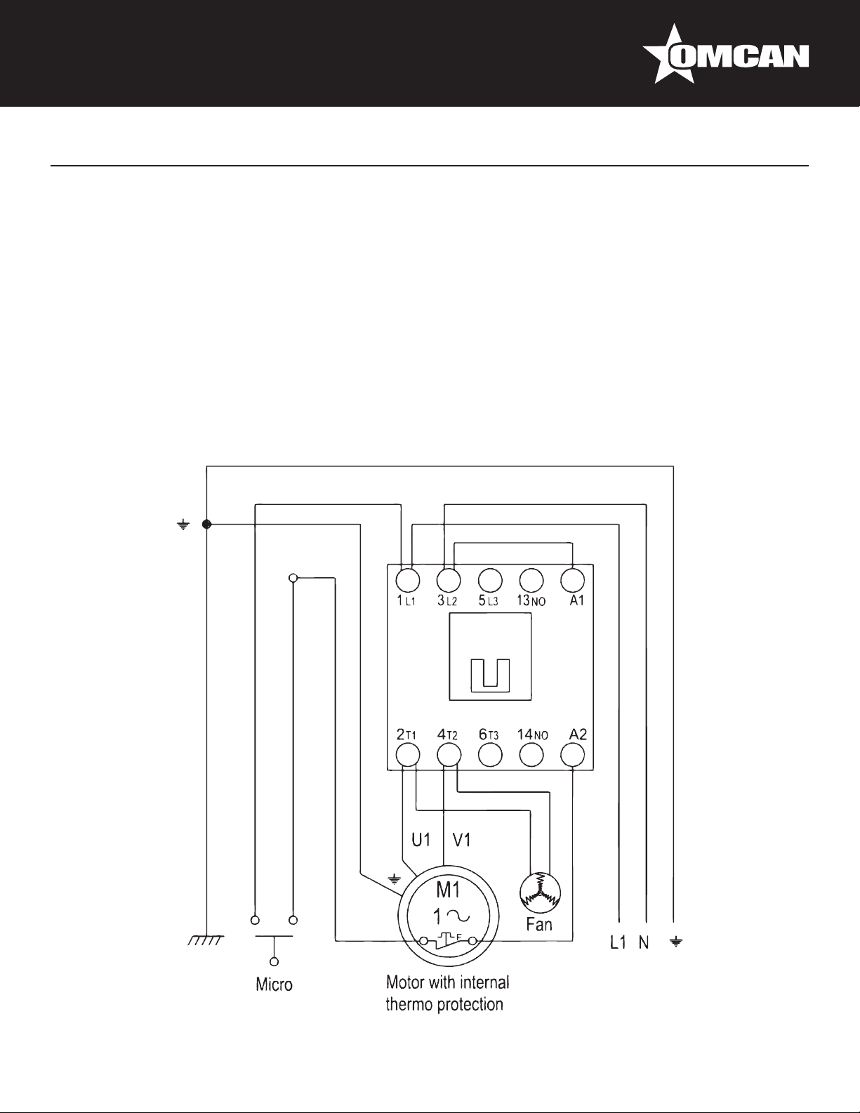
Electrical Schematics
Model SS-ES-0026-F 45950
Model SS-ES-0026-FS 46098
Model SS-ES-0048-F 45959
Model SS-ES-0048-FS 45920
Model SS-ES-0065-F 45870
Model SS-ES-0065-FS 46101
Model SS-ES-0095-F 45951
Model SS-ES-0095-FS 46102
42
Page 43

Model SS-ES-0026-FT 46099
Model SS-ES-0048-FT 45869
Model SS-ES-0065-FT 46100
Model SS-ES-0095-FT 46103
Electrical Schematics
43
Page 44

Notes
44
Page 45

Notes
45
Page 46

Notes
46
Page 47

Warranty Registration
Thank you for purchasing an Omcan product. To register your warranty for this product, complete the information below, tear off the card at
the perforation and then send to the address specied below. You can also register online by visiting:
Merci d’avoir acheté un produit Omcan. Pour enregistrer votre garantie pour ce produit, complétez les informations ci-dessous, détachez la
carte au niveau de la perforation, puis l’envoyer à l’adresse spécié ci-dessous. Vous pouvez également vous inscrire en ligne en visitant:
Gracias por comprar un producto Omcan usted. Para registrar su garantía para este producto, complete la información a continuación,
cortar la tarjeta en la perforación y luego enviarlo a la dirección indicada a continuación. También puede registrarse en línea en:
https://omcan.com/warranty-registration/
For mailing in Canada
Pour postale au Canada
Por correo en Canadá
OMCAN
PRODUCT WARRANTY REGISTRATION
3115 Pepper Mill Court,
Mississauga, Ontario
Canada, L5L 4X5
PRODUCT WARRANTY REGISTRATION
4450 Witmer Industrial Estates, Unit 4,
For mailing in the US
Pour diffusion aux États-Unis
Por correo en los EE.UU.
OMCAN
Niagara Falls, New York
USA, 14305
or email to: service@omcan.com
Purchaser’s Information
Name: Company Name:
Address:
Telephone:
City: Province or State: Postal or Zip: Email Address:
Country: Type of Company:
Restaurant Bakery Deli
Dealer from which Purchased: Butcher Supermarket Caterer
Dealer City: Dealer Province or State: Institution (specify):
Invoice: Other (specify):
Model Name: Model Number: Serial Number:
Machine Description:
Date of Purchase (MM/DD/YYYY): Date of Installation (MM/DD/YYYY):
Would you like to extend the warranty? Yes No
Thank you for choosing Omcan | Merci d’avoir choisi Omcan | Gracias por elegir Omcan
47
Page 48

Since 1951 Omcan has grown to become a leading distributor of equipment and supplies to the North
American food service industry. Our success over these many years can be attributed to our commitment
to strengthen and develop new and existing relationships with our valued customers and manufacturers.
Today with partners in North America, Europe, Asia and South America, we continually work to improve
and grow the company. We strive to offer customers exceptional value through our qualied local sales
and service representatives who provide convenient access to over 5,000 globally sourced products.
Depuis 1951 Omcan a grandi pour devenir un des “leaders” de la distribution des équipements et
matériel pour l’industrie des services alimentaires en Amérique du Nord. Notre succès au cours de ces
nombreuses années peut être attribué à notre engagement à renforcer et à développer de nouvelles
et existantes relations avec nos clients et les fabricants de valeur. Aujourd’hui avec des partenaires en
Amérique du Nord, Europe, Asie et Amérique du Sud, nous travaillons continuellement à améliorer et
développer l’entreprise. Nous nous efforçons d’offrir à nos clients une valeur exceptionnelle grâce à
nos ventes locales qualiées et des représentants de service qui offrent un accès facile à plus de 5000
produits provenant du monde entier.
Desde 1951 Omcan ha crecido hasta convertirse en un líder en la distribución de equipos y suministros
de alimentos en América del Norte industria de servicios. Nuestro éxito en estos años se puede atribuir
a nuestro compromiso de fortalecer y desarrollar nuevas relaciones existentes con nuestros valiosos
clientes y fabricantes. Hoy con socios de América del Norte, Europa, Asia y América del Sur, que trabajan
continuamente para mejorar y crecer la empresa. Nos esforzamos por ofrecer a nuestros clientes valor
excepcional a través de nuestro local de ventas y representantes de los servicios que proporcionan un
fácil acceso a más de 5,000 productos con origen a nivel mundial.
 Loading...