

Page 1
Reach In Coolers and Freezers
Models RE-CN-0021-HC, 0041-HC, 0067-HC,
FR-CN-0737-HC, 1372-HC, 2057-HC
Items 50024, 50026, 50028, 50023, 50025, 50027
Instruction Manual
Revised - 08/22/2019
Toll Free: 1-800-465-0234
Fax: 905-607-0234
Email: service@omcan.com
www.omcan.com
Page 2

Table of Contents
Model RE-CN-0021-HC / Model RE-CN-0041-HC / Model RE-CN-0067-HC
Model FR-CN-0737-HC / Model FR-CN-1372-HC / Model FR-CN-2057-HC
Section
General Information
Safety and Warranty
Technical Specications
Installation
Maintenance
Troubleshooting
--------------------------------------------------------------------------------------- 7 - 8
------------------------------------------------------------------------------------- 8 - 9
--------------------------------------------------------------------------- 3 - 4
--------------------------------------------------------------------------- 4 - 5
----------------------------------------------------------------------------- 10 - 11
Page
---------------------------------------------------------------------- 6 - 7
Controller Instructions
Parts Breakdown
Electrical Schematics
Notes
Warranty Registration
------------------------------------------------------------------------------------------- 33 - 34
---------------------------------------------------------------------------- 18 - 29
--------------------------------------------------------------------- 12 - 17
---------------------------------------------------------------------- 30 - 32
---------------------------------------------------------------------------- 35
2
Page 3

General Information
Omcan Manufacturing and Distributing Company Inc., Food Machinery of America, Inc. dba Omcan
and Omcan Inc. are not responsible for any harm or injury caused due to any person’s improper or
negligent use of this equipment. The product shall only be operated by someone over the age of 18, of
sound mind, and not under the inuence of any drugs or alcohol, who has been trained in the correct
operation of this machine, and is wearing authorized, proper safety clothing. Any modication to the
machine voids any warranty, and may cause harm to individuals using the machine or in the vicinity of
the machine while in operation.
CHECK PACKAGE UPON ARRIVAL
Upon receipt of an Omcan shipment please inspect for external damage. If no damage is evident on the
external packaging, open carton to ensure all ordered items are within the box, and there is no concealed
damage to the machine. If the package has suffered rough handling, bumps or damage (visible or concealed),
please note it on the bill of lading before accepting the delivery and contact Omcan within 24 hours, so we may
initiate a claim with the carrier. A detailed report on the extent of the damage caused to the machine must be
lled out within three days, from the delivery date shown in the shipping documents. Omcan has no recourse
for damaged products that were shipped collect or third party.
Before operating any equipment, always read and familiarize yourself with all operation and safety
instructions.
Omcan would like to thank you for purchasing this machine. It’s of the utmost importance to save
these instructions for future reference. Also save the original box and packaging for shipping the
equipment if servicing or returning of the machine is required.
---------------------------------------------------------------------------------------------------------------------------------------------------
Omcan Fabrication et distribution Companie Limité et Food Machinery d’Amerique, dba Omcan et
Omcan Inc. ne sont pas responsables de tout dommage ou blessure causé du fait que toute personne
ait utilisé cet équipement de façon irrégulière. Le produit ne doit être exploité que par quelqu’un de
plus de 18 ans, saine d’esprit, et pas sous l’inuence d’une drogue ou d’acohol, qui a été formé pour
utiliser cette machine correctement, et est vêtu de vêtements de sécurité approprié. Toute modication
de la machine annule toute garantie, et peut causer un préjudice à des personnes utilisant la machine
ou des personnes à proximité de la machine pendant son fonctionnement.
VÉRIFIEZ LE COLIS DÈS RÉCEPTION
Dès réception d’une expédition d’Omcan veuillez inspecter pour dommages externes. Si aucun dommage
n’est visible sur l’emballage externe, ouvrez le carton an de s’assurer que tous les éléments commandés
sont dans la boîte, et il n’y a aucun dommage dissimulé à la machine. Si le colis n’a subi aucune mauvaises
manipulations, de bosses ou de dommages (visible ou cachée), notez-le sur le bond de livraison avant
d’accepter la livraison et contactez Omcan dans les 24 heures qui suivent, pour que nous puissions engager
une réclamation auprès du transporteur. Un rapport détaillé sur l’étendue des dommages causés à la machine
doit être rempli dans un délai de trois jours, à compter de la date de livraison indiquée dans les documents
d’expédition. Omcan n’a aucun droit de recours pour les produits endommagés qui ont été expédiées ou cueilli
par un tiers transporteur.
3
Page 4

General Information
Avant d’utiliser n’importe quel équipement, toujours lire et vous familiariser avec toutes les opérations
et les consignes de sécurité.
Omcan voudrais vous remercier d’avoir choisi cette machine. Il est primordial de conserver ces
instructions pour une référence ultérieure. Également conservez la boîte originale et l’emballage pour
l’expédition de l’équipement si l’entretien ou le retour de la machine est nécessaire.
---------------------------------------------------------------------------------------------------------------------------------------------------
Omcan Empresa De Fabricacion Y Distribucion Inc. Y Maquinaria De Alimentos De America, Inc. dba
Omcan y Omcan Inc. no son responsables de ningun daño o perjuicío causado por cualquier persona
inadecuada o el uso descuidado de este equipo. El producto solo podra ser operado por una persona
mayor de 18 años, en su sano juicio y no bajo alguna inuencia de droga o alcohol, y que este ha sido
entrenado en el correcto funcionamiento de esta máquina, y ésta usando ropa apropiada y autorizada.
Cualquier modicación a la máquina anúla la garantía y puede causar daños a las personas usando la
máquina mientras esta en el funcionamiento.
REVISE EL PAQUETE A SU LLEGADA
Tras la recepcion de un envio Omcan favor inspeccionar daños externos. Si no hay daños evidentes en el
empaque exterior, Habra el carton para asegurararse que todos los articulos solicitados ésten dentro de la
caja y no encuentre daños ocultos en la máquina. Si el paquete ha sufrido un manejo de poco cuidado, golpes
o daños (visible o oculto) por favor anote en la factura antes de aceptar la entrega y contacte Omcan dentro
de las 24 horas, de modo que podamos iniciar una reclamación con la compañia. Un informe detallado sobre
los daños causados a la máquina debe ser llenado en el plazo de tres días, desde la fecha de entrega que se
muestra en los documentos de envío. Omcan no tiene ningun recurso por productos dañados que se enviaron
a recoger por terceros.
Antes de utilizar cualquier equipo, siempre lea y familiarizarse con todas las instrucciones de
funcionamiento y seguridad.
Omcan le gustaría darle las gracias por la compra de esta máquina. Es de la mayor importancia para
salvar estas instrucciones para futuras consultas. Además, guarda la caja original y el embalaje para el
envío del equipo si servicio técnico o devolución de la máquina que se requiere.
Safety and Warranty
Please pay close attention to the safety notices in this section. Disregarding these notices may lead to
serious injury and/or damage to the unit.
ATTENTION
• To minimize shock and re hazards, be sure not to overload outlet. Please designate one outlet for your
unit.
4
Page 5

Safety and Warranty
• Do not use extension cords.
• Do not put your hands under the unit when the units is required to be moved.
• When the unit is not in use for a long period of time, please unplug the unit from the outlet.
• After unplugging the unit, wait at least 10 minutes before re-plugging it. Failure to do so could cause
damage to the compressor.
UNPLUG CORD
• To minimize shock and re hazards, please do not plug or unplug the cord with wet hands.
• During maintenance and cleaning, please unplug the unit.
PROPER GROUNDING REQUIRED
• To minimize shock and re hazards, make sure that the unit is properly grounded.
PROHIBITION
• Do not attempt to remove or repair any component unless instructed by factory.
• Make sure that the unit is not resting on or against the electrical cord and plug.
• To minimize personal injury, do not hang on the doors.
• Do not store any ammable and explosive gas or liquids inside the unit.
• Do not attempt to alter or tamper with the electrical cord.
2 YEARS PARTS AND LABOUR / 5 YEARS PARTS ONLY ON COMPRESSOR
WARRANTY
Within the warranty period, contact Omcan Inc. at 1-800-465-0234 to schedule an Omcan authorized
service technician to repair the equipment locally.
Unauthorized maintenance will void the warranty. Warranty covers electrical and part failures, not
improper use.
Please see https://omcan.com/disclaimer for complete info.
WARNING:
The packaging components are classied as normal solid urban waste and can therefore be disposed of
without difculty.
In any case, for suitable recycling, we suggest disposing of the products separately (differentiated
waste) according to the current norms.
DO NOT DISCARD ANY PACKAGING MATERIALS IN THE ENVIRONMENT!
5
Page 6
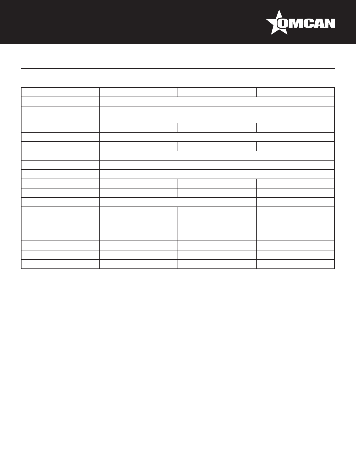
Technical Specications
REACH IN COOLERS
Model RE-CN-0021 RE-CN-0041 RE-CN-0067
Temperature Range 0.5°C -5°C / 33°F - 41°F
Max Ambient Temp
Rating
Horsepower 1/5 HP 1/4 HP 3/4 HP
Electrical 110V / 60Hz / 1Ph
Amps 2.6A 3.8A 9A
Refrigerant R290
Isolation Material Cyclopentane
Cooling System Ventilated
Number of Doors 1 2 3
Number of Shelves 3 6 9
Shelf Capacity 59.5 lbs. / 27 kgs. 61.7 lbs. / 28 kgs.
Exterior Dimensions
Interior Dimensions
Net Volume 650 L / 23 cu.ft. 1334 L / 47 cu.ft. 2040 L / 72 cu.ft.
Weight 282 lbs. / 128 kgs. 513 lbs. / 232.7 kgs. 616 lbs. / 280 kgs.
Item Number 50024 50026 50028
29” x 32.25” x 82.5”
736 x 818 x 2095mm
24.4” x 27” x 60.2”
620 x 688 x 1530mm
32°C / 90°F
54” x 32.25” x 82.5”
1372 x 819 x 2096mm
49.4” x 27” x 60.2”
1255 x 686 x 1529mm
81” x 32” x 82.5”
2054 x 818 x 2095mm
76” x 27” x 60”
1938 x 688 x 1530mm
6
Page 7
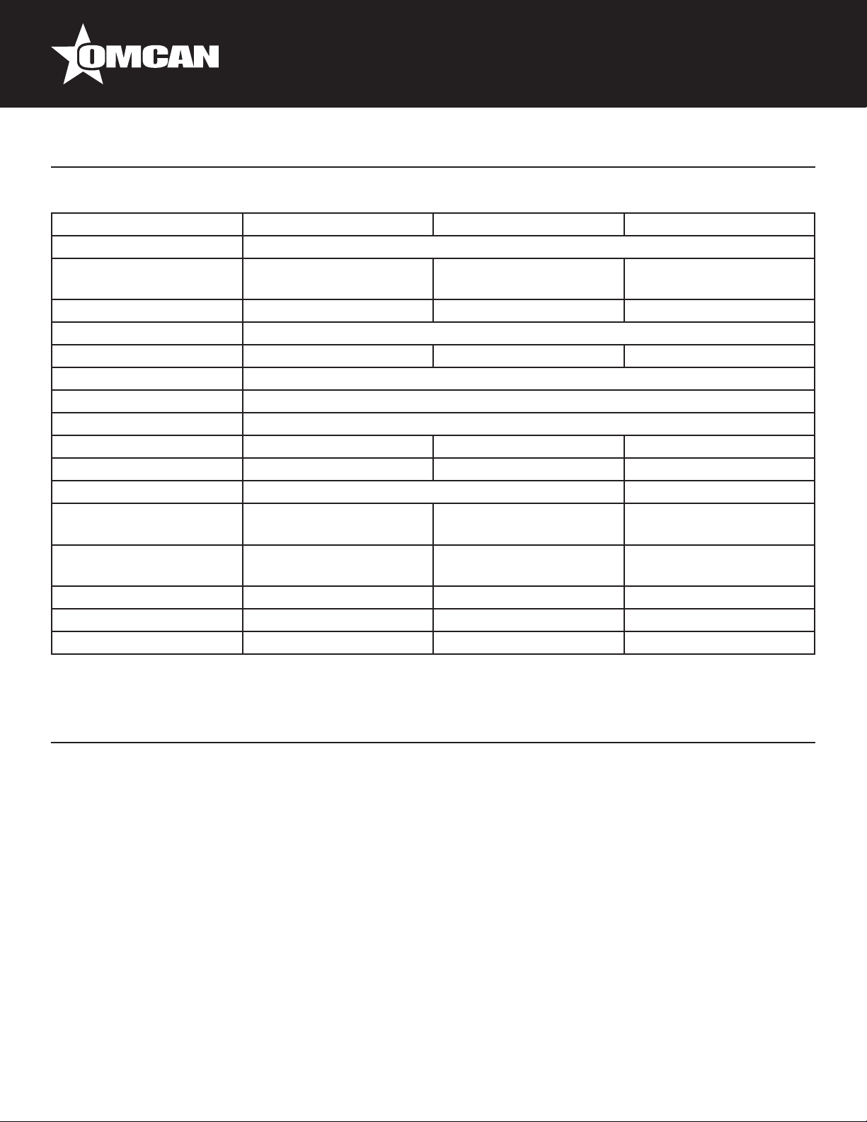
Technical Specications
REACH IN FREEZERS
Model FR-CN-0737 FR-CN-1372 FR-CN-2057
Temperature Range -22°C ~ -18°C / -8°F ~ 0°F
Max Ambient Temp
Rating
Horsepower 1/2 HP 1 HP 1 1/4
Electrical 110V / 60Hz / 1Ph
Amps 7.1A 10.7A 12A
Refrigerant R290
Isolation Material Cyclopentane
Cooling System Ventilated
Number of Doors 1 2 3
Number of Shelves 3 6 9
Shelf Capacity 59.5 lbs. / 27 kgs. 61.7 lbs. / 28 kgs.
Exterior Dimensions
Interior Dimensions
Net Volume 650 L / 23 cu.ft. 1334 L / 47 cu.ft. 2040 L / 72 cu.ft.
Weight 282 lbs. / 128 kgs. 496 lbs. / 225 kgs. 673 lbs. / 306 kgs.
Item Number 50023 50025 50027
29” x 32.25” x 82.5”
736 x 818 x 2095mm
24.4” x 27” x 60.2”
620 x 688 x 1530mm
90°F 100.4°F 90°F
54” x 32.25” x 82.5”
1372 x 819 x 2096mm
49.4” x 27” x 60.2”
1255 x 686 x 1529mm
81” x 32” x 82.5”
2054 x 818 x 2095mm
76” x 27” x 60”
1938 x 688 x 1530mm
Installation
IMPORTANT!!!PLEASE READ BEFORE INSTALLATION
• If the unit has recently been transported. Please let unit stand still for a minimum of 24 hours before
plugging it in.
• Make sure that the unit drops down to desired temperature before loading the unit with product.
• Maker sure that there is proper ventilation around the unit in the area where it will operate.
• Make sure all accessories are installed(i.e. shelves, shelf clips, casters) before plugging the unit in.
• Please read through the Operation / Owners Manual in its entirety.
CABINET LOCATION GUIDELINES
• Install the unit on strong and leveled surfaces
- unit may make unpleasant noises if surface is uneven
- unit may malfunction if surface is uneven
7
Page 8

Installation
• Install the unit in an indoor, well-ventilated area
- unit performs more efciently in a well-ventilated area
- for best performance, please maintain clearance of 6” on the back of the unit
- outdoor use may cause decreased efciency and damage to the unit
• Avoid installation in a high humidity and/or dusty area
- humidity could cause unit to rust and decrease efciency of the unit
- dust collected on condenser coil will cause unit to malfunction. Clean the condenser at least once a month
with a brush or clean cloth
• Select a location away from heat and moisture-generating equipment
- high ambient temperature will cause the compressor to overwork, leading to higher energy bills and
gradual breakdown of the unit.
ELECTRICAL
Please ensure that the required voltage of the compressor is being supplied at all times. Low or high voltage
can detrimentally affect the refrigeration unit. All units should be plugged into a grounded and properly-sized
electrical outlet with appropriate overcurrent protection. Please refer to the electrical requirement on the
nameplate. Please make sure that your unit has its own dedicated outlet. Do not use an extension cord.
REVERSING THE DOORS (OPTIONAL)
Note: This only applies to the single door units.
Only perform these steps with another person present to ensure the door does not fall over.
1. Open the door.
2. Remove the screws from the top panel, then open the top panel.
3. Remove the screws of the bottom louver, then remove the louver.
4. Unscrew all of the screws from the upper hinge
5. Unscrew all of the screws from the lower hinge and remove the door and hinges.
6. Place the former upper hinge at the bottom of the unit, parallel to where the lower hinge is, do the same
with the former lower hinge except for the top. Screw the hinges into place.
7. Reassemble the door so it is facing the opposite direction.
8. Reassemble the top panel and the lower louver.
9. The door is now reversed.
Maintenance
CLEANING THE CONDENSER COIL
• For efcient operation, it is important that the condenser surface be kept free of dust, dirt, and lint.
• We recommend cleaning the condenser coil and ns at least once per month.
• Clean with a commercial condenser coil cleaner, available from any kitchen equipment retailer. Brush the
8
Page 9

Maintenance
condenser ns from top to bottom, not side to side.
• After cleaning, straighten any bent condenser ns with a n comb.
CLEANING THE FAN BLADE AND MOTOR
• If necessary, clean the fan blades and motor with a soft cloth, If it is necessary to wash the fan blades,
cover the fan motor to prevent moisture damage.
CLEANING THE INTERIOR OF UNIT
• When cleaning the cabinet interior, use a solvent of warm water and mild soap.
• Do not use steel wool, caustic soap, abrasive cleaners, or bleach that may damage the stainless steel
surface.
• Wash door gaskets on a regular basis, preferably weekly. Simply remove door gasket from the frame of the
door, soak in warm water and soap for thirty (30) minutes, dry with soft cloth, and replace.
• Check door gaskets for proper seal after they are replaced.
• Periodically remove the shelves and pilasters from the unit and clean them with mild soap and warm water.
To remove the pilasters, rst remove the shelves and shelf brackets. Then, simply lift the pilaster up and
out.
WARNING
Disconnect power cord before cleaning any parts of the unit.
ICE ACCUMULATION MAY OCCUR IN FREEZERS
• Try to reduce the amount of time the freezer doors remain open to prevent ice accumulation.
• Keep door seals clean to prevent air leakage.
• Scrape off any ice accumulated or try manual defrost mode.
9
Page 10

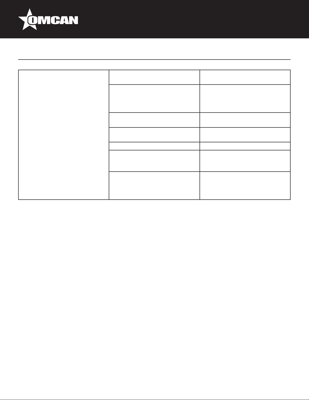
Troubleshooting
Before requesting any service on your unit, please check the following points. Please note that this guide serve
only as a reference for solutions to common problems.
SYMPTOM POSSIBLE CAUSE CORRECTIVE ACTION
Compressor not running. Fuse blown or circuit breaker
tripped.
Power cord unplugged. Plug in power cord.
Thermostat set too high. Set thermostat to lower
Cabinet in defrost cycle. Wait for defrost cycle to nish.
Cabinet is noisy. Loose part(s). Locate and tighten loose part(s).
Tubing vibration. Ensure tubing is free from contact
Condensing unit runs for long
periods of time.
Excessive amount of warm product
Placed in cabinet.
Prolonged door opening or door
ajar.
Door gasket(s) not sealing
properly.
Dirty condenser coil. Clean the condenser coil.
Evaporator coil iced over. Unplug unit and allow coil to
Replace fuse or reset circuit
breaker.
Temperature.
with other tubing or components.
Allow adequate time for Product to
cool down.
Ensure doors are closed when not
in use. Avoid opening doors for
long periods of time.
Ensure gaskets are snapped in
Completely. Remove gasket and
Wash with soap and water. Check
condition of gasket and Replace if
necessary.
defrost. Make sure thermostat is
not set too cold. Ensure that door
gasket(s) are sealing properly.
10
Page 11
Troubleshooting
Cabinet Temperature Is too warm. Thermostat set too warm. Set thermostat to lower
Temperature.
Blocking air ow. Re-arrange product to allow for
Proper air ow. Make sure there
Is at least four inches of clearance
from evaporator.
Excessive amount of warm product
Placed in cabinet.
Fuse blown or circuit breaker
tripped.
Dirty condenser coil. Clean the condenser coil.
Prolonged door opening or door
ajar.
Evaporator coil iced over. Unplug unit and allow coil to
Allow adequate time for product to
cool down.
Replace fuse or reset circuit
breaker.
Ensure doors are closed when not
in use. Avoid opening doors for
long periods of time.
defrost. Make sure thermostat is
not set too cold. Ensure that door
gasket(s) are sealing properly.
11
Page 12

Controller Instructions
Digital controller model: PJEZ for cooler
Display and functions
During normal operation, the controller displays the value of the probe set using parameter/4(=1 ambient
probe, default, = 2 second probe, = 3 third probe).In addition, the display has LEDs that indicate the activation
of the control functions (see Table 1), while the 3 buttons can be used to activate/deactivate some of the
functions(see Table 2).
LED’s and Associated Functions (Table 1)
Icon Function Normal Operation Start Up
ON OFF Blink
Compressor On Off Request ON
Fan On Off Request ON
Defrost On Off Request ON
Aux Output On Output Off - ON
Alarm All No Alarm - ON
Clock RTC tted and enabled, at
least 1 time band set
RTC not tted or disabled, not
even 1 time band set
- ON if RTC
tted
12
Page 13

Controller Instructions
Table of Functions activated by the buttons - Models S, X, Y, C (Table 2)
Button Normal Operation Start Up
Pressing the Button Alone Pressed Together
Up
ON/OFF
Down
Defrost
Set Mute - 1 sec.: display/set the set
Setting the set point (desired temperature)
More than 3 sec: toggle ON/
OFF
More than 3 sec: start/stop
defrost
point.
- more than 3 secs.: access
parameter setting menu
(enter password )
- mute audible alarm
(buzzer)
Start/Stop
continuous cycle
- For 1 sec.
-
Pressed
together
Start parameter
reset procedure
For 1 sec.
display
rmware
vers. code
RESET current EZY set
• Press SET for 1 sec, the set value will start ashing after a few moments.
• Increase or decrease the value using UP or DOWN.
• Press SET to conrm the new value.
Switching the device ON/OFF
Press UP for more than 3 sec. The control and defrost algorithms are now disabled and the Instrument
displays the message “OFF” alternating with the temperature read by the set probe
Manual defrost
Press for DOWN more than 3 sec (the defrost starts only the temperature conditions are valid).
Continuous cycle
Press UP and DOWN together for more than 3 sec.
Access and setting type F (frequent) and type C (conguration) parameters
1. Press SET for 3 sec (the display will show “PS”).
2. • To access the type F and C parameter menu, enter the password “22” using UP/DOWN, press SET to
conrm.
• To access the F parameter menu only, press SET (without entering the password).
3. Scroll inside the parameter menu using UP/DOWN.
13
Page 14

Controller Instructions
• To display/set the values of the parameter displayed, press SET, then UP/DOWN and nally SET to
conrm the changes (returning to the parameter menu).
To save all the new values and exit the parameter menu, press SET for 3 s.
To exit the menu without saving the changed values (exit by timeout) do not press any button for at least 60 s.
Digital controller model: IR33 for freezer
Signals on the display
The blinking status indicates a request for activation that cannot be implemented until the end of the
Corresponding delay times.
Icon Function ON OFF Blink Startup
Compressor Compressor on Compressor off Request
Fan Fan on Fan off Request
Defrost Defrost in progress Defrost not required Request
Aux Auxiliary Output AUX
active
Alarm Delayed external
alarm (before the
expiry of the time ‘A7’)
Clock At least one timed
defrost has been set
Auxiliary Output
AUX not active
No alarm present Alarms in normal operation
No timed defrost is
present
Anti-sweat heater function
active
(eg. high/low temp.) or
alarm from ext. digital input
immediate or delayed
Clock alarm On if Real-
Time Clock
present
14
Page 15

Controller Instructions
Light Auxiliary output light
active
Service No malfunction Malfunction (eg. EEPROM
HACCP HACCP function HACCP function
Continuous
Cycle
Enabled Not enabled Request
Auxiliary output light
not active
enabled
Anti-sweat heater function
active
error or probe fault)
HACCP alarm (HA and/or
HF) not enabled
Setting the set point (desired temperature value)
To display or set the set point, proceed as follow:
1. Press the “Set” button for more than 1 second to display the set point.
2. Increase or decrease the value of the set point, using the “ ” and “ ” respectively, until reaching the
desired value.
3. Press the “Set” button again to conrm the new value.
Alarms with manual reset
The alarms with manual reset can be reset by pressing the “ ” and “ ” for more than 5 sec.
Manual defrost
As well as the automatic defrost function, a manual defrost can be enabled, if the temperature conditions allow,
by pressing the “ ” button for more than 5 sec.
Continuous cycle
Pressing the buttons “ ” and “ ” simultaneously for more than 5 seconds enables the continuous cycle
function. During operation in continuous cycle, the compressor continues to operate for the time “cc” and
it stops when it reaches the “cc” time out or the minimum temperature has been reached(AL = minimum
temperature alarm threshold). Continuous cycle setting: “cc” parameter (continuous cycle duration): “cc”=0
never active; “c6” parameter (by passing the alarm after the continuous cycle):”cc” = 0 never active; it avoid or
delays the low temperature alarm after the continuous cycle.
Accessing the conguration parameter (type C)
1. Pressing the “ ” and “Set” buttons at the same time for more than 5 sec, the display will show
“00”(password prompt).
2. Use the “ ” or “ ” buttons to display the number “22” (parameter access password).
3. Conrm by pressing “Set”.
4. The display will show the rst modiable “C” parameter.
15
Page 16

Controller Instructions
Accessing the conguration parameter (type F)
1. Hold the “ ” button for more than 5 s (if there are active alarms, rst mute the buzzer), the display will
show the rst modiable “F” parameter.
Modifying the parameters
After having displayed the parameter, either type “C” or type “F”, proceed as follows:
1. Use the “ ” or “ ” buttons to scroll the parameters, until reaching the parameter to be modied; when
scrolling the parameters, an icon is shown on the display that represents the category of the parameter.
2. Alternatively, press the “ ” button to display a menu that can be used to quickly access the family of
parameters to be modied.
3. Scrolling the menu using the “ ” and “ ” buttons displays the codes of the various categories of
parameter, accompanied by the corresponding icon on the display(if present).
4. Once having reached the desired category, press “Set” to go directly to the rst parameter in the chosen
category(if no parameter is visible, pressing the “Set” button will have no effect).
5. At this stage, modify the parameters or return to the “Category” menu, using the “ ” button.
6. Press “Set” to display the value associated with the parameter.
7. Increase or decrease the value using the “ ” or “ ” buttons respectively.
8. Press “Set” to temporarily save the new value and return to the display of the parameter.
9. Repeat the operation from point 1 or point 2.
10. If the parameter has sub-parameters, press “Set” to display the rst sub-parameter.
11. Press the “ ” or “ ” button to display all the sub-parameters.
12. Press “Set” to display the associated value.
13. Increase or decrease the value using the “ ” or “ ” button respectively.
14. Press “Set” to temporarily save the new value and return to the display of the sub-parameter code.
15. Press “ ” to return to the display of the parent parameter.
Saving the new values assigned to the parameters
To denitely save the new values of the modied parameters, press the “ ” button for more than 5 seconds,
thus exiting the parameter setting procedure. All the modication made to the parameters temporarily saved in
the RAM, can be cancelled and “normal operation” resumed by not pressing any button for 60 seconds, thus
allowing the parameter setting session to expire due to timeout if the Instrument is switched off before pressing
the “ ” button, all the modications made to the parameters and temporarily saved will be lost.
16
Page 17

REFERENCE
Controller Instructions
Item Number Model Number Description
Refrigerator 1 Door Stainless Steel
50024 RE-CN-0021-HC
Refrigerator 2 Door Stainless Steel
50026 RE-CN-0041-HC
Refrigerator 3 Door Stainless Steel
50028 RE-CN-0067-HC
Freezer Stainless Steel Single Door
50023 FR-CN-0737-HC
Freezer Stainless Steel Dual Door
50025 FR-CN-1372-HC
Freezer Stainless Steel Triple Door
50027 FR-CN-2057-HC
23 cu.ft. 110V/60/1
cETLus / ETL Sanitation
47 cu.ft. 110V/60/1
cETLus / ETL Sanitation
66.5 cu.ft. 110V/60/1
cETLus / ETL Sanitation
29" / 737mm 110V/60/1
cETLus / ETL Sanitation
54" / 1372mm 110V/60/1
cETLus / ETL Sanitation
81" / 2057mm 110V/60/1
cETLus / ETL Sanitation
Manufacturer Model
Number
CFD-1RR-HC
CFD-2RR-HC
CFD-3RR-HC
CFD-1FF-HC
CFD-2FF-HC
CFD-3FF-HC
17
Page 18

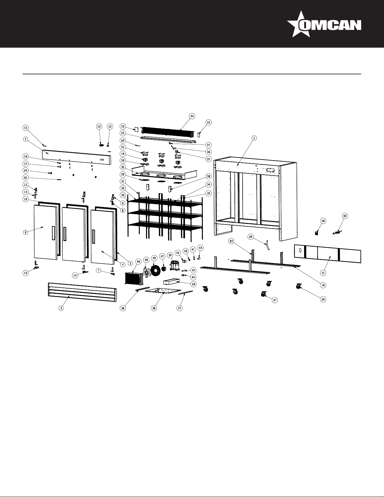
Parts Breakdown
Model RE-CN-0021-HC 50024
18
Page 19

Parts Breakdown
Model RE-CN-0021-HC 50024
Item No. Description Position Item No. Description Position Item No. Description Position
AA950 Cabinet for CFD-1RR-HC 1 AA968 Inner Drain Pan Fixer for CFD-1RR-HC 21 AA764
AA951 Control Panel for CFD-1RR-HC 2 AA969 Drain Hose for CFD-1RR-HC 22 AA984 Condenser Fan Motor for CFD-1RR-HC 45
AA952 Control Panel Fixer for CFD-1RR-HC 3 69703 Elbow Pipe for CFD-1RR-HC 23 AA985 Outer Drain Pan for CFD-1RR-HC 46
AA953 Front Grill for CFD-1RR-HC 4 AA970 Light Components for CFD-1RR-HC 24 AA986 Condenser for CFD-1RR-HC 47
AA954 Upper Right Hinge for CFD-1RR-HC 5 AA971
AA955 Spring Hinge Board for CFD-1RR-HC 6 AA972
AA956 Bottom Right Hinge for CFD-1RR-HC 7 AA973 K Clip for CFD-1RR-HC 27 AA989 Back Grill for CFD-1RR-HC 50
AA957 Door for CFD-1RR-HC 8 AA974 K Strip for CFD-1RR-HC 28 AA124 Power Switch for CFD-1RR-HC 51
AA958 Gasket for CFD-1RR-HC 9 AA975 Shelf for CFD-1RR-HC 29 AA990 Thermostat for CFD-1RR-HC 52
AA959 Hinge for CFD-1RR-HC 10 AA976 Evaporator Cover for CFD-1RR-HC 30 AA844 Door Switch for CFD-1RR-HC 53
AA197 Lock for CFD-1RR-HC 11 AA977
AA960 Lock Bolt for CFD-1RR-HC 12 AA978
AA961 Leg Supporter for CFD-1RR-HC 13 AA979
AA607 Evaporator Fan Motor for CFD-1RR-HC 14 AA980
AA962
AA963
AA964 Right Air Guide Sheet for CFD-1RR-HC 17 AA982 Starter Kit for CFD-1RR-HC 37 - 40 AA121
AA965 Left Air Guide Sheet for CFD-1RR-HC 18 AA129 Filter Fixer for CFD-1RR-HC 41 AA994 Key for CFD-1RR-HC 61
AA966 Evaporator for CFD-1RR-HC 19 AA130 Filter for CFD-1RR-HC 42 AA135 Power Cord for CFD-1RR-HC 62
AA967 Inner Drain Pan for CFD-1RR-HC 20 AA983
Blade of Evaporator Fan Motor for
CFD-1RR-HC
Evaporator Fan Motor Holder for CFD1RR-HC
15 AA981
16 64167 Compressor for CFD-1RR-HC 36 AA216 Drain Hose for CFD-1RR-HC 59
Evaporator Fan Motor Cover for CFD1RR-HC
Bottom Cover for Reversible Door for
CFD-1RR-HC
Top Cover for Reversible Door for CFD1RR-HC
Limited Block of Installation Board for
CFD-1RR-HC
Left Track for Assembling Panel for
CFD-1RR-HC
Right Track for Assembling Panel for
CFD-1RR-HC
Compressor Unit Installation Board for
CFD-1RR-HC
Condenser Fan Motor Holder for CFD1RR-HC
25 AA987 Air Guide Sheet for CFD-1RR-HC 48
26 AA988 Back Grill Fixer for CFD-1RR-HC 49
31 AA991 Drain Plug for CFD-1RR-HC 54
32 AA743 4" Castor for CFD-1RR-HC 55
33 AA584 4" Castor with Brake for CFD-1RR-HC 56
34 AA992 Compressor Fastener for CFD-1RR-HC 57
35 AA993
43
Blade of Condenser Fan Motor for
CFD-1RR-HC
Power Plug Fitting Base for CFD1RR-HC
Temperature Sensor of Cabinet Inside
for CFD-1RR-HC
44
58
60
19
Page 20

Parts Breakdown
Model RE-CN-0041-HC 50026
20
Page 21

Parts Breakdown
Model RE-CN-0041-HC 50026
Item No. Description Position Item No. Description Position Item No. Description Position
AB025 Cabinet for CFD-2RR-HC 1 AB037 Right Air Guide Sheet for CFD-2RR-HC 21 AB017 Condenser for CFD-2RR-HC 44
AB026 Control Panel for CFD-2RR-HC 2 AB038 Left Air Guide Sheet for CFD-2RR-HC 22 AB049 Condenser Fan Motor for CFD-2RR-HC 45
AB027 Front Grill for CFD-2RR-HC 3 AB039 Evaporator for CFD-2RR-HC 23 AA764
AB028 Right Door for CFD-2RR-HC 4 AB040 Inner Drain Pan for CFD-2RR-HC 24 AA249 Condenser Fan Cover for CFD-2RR-HC 47
AB029 Gasket for CFD-2RR-HC 5 AA969 Drain Hose for CFD-2RR-HC 25 AB050 Outer Drain Pan for CFD-2RR-HC 48
AA954 Upper Right Hinge for CFD-2RR-HC 6 69703 Elbow Pipe for CFD-2RR-HC 26 AB051 Back Grill for CFD-2RR-HC 49
AA956 Bottom Right Hinge for CFD-2RR-HC 7 AA970 Light Components for CFD-2RR-HC 27 AA124 Power Switch for CFD-2RR-HC 50
AA955 Spring Hinge Board for CFD-2RR-HC 8 AA971
AB030 Left Door for CFD-2RR-HC 9 AB041 K Clip for CFD-2RR-HC 29 AA844 Door Switch for CFD-2RR-HC 52
AB031 Gasket for CFD-2RR-HC 10 AB042 K Strip for CFD-2RR-HC 30 AB053 Drain Plug for CFD-2RR-HC 53
AB032 Upper Left Hinge for CFD-2RR-HC 11 AB043 Back Brackets for CFD-2RR-HC 31 AA743 4" Castor for CFD-2RR-HC 54
AB033 Left Bottom Hinge for CFD-2RR-HC 12 AA975 Shelf for CFD-2RR-HC 32 AA584 4" Castor with Brake for CFD-2RR-HC 55
AA955 Spring Hinge Board for CFD-2RR-HC 13 AB044 Evaporator Cover for CFD-2RR-HC 33 AA993
AA959 Hinge for CFD-2RR-HC 14 AB045
AA197 Lock for CFD-2RR-HC 15 AB046
AB034 Lock Bolt for CFD-2RR-HC 16 AB047
AB035 Leg Supporter for CFD-2RR-HC 17 64168 Compressor for CFD-2RR-HC 37 AA805 Power Cord for CFD-2RR-HC 60
AA607 Evaporator Fan Motor for CFD-2RR-HC 18 AB048 Starter Kit for CFD-2RR-HC 38 - 41 AB055 Cabinet Supporter for CFD-2RR-HC 61
AA962
AB036
Blade of Evaporator Fan Motor for
CFD-2RR-HC
Evaporator Fan Motor Holder for CFD2RR-HC
19 AA129 Filter Fixer for CFD-2RR-HC 42
20 AA130 Filter for CFD-2RR-HC 43
Evaporator Fan Motor Cover for CFD2RR-HC
Left Track for Assembling Panel for
CFD-2RR-HC
Right Track for Assembling Panel for
CFD-2RR-HC
Compressor Unit Installation Board for
CFD-2RR-HC
28 AB052 Thermostat for CFD-2RR-HC 51
34 AA216 Drain Hose for CFD-2RR-HC 57
35 AA121
36 AB054 Key for CFD-2RR-HC 59
Blade of Condenser Fan Motor for
CFD-2RR-HC
Power Plug Fitting Base for CFD2RR-HC
Temperature Sensor of Cabinet Inside
for CFD-2RR-HC
46
56
58
21
Page 22
Parts Breakdown
Model RE-CN-0067-HC 50028
22
Page 23

Parts Breakdown
Model RE-CN-0067-HC 50028
Item No. Description Position Item No. Description Position Item No. Description Position
AB085 Cabinet for CFD-3RR-HC 1 AB095 Left Air Guide Sheet for CFD-3RR-HC 23 AB076 Condenser for CFD-3RR-HC 46
AB086 Control Panel for CFD-3RR-HC 2 AB096 Evaporator for CFD-3RR-HC 24 AB049 Condenser Fan Motor for CFD-3RR-HC 47
AB087 Front Grill for CFD-3RR-HC 3 AB097 Inner Drain Pan for CFD-3RR-HC 25 AA814
AB088 Right Door for CFD-3RR-HC 4 AA969 Drain Hose for CFD-3RR-HC 26 AB077 Condenser Fan Cover for CFD-3RR-HC 49
AB029 Gasket for CFD-3RR-HC 5, 10 69703 Elbow Pipe for CFD-3RR-HC 27 AB107 Outer Drain Pan for CFD-3RR-HC 50
AA954 Upper Right Hinge for CFD-3RR-HC 6 AA970 Light Components for CFD-3RR-HC 28 AB108 Back Grill for CFD-3RR-HC 51
AA956 Bottom Right Hinge for CFD-3RR-HC 7 AA971
AA955 Spring Hinge Board for CFD-3RR-HC 8, 13 AB098 K Clip for CFD-3RR-HC 30 AB109 Thermostat for CFD-3RR-HC 53
AB089 Left Door for CFD-3RR-HC 9 AB099 K Strip for CFD-3RR-HC 31 AA844 Door Switch for CFD-3RR-HC 54
AB032 Upper Left Hinge for CFD-3RR-HC 11 AB100 Back Brackets for CFD-3RR-HC 32 AB110 Drain Plug for CFD-3RR-HC 55
AB033 Left Bottom Hinge for CFD-3RR-HC 12 AA975 Shelf for CFD-3RR-HC 33 AA743 4" Castor for CFD-3RR-HC 56
AB090 Middle Bottom Hinge for CFD-3RR-HC 14 AB101 Middle Shelf for CFD-3RR-HC 34 AA584 4" Castor with Brake for CFD-3RR-HC 57
AA959 Hinge for CFD-3RR-HC 15 AB102 Evaporator Cover for CFD-3RR-HC 35 AA993
AA197 Lock for CFD-3RR-HC 16 AB103
AB091 Lock Bolt for CFD-3RR-HC 17 AB104
AB092 Leg Supporter for CFD-3RR-HC 18 AB105
AA607 Evaporator Fan Motor for CFD-3RR-HC 19 64170 Compressor for CFD-3RR-HC 39 AA805 Power Cord for CFD-3RR-HC 62
AA962
AB093
AB094 Right Air Guide Sheet for CFD-3RR-HC 22 AA130 Filter for CFD-3RR-HC 45
Blade of Evaporator Fan Motor for
CFD-3RR-HC
Evaporator Fan Motor Holder for CFD3RR-HC
20 AB106 Starter Kit for CFD-3RR-HC 40 - 43 AB112 Cabinet Supporter for CFD-3RR-HC 63
21 AA129 Filter Fixer for CFD-3RR-HC 44
Evaporator Fan Motor Cover for CFD3RR-HC
Left Track for Assembling Panel for
CFD-3RR-HC
Right Track for Assembling Panel for
CFD-3RR-HC
Compressor Unit Installation Board for
CFD-3RR-HC
29 AA124 Power Switch for CFD-3RR-HC 52
36 AA216 Drain Hose for CFD-3RR-HC 59
37 AA121
38 AB 111 Key for CFD-3RR-HC 61
Blade of Condenser Fan Motor for
CFD-3RR-HC
Power Plug Fitting Base for CFD3RR-HC
Temperature Sensor of Cabinet Inside
for CFD-3RR-HC
48
58
60
23
Page 24

Parts Breakdown
Model FR-CN-0737-HC 50023
24
Page 25

Parts Breakdown
Model FR-CN-0737-HC 50023
Item No. Description Position Item No. Description Position Item No. Description Position
AA995 Cabinet for CFD-1FF-HC 1 AA969 Drain Hose for CFD-1FF-HC 22 AB016 Outer Drain Pan for CFD-1FF-HC 46
AA996 Control Panel for CFD-1FF-HC 2 69703 Elbow Pipe for CFD-1FF-HC 23 AB017 Condenser for CFD-1FF-HC 47
AA997 Control Panel Fixer for CFD-1FF-HC 3 AA970 Light Components for CFD-1FF-HC 24 AB018 Back Grill Fixer for CFD-1FF-HC 48
AA998 Front Grill for CFD-1FF-HC 4 AA971
AA954 Upper Right Hinge for CFD-1FF-HC 5 AA972
AA955 Spring Hinge Board for CFD-1FF-HC 6 AB008 K Clip for CFD-1FF-HC 27 AB020 Thermostat for CFD-1FF-HC 51
AA956 Bottom Right Hinge for CFD-1FF-HC 7 AB009 K Strip for CFD-1FF-HC 28 AA844 Door Switch for CFD-1FF-HC 52
AA999 Door for CFD-1FF-HC 8 AA975 Shelf for CFD-1FF-HC 29 AB021 Drain Plug for CFD-1FF-HC 53
AA958 Gasket for CFD-1FF-HC 9 AB010 Evaporator Cover for CFD-1FF-HC 30 AA743 4" Castor for CFD-1FF-HC 54
AA959 Hinge for CFD-1FF-HC 10 AA977
AA197 Lock for CFD-1FF-HC 11 AB011
AB000 Lock Bolt for CFD-1FF-HC 12 AB012
AB001 Leg Supporter for CFD-1FF-HC 13 AB013
AA607 Evaporator Fan Motor for CFD-1FF-HC 14 AB014
AA962
AB002
AB003 Right Air Guide Sheet for CFD-1FF-HC 17 AA129 Filter Fixer for CFD-1FF-HC 41 AA865 Defrost Heater for CFD-1FF-HC 62
AB004 Left Air Guide Sheet for CFD-1FF-HC 18 AA130 Filter for CFD-1FF-HC 42 AA867 Drain Hose Heater for CFD-1FF-HC 63
AB005 Evaporator for CFD-1FF-HC 19 AA249 Condenser Fan Cover for CFD-1FF-HC 43 AA216 Drain Hose for CFD-1FF-HC 64
AB006 Inner Drain Pan for CFD-1FF-HC 20 AA764
AB007 Inner Drain Pan Fixer for CFD-1FF-HC 21 AA984 Condenser Fan Motor for CFD-1FF-HC 45
Blade of Evaporator Fan Motor for
CFD-1FF-HC
Evaporator Fan Motor Holder for CFD1FF-HC
15 64166 Compressor for CFD-1FF-HC 36 AB023
16 AB015 Starter Kit for CFD-1FF-HC 37 - 40 AB024 Key for CFD-1FF-HC 61
Evaporator Fan Motor Cover for CFD1FF-HC
Bottom Cover for Reversible Door for
CFD-1FF-HC
Top Cover for Reversible Door for
CFD-1FF-HC
Limited Block of Installation Board for
CFD-1FF-HC
Left Track for Assembling Panel for
CFD-1FF-HC
Right Track for Assembling Panel for
CFD-1FF-HC
Compressor Unit Installation Board for
CFD-1FF-HC
Blade of Condenser Fan Motor for
CFD-1FF-HC
25 AB019 Back Grill for CFD-1FF-HC 49
26 AA124 Power Switch for CFD-1FF-HC 50
31 AA584 4" Castor with Brake for CFD-1FF-HC 55
32 AA993
33 AB022 Compressor Fastener for CFD-1FF-HC 57
34 AA121
35 AA864 Drain Pan Heater for CFD-1FF-HC 59
44 AA135 Power Cord for CFD-1FF-HC 65
Power Plug Fitting Base for CFD1FF-HC
Temperature Sensor of Cabinet Inside
for CFD-1FF-HC
Evaporator Temperature Sensor for
CFD-1FF-HC
56
58
60
25
Page 26

Parts Breakdown
Model FR-CN-1372-HC 50025
26
Page 27

Parts Breakdown
Model FR-CN-1372-HC 50025
Item No. Description Position Item No. Description Position Item No. Description Position
AB056 Cabinet for CFD-2FF-HC 1 AB066 Evaporator for CFD-2FF-HC 23 AA814
AB057 Control Panel for CFD-2FF-HC 2 AB067 Inner Drain Pan for CFD-2FF-HC 24 AB077 Condenser Fan Cover for CFD-2FF-HC 47
AB058 Front Grill for CFD-2FF-HC 3 AA969 Drain Hose for CFD-2FF-HC 25 AB078 Outer Drain Pan for CFD-2FF-HC 48
AB059 Right Door for CFD-2FF-HC 4 69703 Elbow Pipe for CFD-2FF-HC 26 AB079 Back Grill for CFD-2FF-HC 49
AB029 Gasket for CFD-2FF-HC 5, 10 AA970 Light Components for CFD-2FF-HC 27 AA124 Power Switch for CFD-2FF-HC 50
AA954 Upper Right Hinge for CFD-2FF-HC 6 AA971
AA956 Bottom Right Hinge for CFD-2FF-HC 7 AB068 K Clip for CFD-2FF-HC 29 AA844 Door Switch for CFD-2FF-HC 52
AA955 Spring Hinge Board for CFD-2FF-HC 8, 13 AB069 K Strip for CFD-2FF-HC 30 AB081 Drain Plug for CFD-2FF-HC 53
AB060 Left Door for CFD-2FF-HC 9 AB070 Back Brackets for CFD-2FF-HC 31 AA743 4" Castor for CFD-2FF-HC 54
AB032 Upper Left Hinge for CFD-2FF-HC 11 AA975 Shelf for CFD-2FF-HC 32 AA584 4" Castor with Brake for CFD-2FF-HC 55
AB033 Left Bottom Hinge for CFD-2FF-HC 12 AB071 Evaporator Cover for CFD-2FF-HC 33 AA993
AA959 Hinge for CFD-2FF-HC 14 AB072
AA197 Lock for CFD-2FF-HC 15 AB073
AB061 Lock Bolt for CFD-2FF-HC
AB062 Leg Supporter for CFD-2FF-HC 17 64169 Compressor for CFD-2FF-HC 37 AA805 Power Cord for CFD-2FF-HC 60
AA607 Evaporator Fan Motor for CFD-2FF-HC 18 AB075 Starter Kit for CFD-2FF-HC 38 - 41 AB083 Cabinet Supporter for CFD-2FF-HC 61
AA962
AB063
AB064 Right Air Guide Sheet for CFD-2FF-HC 21 AB076 Condenser for CFD-2FF-HC 44 AA867 Drain Hose Heater for CFD-2FF-HC 64
AB065 Left Air Guide Sheet for CFD-2FF-HC 22 AB049 Condenser Fan Motor for CFD-2FF-HC 45 AA949 Defrost Heater for CFD-2FF-HC 65
Blade of Evaporator Fan Motor for
CFD-2FF-HC
Evaporator Fan Motor Holder for CFD2FF-HC
16 AB074
19 AA129 Filter Fixer for CFD-2FF-HC 42 AB084
20 AA130 Filter for CFD-2FF-HC 43 AA939 Drain Pan Heater for CFD-2FF-HC 63
Evaporator Fan Motor Cover for CFD2FF-HC
Left Track for Assembling Panel for
CFD-2FF-HC
Right Track for Assembling Panel for
CFD-2FF-HC
Compressor Unit Installation Board for
CFD-2FF-HC
28 AB080 Thermostat for CFD-2FF-HC 51
34 AA216 Drain Hose for CFD-2FF-HC 57
35 AA121
36 AB082 Key for CFD-2FF-HC 59
Blade of Condenser Fan Motor for
CFD-2FF-HC
Power Plug Fitting Base for CFD2FF-HC
Temperature Sensor of Cabinet Inside
for CFD-2FF-HC
Evaporator Temperature Sensor for
CFD-2FF-HC
46
56
58
62
27
Page 28

Parts Breakdown
Model FR-CN-2057-HC 50027
28
Page 29

Parts Breakdown
Model FR-CN-2057-HC 50027
Item No. Description Position Item No. Description Position Item No. Description Position
AB113 Cabinet for CFD-3FF-HC 1 AB123 Evaporator for CFD-3FF-HC 24 AA814
AB114 Control Panel for CFD-3FF-HC 2 AB124 Inner Drain Pan for CFD-3FF-HC 25 AB077 Condenser Fan Cover for CFD-3FF-HC 49
AB115 Front Grill for CFD-3FF-HC 3 AA969 Drain Hose for CFD-3FF-HC 26 AB135 Outer Drain Pan for CFD-3FF-HC 50
AB116 Right Door for CFD-3FF-HC 4 AB125 Elbow Pipe for CFD-3FF-HC 27 AB136 Back Grill for CFD-3FF-HC 51
AB029 Gasket for CFD-3FF-HC 5, 10 AA970 Light Components for CFD-3FF-HC 28 AA124 Power Switch for CFD-3FF-HC 52
AA954 Upper Right Hinge for CFD-3FF-HC 6 AA971
AA956 Bottom Right Hinge for CFD-3FF-HC 7 AB126 K Clip for CFD-3FF-HC 30 AA844 Door Switch for CFD-3FF-HC 54
AA955 Spring Hinge Board for CFD-3FF-HC 8, 13 AB127 K Strip for CFD-3FF-HC 31 AB138 Drain Plug for CFD-3FF-HC 55
AB117 Left Door for CFD-3FF-HC 9 AB128 Back Brackets for CFD-3FF-HC 32 AA743 4" Castor for CFD-3FF-HC 56
AB032 Upper Left Hinge for CFD-3FF-HC 11 AA975 Shelf for CFD-3FF-HC 33 AA584 4" Castor with Brake for CFD-3FF-HC 57
AB033 Left Bottom Hinge for CFD-3FF-HC 12 AB101 Middle Shelf for CFD-3FF-HC 34 AA993
AB090 Middle Bottom Hinge for CFD-3FF-HC 14 AB129 Evaporator Cover for CFD-3FF-HC 35 AA216 Drain Hose for CFD-3FF-HC 59
AA959 Hinge for CFD-3FF-HC 15 AB130
AA197 Lock for CFD-3FF-HC 16
AB118 Lock Bolt for CFD-3FF-HC 17 AB132
AB119 Leg Supporter for CFD-3FF-HC 18 64171 Compressor for CFD-3FF-HC 39 AB140 Cabinet Supporter for CFD-3FF-HC 63
AA607 Evaporator Fan Motor for CFD-3FF-HC 19 AB133 Starter Kit for CFD-3FF-HC 40 - 43 AB084
AA962
AB120
AB121 Right Air Guide Sheet for CFD-3FF-HC 22 AB134 Condenser for CFD-3FF-HC 46 AB142 Defrost Heater for CFD-3FF-HC 67
AB122 Left Air Guide Sheet for CFD-3FF-HC 23 AB049 Condenser Fan Motor for CFD-3FF-HC 47
Blade of Evaporator Fan Motor for
CFD-3FF-HC
Evaporator Fan Motor Holder for CFD3FF-HC
20 AA129 Filter Fixer for CFD-3FF-HC 44 AB141 Drain Pan Heater for CFD-3FF-HC 65
21 AA130 Filter for CFD-3FF-HC 45 AA867 Drain Hose Heater for CFD-3FF-HC 66
AB131
Evaporator Fan Motor Cover for CFD3FF-HC
Left Track for Assembling Panel for
CFD-3FF-HC
Right Track for Assembling Panel for
CFD-3FF-HC
Compressor Unit Installation Board for
CFD-3FF-HC
29 AB137 Thermostat for CFD-3FF-HC 53
36 AA121
37 AB139 Key for CFD-3FF-HC 61
38 AA805 Power Cord for CFD-3FF-HC 62
Blade of Condenser Fan Motor for
CFD-3FF-HC
Power Plug Fitting Base for CFD3FF-HC
Temperature Sensor of Cabinet Inside
for CFD-3FF-HC
Evaporator Temperature Sensor for
CFD-3FF-HC
48
58
60
64
29
Page 30

Electrical Schematics
Model RE-CN-0021-HC 50024
Model RE-CN-0041-HC 50026
30
Page 31

Model RE-CN-0067-HC 50028
Electrical Schematics
Model FR-CN-0737-HC 50023
31
Page 32

Electrical Schematics
Model FR-CN-1372-HC 50025
Model FR-CN-2057-HC 50027
32
Page 33

Notes
________________________________________________________________________________________
________________________________________________________________________________________
________________________________________________________________________________________
________________________________________________________________________________________
________________________________________________________________________________________
________________________________________________________________________________________
________________________________________________________________________________________
________________________________________________________________________________________
________________________________________________________________________________________
________________________________________________________________________________________
________________________________________________________________________________________
________________________________________________________________________________________
________________________________________________________________________________________
________________________________________________________________________________________
________________________________________________________________________________________
________________________________________________________________________________________
________________________________________________________________________________________
________________________________________________________________________________________
________________________________________________________________________________________
________________________________________________________________________________________
________________________________________________________________________________________
________________________________________________________________________________________
________________________________________________________________________________________
________________________________________________________________________________________
33
Page 34

Notes
________________________________________________________________________________________
________________________________________________________________________________________
________________________________________________________________________________________
________________________________________________________________________________________
________________________________________________________________________________________
________________________________________________________________________________________
________________________________________________________________________________________
________________________________________________________________________________________
________________________________________________________________________________________
________________________________________________________________________________________
________________________________________________________________________________________
________________________________________________________________________________________
________________________________________________________________________________________
________________________________________________________________________________________
________________________________________________________________________________________
________________________________________________________________________________________
________________________________________________________________________________________
________________________________________________________________________________________
________________________________________________________________________________________
________________________________________________________________________________________
________________________________________________________________________________________
________________________________________________________________________________________
________________________________________________________________________________________
________________________________________________________________________________________
34
Page 35

Warranty Registration
Thank you for purchasing an Omcan product. To register your warranty for this product, complete the information below, tear off the card at
the perforation and then send to the address specied below. You can also register online by visiting:
Merci d’avoir acheté un produit Omcan. Pour enregistrer votre garantie pour ce produit, complétez les informations ci-dessous, détachez la
carte au niveau de la perforation, puis l’envoyer à l’adresse spécié ci-dessous. Vous pouvez également vous inscrire en ligne en visitant:
Gracias por comprar un producto Omcan usted. Para registrar su garantía para este producto, complete la información a continuación,
cortar la tarjeta en la perforación y luego enviarlo a la dirección indicada a continuación. También puede registrarse en línea en:
https://omcan.com/warranty-registration/
For mailing in Canada
Pour postale au Canada
Por correo en Canadá
OMCAN
PRODUCT WARRANTY REGISTRATION
3115 Pepper Mill Court,
Mississauga, Ontario
Canada, L5L 4X5
PRODUCT WARRANTY REGISTRATION
4450 Witmer Industrial Estates, Unit 4,
For mailing in the US
Pour diffusion aux États-Unis
Por correo en los EE.UU.
OMCAN
Niagara Falls, New York
USA, 14305
or email to: service@omcan.com
Purchaser’s Information
Name: Company Name:
Address:
Telephone:
City: Province or State: Postal or Zip: Email Address:
Country: Type of Company:
Restaurant Bakery Deli
Dealer from which Purchased: Butcher Supermarket Caterer
Dealer City: Dealer Province or State: Institution (specify):
Invoice: Other (specify):
Model Name: Model Number: Serial Number:
Machine Description:
Date of Purchase (MM/DD/YYYY): Date of Installation (MM/DD/YYYY):
Would you like to extend the warranty? Yes No
Thank you for choosing Omcan | Merci d’avoir choisi Omcan | Gracias por elegir Omcan
35
Page 36

Since 1951 Omcan has grown to become a leading distributor of equipment and supplies to the North
American food service industry. Our success over these many years can be attributed to our commitment
to strengthen and develop new and existing relationships with our valued customers and manufacturers.
Today with partners in North America, Europe, Asia and South America, we continually work to improve
and grow the company. We strive to offer customers exceptional value through our qualied local sales
and service representatives who provide convenient access to over 5,000 globally sourced products.
Depuis 1951 Omcan a grandi pour devenir un des “leaders” de la distribution des équipements et
matériel pour l’industrie des services alimentaires en Amérique du Nord. Notre succès au cours de ces
nombreuses années peut être attribué à notre engagement à renforcer et à développer de nouvelles
et existantes relations avec nos clients et les fabricants de valeur. Aujourd’hui avec des partenaires en
Amérique du Nord, Europe, Asie et Amérique du Sud, nous travaillons continuellement à améliorer et
développer l’entreprise. Nous nous efforçons d’offrir à nos clients une valeur exceptionnelle grâce à
nos ventes locales qualiées et des représentants de service qui offrent un accès facile à plus de 5000
produits provenant du monde entier.
Desde 1951 Omcan ha crecido hasta convertirse en un líder en la distribución de equipos y suministros
de alimentos en América del Norte industria de servicios. Nuestro éxito en estos años se puede atribuir
a nuestro compromiso de fortalecer y desarrollar nuevas relaciones existentes con nuestros valiosos
clientes y fabricantes. Hoy con socios de América del Norte, Europa, Asia y América del Sur, que trabajan
continuamente para mejorar y crecer la empresa. Nos esforzamos por ofrecer a nuestros clientes valor
excepcional a través de nuestro local de ventas y representantes de los servicios que proporcionan un
fácil acceso a más de 5,000 productos con origen a nivel mundial.
 Loading...