

Page 1
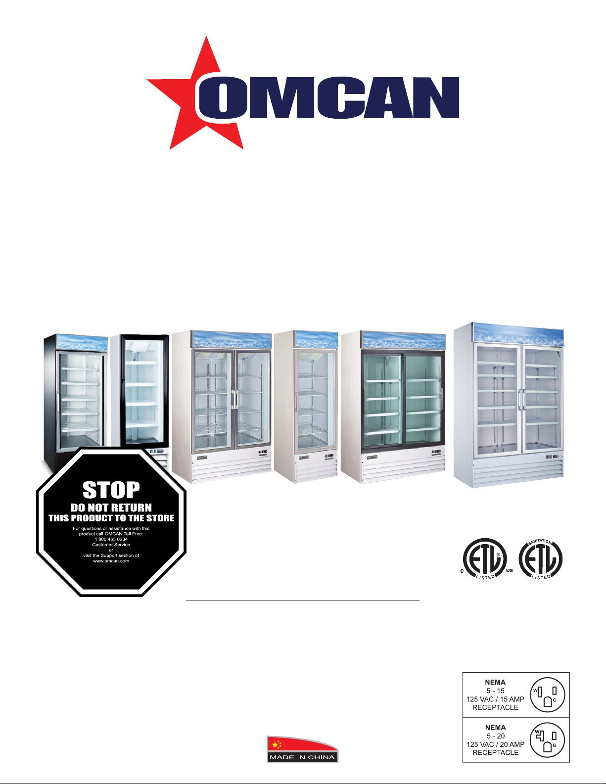
Glass Door Merchandisers
Models RE-CN-0045-HC, 0009-HC, 0014-H, 0023-HC, 0023-H, 0052-HC,
FR-CN-0012-HC, 0790-HC, 1250-HC, 1250-C, 0045-HC
Items 50032, 50033, 50035, 50036, 50037, 50052, 50029, 50030, 50031, 38025, 50075
Instruction Manual
Revised - 08/28/2019
Toll Free: 1-800-465-0234
Fax: 905-607-0234
Email: service@omcan.com
www.omcan.com
Page 2

Table of Contents
Model RE-CN-0045-HC / Model RE-CN-0009-HC / Model RE-CN-0014-H
Model RE-CN-0023-HC / Model RE-CN-0023-H / Model RE-CN-0052-HC
Model FR-CN-0790-HC / Model FR-CN-1250-HC / Model FR-CN-1250-C
FR-CN-0045-HC
Section
General Information
Safety and Warranty
Technical Specications
Installation
Maintenance
Troubleshooting
Controller Instructions
-------------------------------------------------------------------------------------------------- 8
----------------------------------------------------------------------------------------------- 8
---------------------------------------------------------------------------------- 3 - 4
--------------------------------------------------------------------------------- 4 - 5
------------------------------------------------------------------------------------------- 9
Page
---------------------------------------------------------------------------- 6 - 7
---------------------------------------------------------------------------- 10 - 15
Parts Breakdown
Electrical Schematics
Notes
Warranty Registration
------------------------------------------------------------------------------------------------- 41 - 42
---------------------------------------------------------------------------------- 16 - 35
---------------------------------------------------------------------------- 36 - 40
---------------------------------------------------------------------------------- 43
2
Page 3

General Information
Omcan Manufacturing and Distributing Company Inc., Food Machinery of America, Inc. dba Omcan
and Omcan Inc. are not responsible for any harm or injury caused due to any person’s improper or
negligent use of this equipment. The product shall only be operated by someone over the age of 18, of
sound mind, and not under the inuence of any drugs or alcohol, who has been trained in the correct
operation of this machine, and is wearing authorized, proper safety clothing. Any modication to the
machine voids any warranty, and may cause harm to individuals using the machine or in the vicinity of
the machine while in operation.
CHECK PACKAGE UPON ARRIVAL
Upon receipt of an Omcan shipment please inspect for external damage. If no damage is evident on the
external packaging, open carton to ensure all ordered items are within the box, and there is no concealed
damage to the machine. If the package has suffered rough handling, bumps or damage (visible or concealed),
please note it on the bill of lading before accepting the delivery and contact Omcan within 24 hours, so we may
initiate a claim with the carrier. A detailed report on the extent of the damage caused to the machine must be
lled out within three days, from the delivery date shown in the shipping documents. Omcan has no recourse
for damaged products that were shipped collect or third party.
Before operating any equipment, always read and familiarize yourself with all operation and safety
instructions.
Omcan would like to thank you for purchasing this machine. It’s of the utmost importance to save
these instructions for future reference. Also save the original box and packaging for shipping the
equipment if servicing or returning of the machine is required.
---------------------------------------------------------------------------------------------------------------------------------------------------
Omcan Fabrication et distribution Companie Limité et Food Machinery d’Amerique, dba Omcan et
Omcan Inc. ne sont pas responsables de tout dommage ou blessure causé du fait que toute personne
ait utilisé cet équipement de façon irrégulière. Le produit ne doit être exploité que par quelqu’un de
plus de 18 ans, saine d’esprit, et pas sous l’inuence d’une drogue ou d’acohol, qui a été formé pour
utiliser cette machine correctement, et est vêtu de vêtements de sécurité approprié. Toute modication
de la machine annule toute garantie, et peut causer un préjudice à des personnes utilisant la machine
ou des personnes à proximité de la machine pendant son fonctionnement.
VÉRIFIEZ LE COLIS DÈS RÉCEPTION
Dès réception d’une expédition d’Omcan veuillez inspecter pour dommages externes. Si aucun dommage
n’est visible sur l’emballage externe, ouvrez le carton an de s’assurer que tous les éléments commandés
sont dans la boîte, et il n’y a aucun dommage dissimulé à la machine. Si le colis n’a subi aucune mauvaises
manipulations, de bosses ou de dommages (visible ou cachée), notez-le sur le bond de livraison avant
d’accepter la livraison et contactez Omcan dans les 24 heures qui suivent, pour que nous puissions engager
une réclamation auprès du transporteur. Un rapport détaillé sur l’étendue des dommages causés à la machine
doit être rempli dans un délai de trois jours, à compter de la date de livraison indiquée dans les documents
d’expédition. Omcan n’a aucun droit de recours pour les produits endommagés qui ont été expédiées ou cueilli
par un tiers transporteur.
3
Page 4

General Information
Avant d’utiliser n’importe quel équipement, toujours lire et vous familiariser avec toutes les opérations
et les consignes de sécurité.
Omcan voudrais vous remercier d’avoir choisi cette machine. Il est primordial de conserver ces
instructions pour une référence ultérieure. Également conservez la boîte originale et l’emballage pour
l’expédition de l’équipement si l’entretien ou le retour de la machine est nécessaire.
---------------------------------------------------------------------------------------------------------------------------------------------------
Omcan Empresa De Fabricacion Y Distribucion Inc. Y Maquinaria De Alimentos De America, Inc. dba
Omcan y Omcan Inc. no son responsables de ningun daño o perjuicío causado por cualquier persona
inadecuada o el uso descuidado de este equipo. El producto solo podra ser operado por una persona
mayor de 18 años, en su sano juicio y no bajo alguna inuencia de droga o alcohol, y que este ha sido
entrenado en el correcto funcionamiento de esta máquina, y ésta usando ropa apropiada y autorizada.
Cualquier modicación a la máquina anúla la garantía y puede causar daños a las personas usando la
máquina mientras esta en el funcionamiento.
REVISE EL PAQUETE A SU LLEGADA
Tras la recepcion de un envio Omcan favor inspeccionar daños externos. Si no hay daños evidentes en el
empaque exterior, Habra el carton para asegurararse que todos los articulos solicitados ésten dentro de la
caja y no encuentre daños ocultos en la máquina. Si el paquete ha sufrido un manejo de poco cuidado, golpes
o daños (visible o oculto) por favor anote en la factura antes de aceptar la entrega y contacte Omcan dentro
de las 24 horas, de modo que podamos iniciar una reclamación con la compañia. Un informe detallado sobre
los daños causados a la máquina debe ser llenado en el plazo de tres días, desde la fecha de entrega que se
muestra en los documentos de envío. Omcan no tiene ningun recurso por productos dañados que se enviaron
a recoger por terceros.
Antes de utilizar cualquier equipo, siempre lea y familiarizarse con todas las instrucciones de
funcionamiento y seguridad.
Omcan le gustaría darle las gracias por la compra de esta máquina. Es de la mayor importancia para
salvar estas instrucciones para futuras consultas. Además, guarda la caja original y el embalaje para el
envío del equipo si servicio técnico o devolución de la máquina que se requiere.
Safety and Warranty
• To minimize shock and re hazards, be sure not to overload the outlet.
• To minimize electric shock and malfunction, do not spray the unit with water.
• To minimize re hazards, do not use ammable spray products near the unit.
• After unplugging the unit, wait at least 6 minutes before re-plugging it. It may cause compressor failure if
plugged in before 6 minutes waiting period.
• Cautions for cleaning:
- Unplug the power cord before cleaning.
4
Page 5

Safety and Warranty
- Do not unplug-plug the power cord with wet hands.
- Do not use an abrasive cleaners, solvents or polishing agents on plastic parts. Doing so might cause
cracking or discoloring.
• When it is not in use:
- Unplug the power cord.
- Wipe inside with dry cloth, and you may leave the door slightly open to eliminate moisture and odor.
2 YEARS PARTS AND LABOUR / 5 YEARS PARTS ONLY ON COMPRESSOR
WARRANTY
Within the warranty period, contact Omcan Inc. at 1-800-465-0234 to schedule an Omcan authorized
service technician to repair the equipment locally.
Unauthorized maintenance will void the warranty. Warranty covers electrical and part failures, not
improper use.
Please see https://omcan.com/disclaimer for complete info.
WARNING:
The packaging components are classied as normal solid urban waste and can therefore be disposed of
without difculty.
In any case, for suitable recycling, we suggest disposing of the products separately (differentiated
waste) according to the current norms.
DO NOT DISCARD ANY PACKAGING MATERIALS IN THE ENVIRONMENT!
5
Page 6
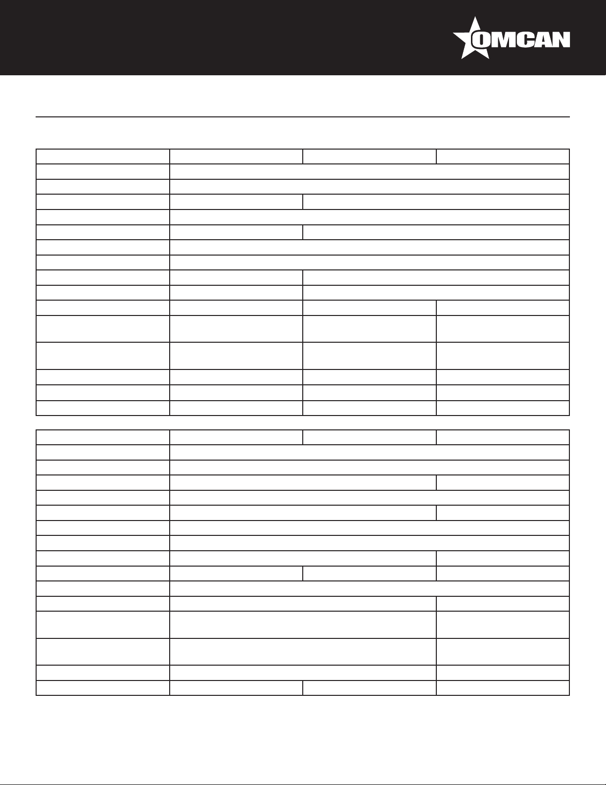
Technical Specications
GLASS DOOR COOLERS
Model RE-CN-0045-HC RE-CN-0009-HC RE-CN-0014-H
Temperature Range 0°C - 5°C / 33°F - 41°F
Max Ambient Temp Rating 32°C / 90°F
Horsepower 1/4 HP 1/5 HP
Electrical 110V / 60Hz / 1Ph
Amps 4.3A 2.88A
Refrigerant R290
Cooling System Ventilated
Number of Doors 2 1
Number of Shelves 8 4
Shelf Capacity 90 lbs. / 40.8 kgs. 55.1 lbs. / 25 kgs. 77 lbs. / 35 kgs.
Exterior Dimensions
Interior Dimensions
Net Volume 1270 L / 45 cu.ft. 257.7 L / 9.1 cu.ft. 398 L / 14 cu.ft.
Weight 441 lbs. / 200 kgs. 161 lbs. / 73 kgs. 220 lbs. / 99.8 kgs.
Item Number 50032 50033 50035
53.25” x 32” x 83.8”
1353 x 813 x 2129mm
50” x 28.5” x 62”
1270 x 724 x 1575mm
21.75” x 21.75” x 63”
552 x 552 x 1600mm
19” x 18” x 46”
483 x 457 x 1168mm
25.6” x 22.8” x 79.4”
650 x 579 x 2017mm
22.8” x 19.8” x 55”
579 x 503 x 1397mm
Model RE-CN-0023-HC RE-CN-0023-H RE-CN-0052-HC
Temperature Range 0°C - 5°C / 33°F - 41°F
Max Ambient Temp Rating 32°C / 90°F
Horsepower 1/5 HP 3/4 HP
Electrical 110V / 60Hz / 1Ph
Amps 3A 10.7A
Refrigerant R290
Cooling System Ventilated
Number of Doors 1 3
Number of Shelves 4 5 12
Shelf Capacity 90 lbs. / 41 kgs.
Net Volume 648 L / 23 cu.ft. 1500.8 L / 53 cu.ft.
Exterior Dimensions
Interior Dimensions
Net Weight 320 lbs. / 145.1 kgs. 615 lbs. / 279 kgs.
Item Number 50036 50037 50052
28.3” x 31.9” x 83.6”
719 x 810 x 2123mm
25.2” x 28.3” x 62.3”
640 x 719 x 1582mm
78.27” x 29.9” x 84.64”
1988 x 759 x 2150mm
73.7” x 25.6” x 55.7”
1872 x 650 x 1415 mm
6
Page 7
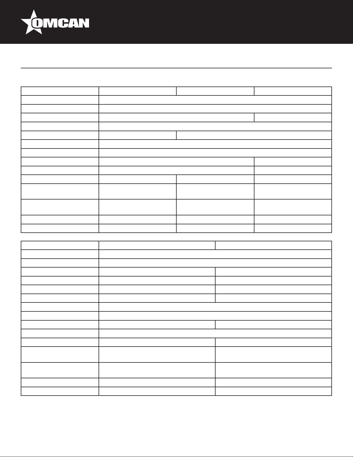
Technical Specications
GLASS DOOR FREEZERS
Model FR-CN-0012-HC FR-CN-0790-HC FR-CN-1250-HC
Temperature Range -23°C - -18°C / -10°F - -0°F
Max Ambient Temp Rating 32°C / 90°F
Horsepower 3/4 HP 0.75 HP
Electrical 110V / 60Hz / 1Ph
Amps 8.8A 9.4A
Refrigerant R290
Cooling System Ventilated
Number of Doors 1 2
Number of Shelves 4 8
Net Volume 368 L / 13 cu.ft. 648 L / 23 cu.ft. 821.2 L / 29 cu.ft.
Exterior Dimensions
Interior Dimensions
Net Weight 374 lbs. / 170 kgs. 506 lbs. / 230 kgs. 397 lbs. / 180.1 kgs.
Item Number 50029 50030 50031
27.2” x 26.2” x 80.3”
691 x 665 x 2040mm
21.3” x 19.3” x 55”
541 x 490 x 1397mm
31” x 33” x 87”
790 x 845 x 2210mm
25.2” x 28.3” x 62”
640 x 720 x 1575mm
49.2” x 26.2” x 84.6”
1250 x 665 x 2149mm
43.3” x 19.3” x 55.1”
1100 x 490 x 1400mm
Model FR-CN-1250-C FR-CN-0045-HC
Temperature Range -23°C - -18°C / -10°F - -0°F
Max Ambient Temp Rating 32°C / 90°F
Horsepower 1 3/5 HP 1 HP
Electrical 110V / 60Hz / 1Ph 115V / 60Hz / 1Ph
Amps 12A 9.2A
Refrigerant R404a R290
Cooling System Ventilated
Number of Doors 2
Number of Shelves 8 10
Shelf Capacity 90 lbs. / 41 kg.
Net Volume 708 L / 25 cu.ft. 1270 L / 45 cu.ft.
Exterior Dimensions
Interior Dimensions
Net Weight 397 lbs. / 180.1 kgs. 573 lbs. / 260 kgs.
Item Number 38025 50075
49.2” x 26.2” x 84.6”
1250 x 665 x 2149mm
43.3” x 19.3” x 55.1”
1100 x 490 x 1400mm
53” x 32” x 79”
1350 x 810 x 2015mm
47” x 25” x 58”
1204 x 635 x 1480mm
7
Page 8

Installation
IMPORTANT!!!PLEASE READ BEFORE INSTALLATION
• The refrigeration system operates most efciently when installed in an area with cool, dry air circulation.
• There must be at least 6 inches of clearance on both sides and the back of the cabinet.
• Select a location away from the heat and moisture generating equipment such as stoves, ovens, etc.
• Avoid direct sun rays.
• Be sure that the oor where you intend to install that unit is strong and level enough to support the total
weight of the unit and its contents.
• To minimize shock and re hazards, be sure that the unit is properly grounded. For your safety and
protection, all units are equipped with a special three-prong grounding plug on the service cord.
• All units are designed for indoor use. Outdoor use may cause signicant damage to the unit.
Maintenance
• When loading the unit:
- Be careful not to block the air duct located at the back and the fan on the ceiling of the unit with contents.
- Blocking the air ow may cause decrease in performance.
- For the best performance, maintain at least 4 inches of clearance between the contents and the air duct.
• Set the shelves that come with the unit to t your needs.
• Temperature controller:
- The controller is located at the right, front corner of the ceiling, or on the front bottom panel.
- To adjust temperature please refer to the manual of temperature controller.
• Do not leave the unit door open for long period of time. For the most efcient operation, close the door
immediately after the use.
ICE ACCUMULATION MAY OCCUR IN FREEZERS
• Try to reduce the amount of time the freezer doors remain open to prevent ice accumulation.
• Keep door seals clean to prevent air leakage.
• Scrape off any ice accumulated or try manual defrost mode.
8
Page 9
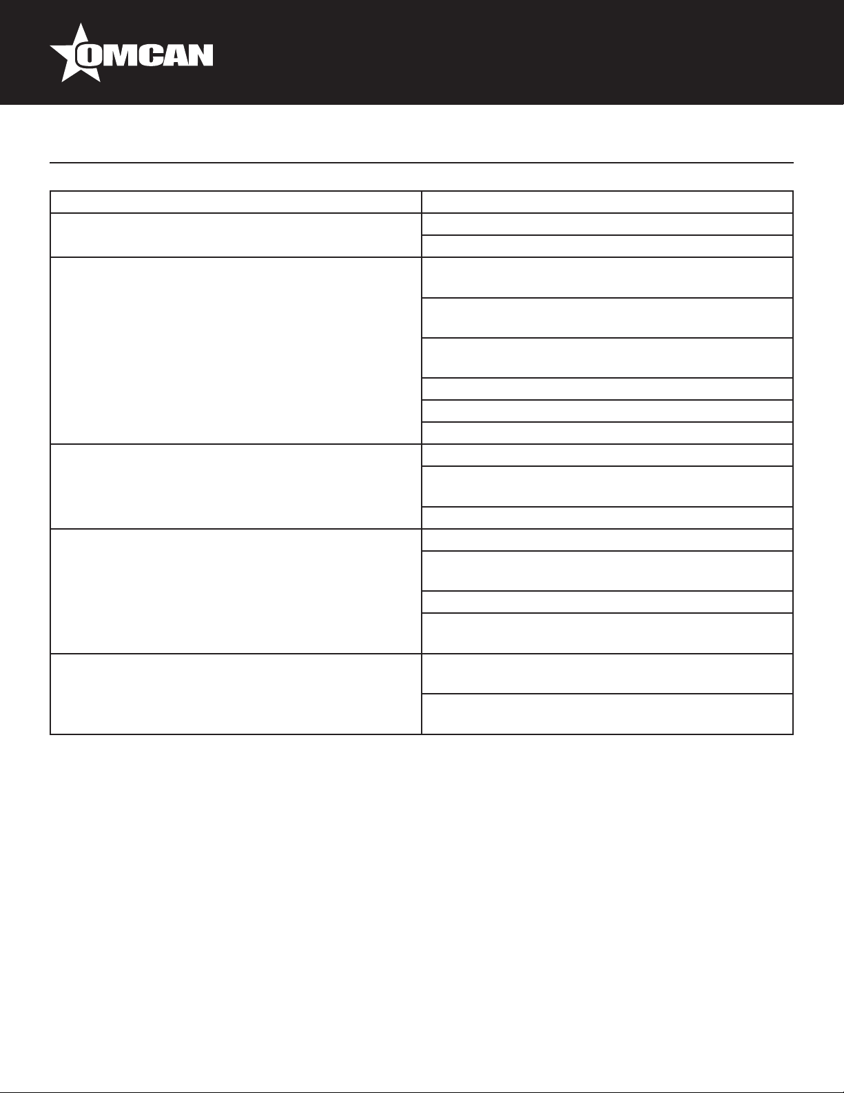
Troubleshooting
SYMPTOMS POSSIBLE CAUSE
Compressor will not start Check if the power cord has been plugged in.
Check for blown fuse.
Poor Performance Move the unit from direct sun light, and avoid
installing heating devices near the unit.
Install the unit in a well ventilated place with minimum
of 6” clearance in the back.
Check the condenser, and clean if heavy dust is
collected.
Check to see if contents are blocking the air duct.
Check to see if refrigerant charge is low.
Make sure the door is completely closed.
No Interior Light Turn off the light switch and turn it on again.
Make sure the light is correctly inserted into the
sockets.
Check the light, and replace it if blown.
Unit Noisy Make sure to install the unit on level surface.
Make sure to maintain the minimum clearance of 6”
from the wall.
Check for the loose parts or mounting.
Make sure the tubing is free from any contact to avoid
tubing rattle.
Condensation on Cabinet and/or Floor Reduce the relatively humidity in the area where the
unit is installed.
Gasket on door or head section is not sealing
properly. Repair or replace gasket as necessary.
9
Page 10
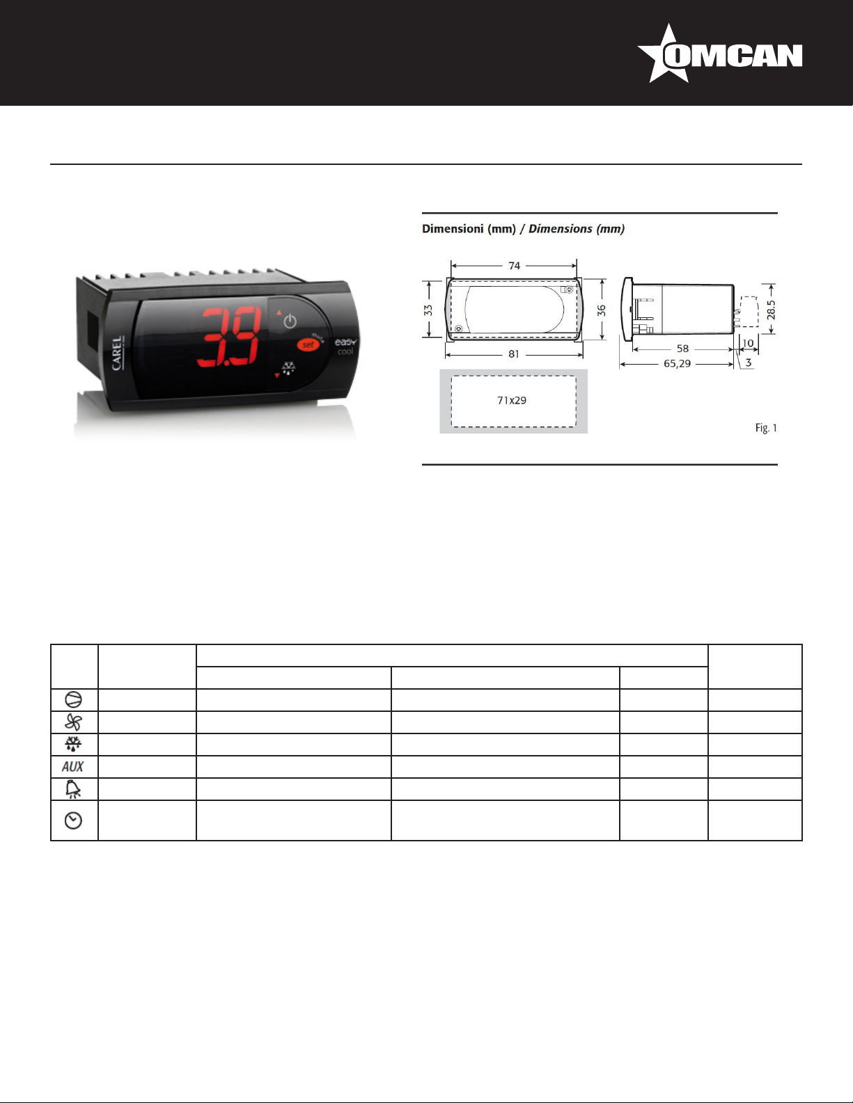
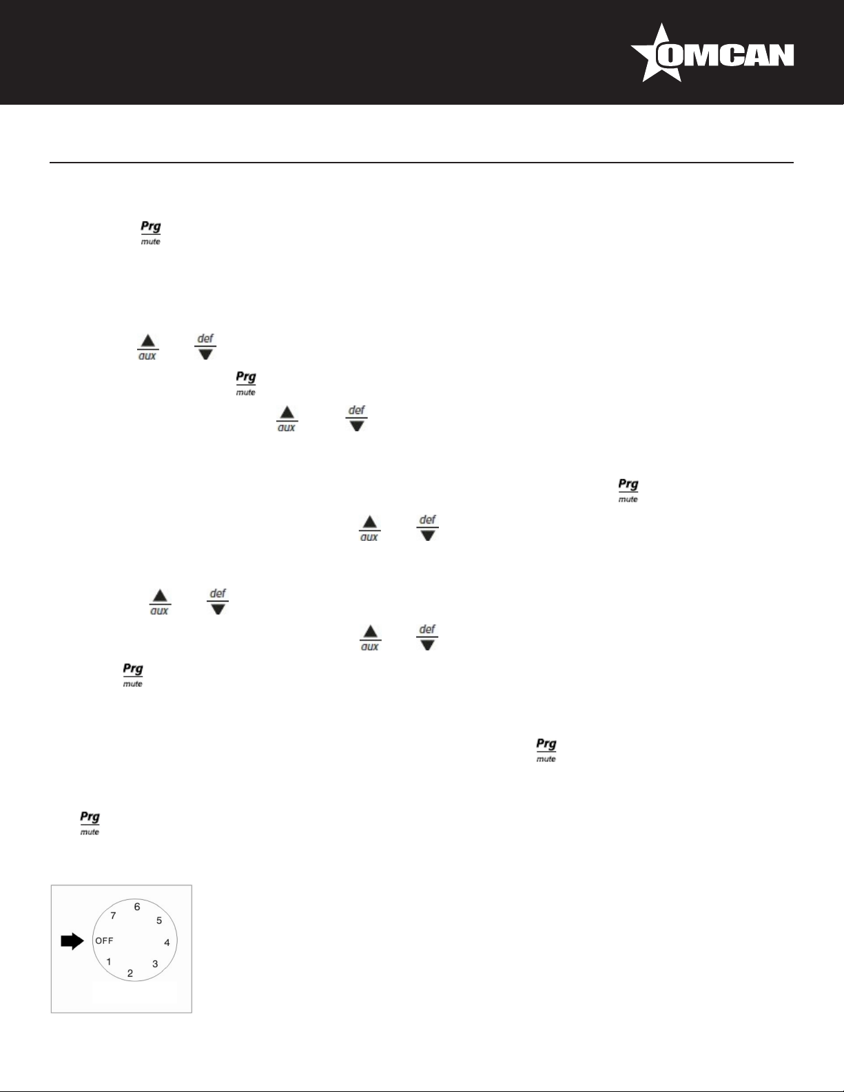
Controller Instructions
Digital controller model: PJEZ for cooler
Display and functions
During normal operation, the controller displays the value of the probe set using parameter/4(=1 ambient
probe, default, = 2 second probe, = 3 third probe).In addition, the display has LEDs that indicate the activation
of the control functions (see Table 1), while the 3 buttons can be used to activate/deactivate some of the
functions(see Table 2).
LED’s and Associated Functions (Table 1)
Icon Function Normal Operation Start Up
ON OFF Blink
Compressor On Off Request ON
Fan On Off Request ON
Defrost On Off Request ON
Aux Output On Output Off - ON
Alarm All No Alarm - ON
Clock RTC tted and enabled, at
least 1 time band set
RTC not tted or disabled, not
even 1 time band set
- ON if RTC
tted
10
Page 11
Controller Instructions
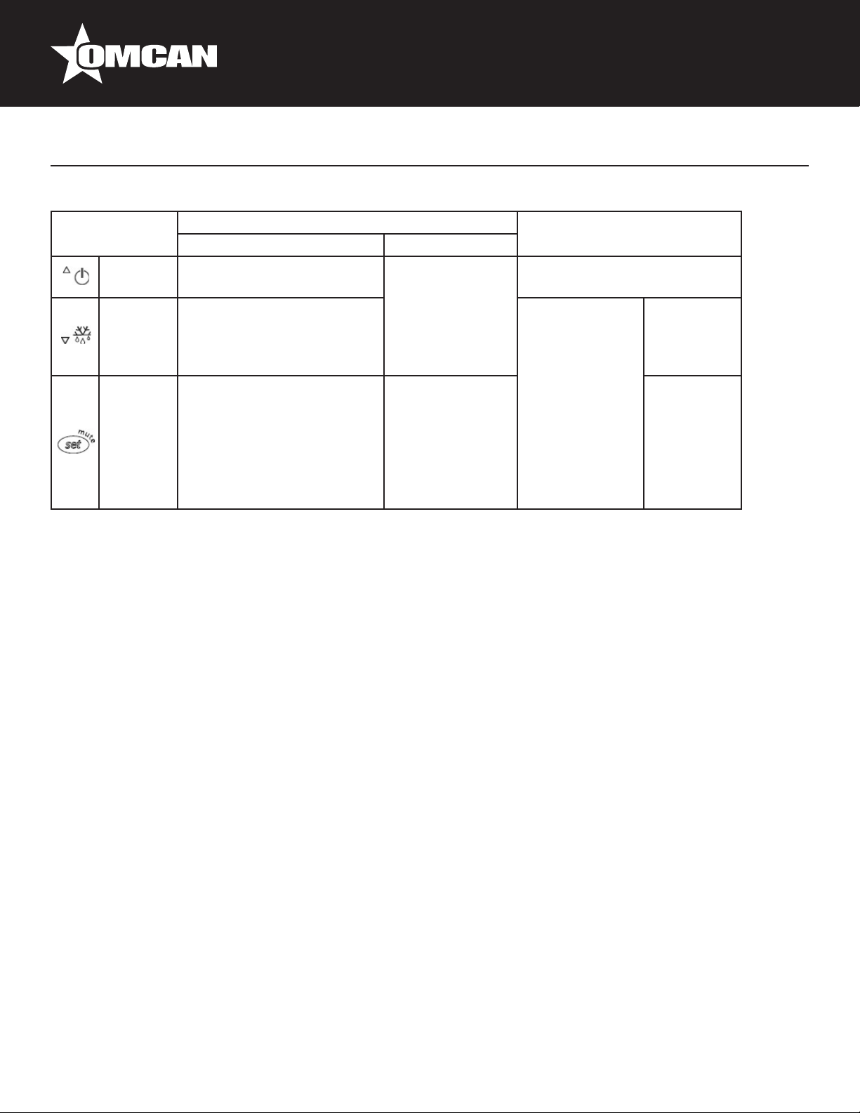
Table of Functions activated by the buttons - Models S, X, Y, C (Table 2)
Button Normal Operation Start Up
Pressing the Button Alone Pressed Together
Up
ON/OFF
Down
Defrost
Set Mute - 1 sec.: display/set the set
Setting the set point (desired temperature)
More than 3 sec: toggle ON/
OFF
More than 3 sec: start/stop
defrost
point.
- more than 3 secs.: access
parameter setting menu
(enter password )
- mute audible alarm
(buzzer)
Start/Stop
continuous cycle
- For 1 sec.
-
Pressed
together
Start parameter
reset procedure
For 1 sec.
display
rmware
vers. code
RESET current EZY set
• press SET for 1 sec, the set value will start ashing after a few moments;
• increase or decrease the value using UP or DOWN;
• press SET to conrm the new value.
Switching the device ON/OFF
Press UP for more than 3 sec. The control and defrost algorithms are now disabled and the Instrument
displays the message “OFF” alternating with the temperature read by the set probe.
Manual defrost
Press for DOWN more than 3 sec (the defrost starts only the temperature conditions are valid).
Continuous cycle
Press UP and DOWN together for more than 3 sec.
Access and setting type F (frequent) and type C (conguration) parameters.
1. Press SET for 3 sec (the display will show “PS”).
2. • To access the type F and C parameter menu, enter the password “22” using UP/DOWN, press SET to
conrm.
• To access the F parameter menu only, press SET (without entering the password).
3. Scroll inside the parameter menu using UP/DOWN.
11
Page 12
Controller Instructions
• To display/set the values of the parameter displayed, press SET, then UP/DOWN and nally SET to
conrm the changes (returning to the parameter menu).
To save all the new values and exit the parameter menu, press SET for 3 s.
To exit the menu without saving the changed values (exit by timeout) do not press any button for at least 60 s.
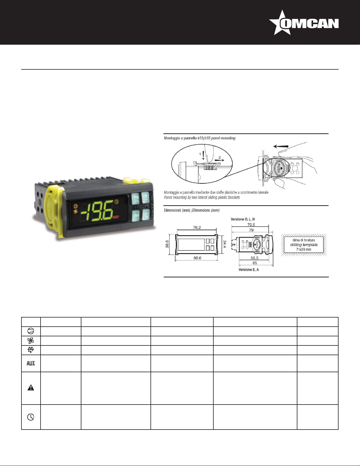
Digital controller model: IR33 for freezer
Signals on the display
The blinking status indicates a request for activation that cannot be implemented until the end of the
Corresponding delay times.
Icon Function ON OFF Blink Startup
Compressor Compressor on Compressor off Request
Fan Fan on Fan off Request
Defrost Defrost in progress Defrost not required Request
Aux Auxiliary Output AUX
active
Alarm Delayed external
alarm (before the
expiry of the time ‘A7’)
Clock At least one timed
defrost has been set
Auxiliary Output
AUX not active
No alarm present Alarms in normal operation
No timed defrost is
present
Anti-sweat heater function
active
(eg. high/low temp.) or
alarm from ext. digital input
immediate or delayed
Clock alarm On if Real-
Time Clock
present
12
Page 13
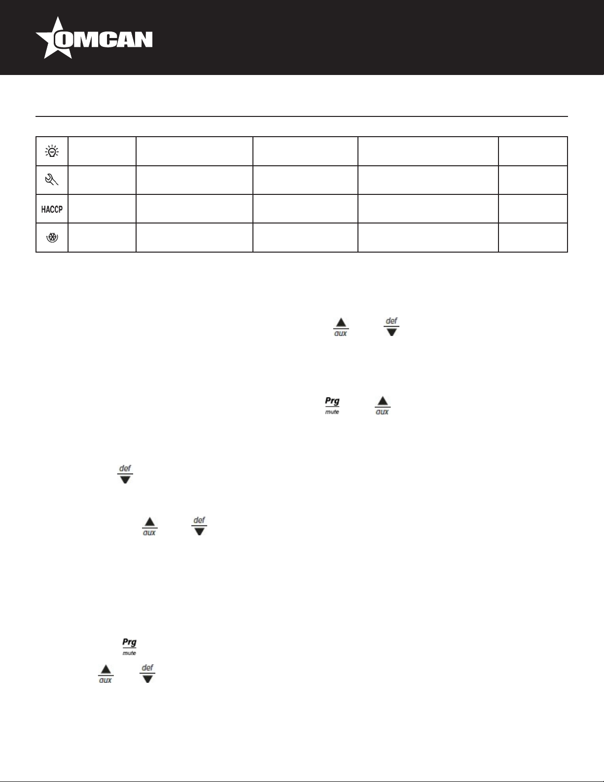
Controller Instructions
Light Auxiliary output light
active
Service No malfunction Malfunction (eg. EEPROM
HACCP HACCP function HACCP function
Continuous
Cycle
Enabled Not enabled Request
Auxiliary output light
not active
enabled
Anti-sweat heater function
active
error or probe fault)
HACCP alarm (HA and/or
HF) not enabled
Setting the set point (desired temperature value)
To display or set the set point, proceed as follow:
1. press the “Set” button for more than 1 second to display the set point;
2. increase or decrease the value of the set point, using the “ ” and “ ” respectively, until reaching the
desired value;
3. press the “Set” button again to conrm the new value,
Alarms with manual reset
The alarms with manual reset can be reset by pressing the “ ” and “ ” for more than 5 sec.
Manual defrost
As well as the automatic defrost function, a manual defrost can be enabled, if the temperature conditions allow,
by pressing the “ ” button for more than 5 sec.
Continuous cycle
Pressing the buttons “ ” and “ ” simultaneously for more than 5 seconds enables the continuous cycle
function. During operation in continuous cycle, the compressor continues to operate for the time “cc” and
it stops when it reaches the “cc” time out or the minimum temperature has been reached(AL = minimum
temperature alarm threshold). Continuous cycle setting: “cc” parameter (continuous cycle duration): “cc”=0
never active; “c6” parameter (by passing the alarm after the continuous cycle):”cc” = 0 never active; it avoid or
delays the low temperature alarm after the continuous cycle.
Accessing the conguration parameter (type C)
1. Pressing the “ ” and “Set” buttons at the same time for more than 5 sec, the display will show
“00”(password prompt).
2. Use the “ ” or “ ” buttons to display the number “22” (parameter access password).
3. Conrm by pressing “Set”.
4. The display will show the rst modiable “C” parameter.
13
Page 14
Controller Instructions
Accessing the conguration parameter (type F)
1. Hold the “ ” button for more than 5 s (if there are active alarms, rst mute the buzzer), the display will
show the rst modiable “F” parameter.
Modifying the parameters
After having displayed the parameter, either type “C” or type “F”, proceed as follows:
1. Use the “ ” or “ ” buttons to scroll the parameters, until reaching the parameter to be modied; when
scrolling the parameters, an icon is shown on the display that represents the category of the parameter.
2. Alternatively, press the “ ” button to display a menu that can be used to quickly access the family of
parameters to be modied.
3. Scrolling the menu using the “ ” and “ ” buttons displays the codes of the various categories of
parameter, accompanied by the corresponding icon on the display(if present).
4. Once having reached the desired category, press “Set” to go directly to the rst parameter in the chosen
category(if no parameter is visible, pressing the “Set” button will have no effect).
5. At this stage, modify the parameters or return to the “Category” menu, using the “ ” button.
6. Press “Set” to display the value associated with the parameter.
7. Increase or decrease the value using the “ ” or “ ” buttons respectively.
8. Press “Set” to temporarily save the new value and return to the display of the parameter.
9. Repeat the operation from point 1 or point 2.
10. If the parameter has sub-parameters, press “Set” to display the rst sub-parameter.
11. Press the “ ” or “ ” button to display all the sub-parameters.
12. Press “Set” to display the associated value.
13. Increase or decrease the value using the “ ” or “ ” button respectively.
14. Press “Set” to temporarily save the new value and return to the display of the sub-parameter code.
15. Press “ ” to return to the display of the parent parameter.
Saving the new values assigned to the parameters
To denitely save the new values of the modied parameters, press the “ ” button for more than 5 seconds,
thus exiting the parameter setting procedure. All the modication made to the parameters temporarily saved in
the RAM, can be cancelled and “normal operation” resumed by not pressing any button for 60 seconds, thus
allowing the parameter setting session to expire due to timeout if the Instrument is switched off before pressing
the “ ” button, all the modications made to the parameters and temporarily saved will be lost.
Mechanical Controller Instructions
OFF: shut the compressor off
Temperature range from 7 (coldest) to 1 (warmest).
CAUTION: Setting the temperature control to the coldest setting may cause the
evaporator coil to freeze and ice up. This will eventually result in a warmer cabinet
temperature.
14
Page 15

REFERENCE
Controller Instructions
Item Number Model Number Description
50032 RE-CN-0045-HC
50033 RE-CN-0009-HC
50035 RE-CN-0014-H
50036 RE-CN-0023-HC
50037 RE-CN-0023-H
50052 RE-CN-0052-HC
50029 FR-CN-0012-HC
50030 FR-CN-0790-HC
50031 FR-CN-1250-HC
38025 FR-CN-1250-C
50075 FR-CN-0045-HC
Refrigerator 2 Door Glass 44.8 cu.ft.
110V/60/1 cETLus/ETL Sanitation
Refrigerator 1 Door Glass 9.1 cu.ft.
110V/60/1 cETLus/ETL Sanitation
Refrigerated 1 Door Glass Merchandiser
14 cu.ft. cETLus/ETL Sanitation
Refrigerator 1 Door Glass 22.8 cu.ft.
110V/60/1 cETLus/ETL Sanitation
Refrigerator 1 Door Glass 22.8 cu.ft.
110V/60/1 Black Color with 5 Shelves
cETLus/ETL Sanitation
Refrigerator 3 Door Glass 52.3 cu.ft.
110V/60/1 cETLus/ETL Sanitation
Freezer 1 Door Glass Merchandiser White
12.3 cu.ft. 110V/60/1
cETLus/ETL Sanitation
Freezer Glass Door Single Door 31” /
790mm 110V/60/1 cETLus/ETL Sanitation
Freezer Glass Door Dual Door D Breaker
49” / 1250mm 110V/60/1 cETLus/ETL
Sanitation
Freezer Glass Door Dual Door Crankcase
Regulator 49” / 1250mm 110V/60/1 ETL
cETLus
Freezer 2 Door Glass 44.8 cu.ft. 115V/60/1
cETLus/ETL Sanitation
Manufacturer Model
Number
G1.2YBM2F-HC
G258BMF-HC
G398BMF-HC
G648BMF-HC
G648BMF-BL-HC
SG1.9L3-HC
D368BMF-HC
D648BMF-HC
D768BM2F-HC
D768BM2F-CPR
D1.2BM2F-HC
15
Page 16

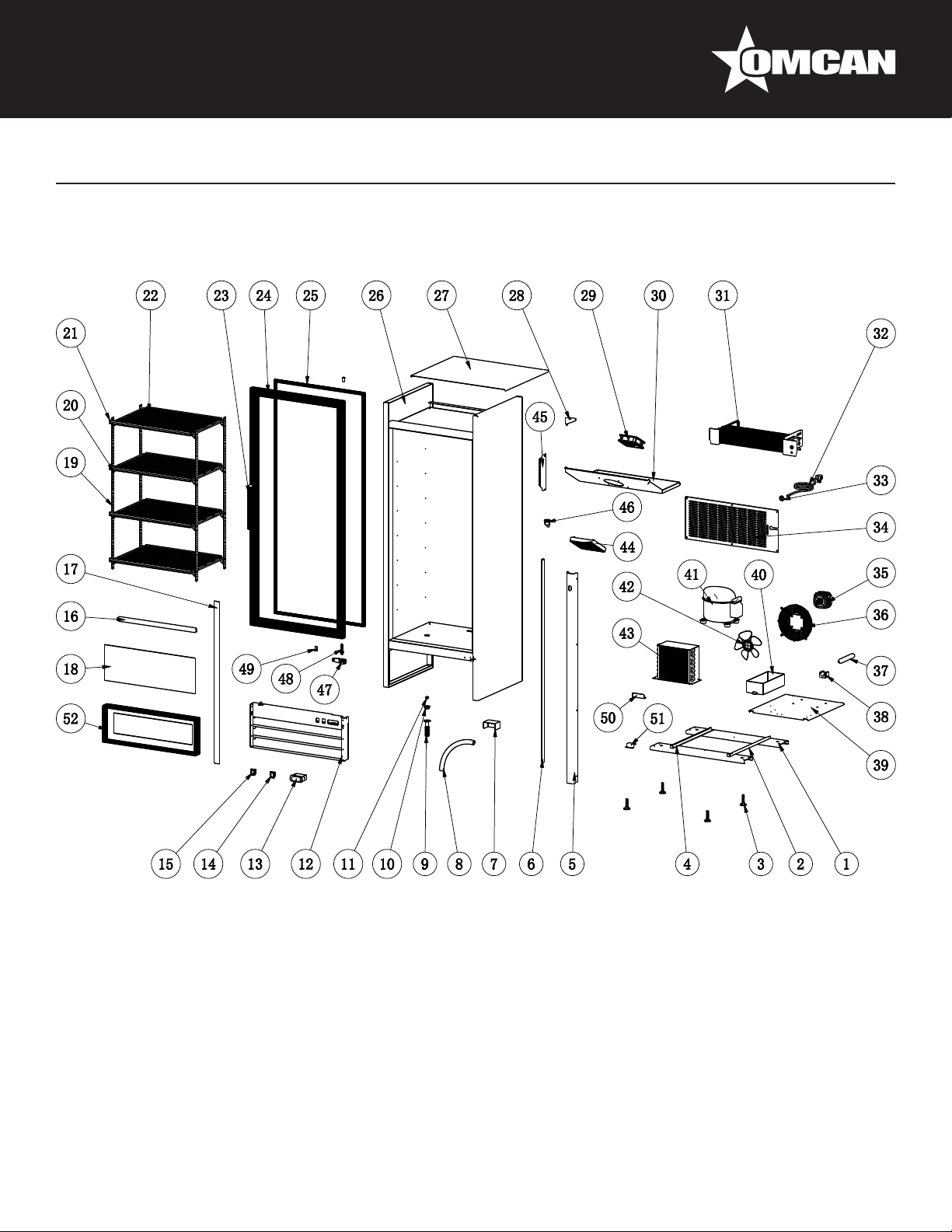
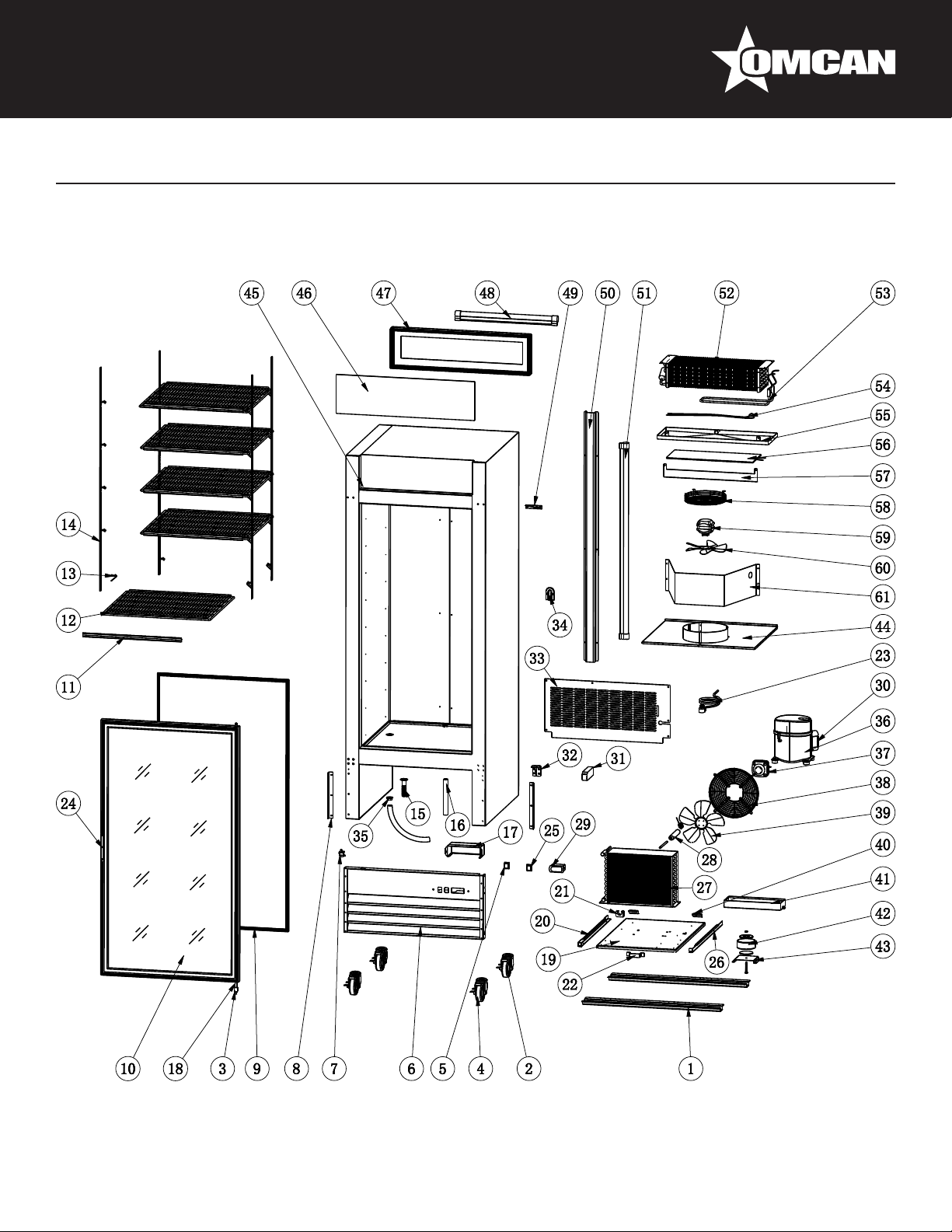
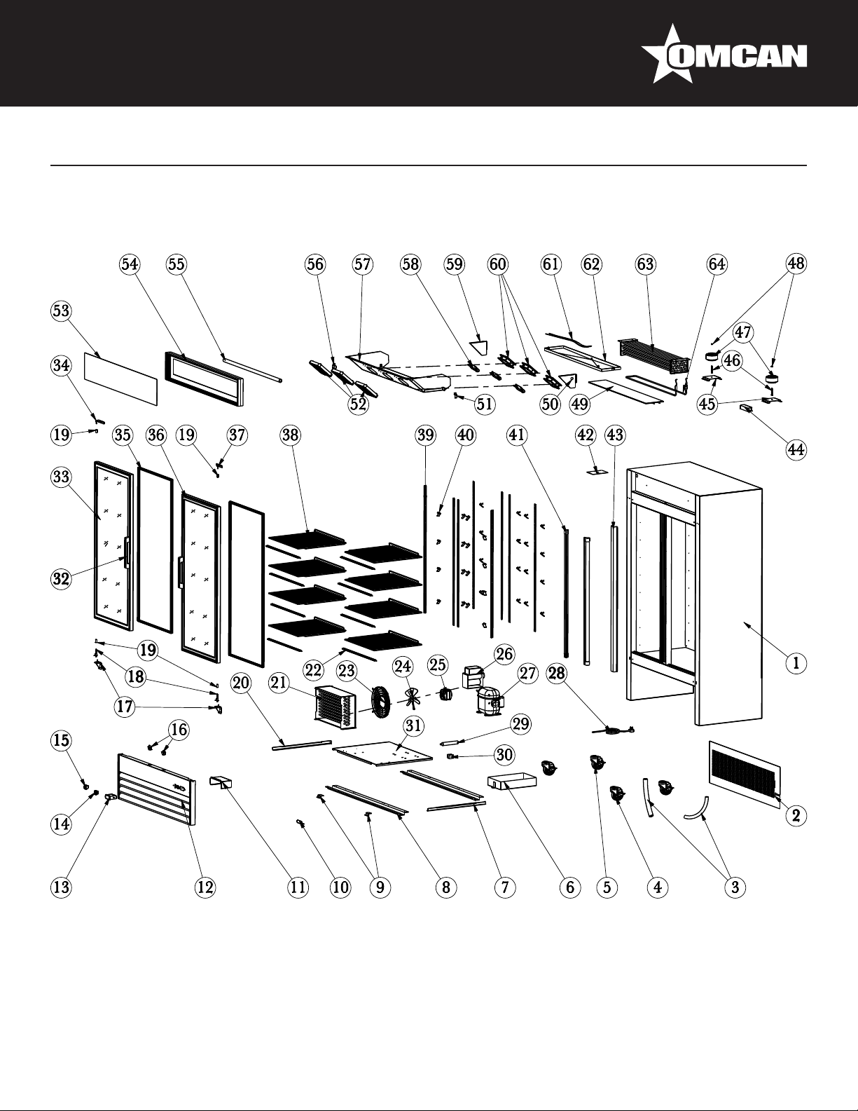
Parts Breakdown
Model RE-CN-0045-HC 50032
16
Page 17
Parts Breakdown
Model RE-CN-0045-HC 50032
Item No. Description Position Item No. Description Position Item No. Description Position
AA766 Left Glass Door for G1.2YBM2F-HC 1 AA385 K Clip for G1.2YBM2F-HC 23 AA710
AA767 Front Grill Fixer for G1.2YBM2F-HC 2 AA778 K Strip for G1.2YBM2F-HC 24 AA795
AA703 Power Cord Cover for G1.2YBM2F-HC 3 AA779 Shelf for G1.2YBM2F-HC 25 AA129 Filter Fixer for G1.2YBM2F-HC 47
AA768
64168 Compressor for G1.2YBM2F-HC 5 AA781 Light Box for G1.2YBM2F-HC 27 AA528 Drain Tube for G1.2YBM2F-HC 49
AA247
AA764
AA769
AA770 Condenser for G1.2YBM2F-HC 9 AA784
AA362 LED Switch for G1.2YBM2F-HC 10 AA785
AA124 Power Switch for G1.2YBM2F-HC 11 AA786 Cabinet for G1.2YBM2F-HC 33 AA800 Right Glass Door for G1.2YBM2F-HC 55
AA771 Caster Supporter for G1.2YBM2F-HC 12 AA787 LED Power Supply for G1.2YBM2F-HC 34 AA801
AA772
AA773
AA774 Support Rod for G1.2YBM2F-HC 15 AA790
AA123 Thermostat for G1.2YBM2F-HC 16 AA791 Evaporator for G1.2YBM2F-HC 38 AA804
AA743 Caster without Brake for G1.2YBM2F-HC 17 AA757
AA584 Caster with Brake for G1.2YBM2F-HC 18 AA792
AA775 Back Grill for G1.2YBM2F-HC 19 AA793
AA214
AA776 Front Grill for G1.2YBM2F-HC 21 68809
AA777 Shelf Tag for G1.2YBM2F-HC 22 61219
Compressor Component for G1.2YBM2FHC
Condenser Fan Motor for G1.2YBM2FHC
Condenser Fan Motor Blade for
G1.2YBM2F-HC
Condenser Fan Cover for G1.2YBM2FHC
Handle for Installation Board for
G1.2YBM2F-HC
Limit Block for Installation Board for
G1.2YBM2F-HC
Waterproof Cover of Thermostat for
G1.2YBM2F-HC
4 AA780 Light Plate for G1.2YBM2F-HC 26 AA130 Filter for G1.2YBM2F-HC 48
6 AA722 LED Light for G1.2YBM2F-HC 28 AA712 Drain Connector for G1.2YBM2F-HC 50
7 AA782
8 AA783 Outer Drain Pan for G1.2YBM2F-HC 30 AA797
13
14 AA789 Evaporator Cover for G1.2YBM2F-HC 36 AA803 Door Track for G1.2YBM2F-HC 58
20 AA794 Power Cord Cover for G1.2YBM2F-HC 42 AA687 Drain Plug for G1.2YBM2F-HC 64
AA788
LED Light in Light Box for G1.2YBM2FHC
Left Track for Installation Board for
G1.2YBM2F-HC
Compressor Unit Installation Board for
G1.2YBM2F-HC
Left Bracket for Evaporator Fan Cover for
G1.2YBM2F-HC
Left End Plate for Evaporator for
G1.2YBM2F-HC
Evaporator Installation Bracket for
G1.2YBM2F-HC
Right End Plate for Evaporator for
G1.2YBM2F-HC
Right Bracket for Evaporator Fan Cover
for G1.2YBM2F-HC
Evaporator Fan Motor for G1.2YBM2FHC
Evaporator Fan Motor Blade for
G1.2YBM2F-HC
29 AA796
31 AA798 Seal Strip for G1.2YBM2F-HC 53
32 AA799
35 AA802
37 AA191 Door Handle for G1.2YBM2F-HC 59
39 AA805 Power Cord for G1.2YBM2F-HC 61
40 AA806 Grill Fixer for G1.2YBM2F-HC 62
41 AA216 Drain Pipe for G1.2YBM2F-HC 63
43 AA686 Plastic Drain Tube for G1.2YBM2F-HC 65
44
Evaporator Fan Cover for G1.2YBM2FHC
Right Track for Installation Board for
G1.2YBM2F-HC
Upper or Bottom Cabinet Frame for
G1.2YBM2F-HC
Rubber Limited Block for G1.2YBM2FHC
Left or Right Cabinet Frame for
G1.2YBM2F-HC
Bigger Wheel for Door for G1.2YBM2FHC
Smaller Wheel for Door for G1.2YBM2FHC
Air Pipe Protection Board for
G1.2YBM2F-HC
45
46
51
52
54
56
57
60
17
Page 18

Parts Breakdown
Model RE-CN-0009-HC 50033
18
Page 19
Parts Breakdown
Model RE-CN-0009-HC 50033
Item No. Description Position Item No. Description Position Item No. Description Position
AA682 Castor Supporter for G258BMF-HC 1 AA691
AA683
AA185 Leveling Feet for G258BMF-HC 3 AA385 K Clip for G258BMF-HC 20 AA706
AA684
AA685 Back Plate for G258BMF-HC 5 AA694 Shelf for G258BMF-HC 22 AA129 Filter Fixer for G258BMF-HC 38
AA528 Inner Drain Tube for G258BMF-HC 6 AA695 Glass Door Handle for G258BMF-HC 23 AA707
AA214
AA216 Outer Drain Tube for G258BMF-HC 8 AA697 Glass Door Gasket for G258BMF-HC 25 64167 Compressor for G258BMF-HC 41
AA686
AA687 Drain Pipe Cover for G258BMF-HC 11 AA699 Upper Hinge for G258BMF-HC 27 AA709 Condenser for G258BMF-HC 43
AA688 Front Grill for G258BMF-HC 12 AA700
AA123 Thermostat for G258BMF-HC 13 AA128 Evaporator Fan Motor for G258BMF-HC 29 AA711 LED Power Supply for G258BMF-HC 45
AA362 LED Switch for G258BMF-HC 14 AA701 Evaporator Cover for G258BMF-HC 30 AA712
AA124 Power Switch for G258BMF-HC 15 AA702 Evaporator for G258BMF-HC 31 AA713 Bottom Hinge for G258BMF-HC 47
AA689 Upper Hinge Cover for G258BMF-HC 16 AA135 Power Cord for G258BMF-HC 32 AA714 Hinge Axis for G258BMF-HC 48
AA690 LED Light for G258BMF-HC 17 AA703 Power Cord Cover for G258BMF-HC 33 AA715 Axis Cover for G258BMF-HC 49
Right Track for Installation Board for
G258BMF-HC
Left Track for Installation Board for
G258BMF-HC
Waterproof Cover of Thermostat for
G258BMF-HC
Plastic Drain Pipe with Fixer for
G258BMF-HC
2 AA692 K Strip for G258BMF-HC 19 AA705 Condenser Fan Motor for G258BMF-HC 35
4 AA693 Shelf Tag for G258BMF-HC 21 AA130 Filter for G258BMF-HC 37
7 AA696 Glass Door for G258BMF-HC 24 AA708 Outer Drain Pan for G258BMF-HC 40
9, 10 AA698 Cabinet for G258BMF-HC 26 AA208
Handle of Installation Board for
G258BMF-HC
Complete Installation Board Limited Block
for G258BMF-HC
18 AA704 Back Grill for G258BMF-HC 34
Condenser Fan Motor Cover for
G258BMF-HC
Compressor Unit Installation Board for
G258BMF-HC
Condenser Fan Motor Blade for
G258BMF-HC
28 AA710
Evaporator Fan Motor Cover for
G258BMF-HC
Inner Drain Tube Connector for
G258BMF-HC
36
39
42
44
46
19
Page 20
Parts Breakdown
Model RE-CN-0014-H 50035
20
Page 21

Parts Breakdown
Model RE-CN-0014-H 50035
Item No. Description Position Item No. Description Position Item No. Description Position
AA716 Castor Supporter for G398BMF-HC 1 AA724 K Strip for G398BMF-HC 19 AA735
AA717
AA185 Leveling Feet for G398BMF-HC 3 AA725 Shelf Tag for G398BMF-HC 21 AA129 Filter Fixer for G398BMF-HC 38
AA718
AA719
AA528 Inner Drain Tube for G398BMF-HC 6 AA727 Glass Door for G398BMF-HC 24 64167 Compressor for G398BMF-HC 41
AA214
AA216 Outer Drain Tube for G398BMF-HC 8 AA729 Cabinet for G398BMF-HC 26 AA709 Condenser for G398BMF-HC 43
AA686
AA687 Drain Pipe Cover for G398BMF-HC 11 AA731 Upper Hinge for G398BMF-HC 28 AA711 LED Power Supply for G398BMF-HC 45
AA720 Front Grill for G398BMF-HC 12 AA128 Evaporator Fan Motor for G398BMF-HC 29 AA712
AA123 Thermostat for G398BMF-HC 13 AA732 Evaporator Cover for G398BMF-HC 30 AA713 Bottom Hinge for G398BMF-HC 47
AA362 LED Switch for G398BMF-HC 14 AA733 Evaporator for G398BMF-HC 31 AA714
AA124 Power Switch for G398BMF-HC 15 AA135 Power Cord for G398BMF-HC 32 AA715 Axis Cover for G398BMF-HC 49
AA721 LED in Light Box for G398BMF-HC 16 AA703 Power Cord Cover for G398BMF-HC 33 AA738
AA722 LED Light for G398BMF-HC 17 AA734 Back Grill for G398BMF-HC 34 AA739
AA723
Right Track for Installation Board for
G398BMF-HC
Left Track for Installation Board for
G398BMF-HC
Air Pipe Protection Board for G398BMFHC
Waterproof Cover of Thermostat for
G398BMF-HC
Plastic Drain Pipe with Fixer for
G398BMF-HC
Handle of Installation Board for
G398BMF-HC
2 AA385 K Clip for G398BMF-HC 20 AA130 Filter for G398BMF-HC 37
4 AA726 Shelf for G398BMF-HC 22 AA736
5 AA695 Glass Door Handle for G398BMF-HC 23 AA737 Outer Drain Pan for G398BMF-HC 40
7 AA728 Glass Door Gasket for G398BMF-HC 25 AA208
9, 10 AA730 Top Cover for G398BMF-HC 27 AA710
18 AA705 Condenser Fan Motor for G398BMF-HC 35 AA740 Light Box Frame for G398BMF-HC 52
Condenser Fan Motor Cover for
G398BMF-HC
Compressor Unit Installation Board for
G398BMF-HC
Condenser Fan Motor Blade for
G398BMF-HC
Evaporator Fan Motor Cover for
G398BMF-HC
Inner Drain Tube Connector for
G398BMF-HC
Hinge Axis for G398BMF-HC 48
Handle of Installation Board for
G398BMF-HC
Limit Block for Installation Board for
G398BMF-HC
36
39
42
44
46
50
51
21
Page 22

Parts Breakdown
Model RE-CN-0023-HC 50036
22
Page 23

Parts Breakdown
Model RE-CN-0023-HC 50036
Item No. Description Position Item No. Description Position Item No. Description Position
AA741
AA742 Castor Supporter for G648BMF-HC 2 AA749 Cabinet for G648BMF-HC 21 AA710 Evaporator Fan Cover for G648BMF-HC 39
AA135 Power Cord for G648BMF-HC 3 AA750 Outer Drain Pan for G648BMF-HC 22 AA712
AA703 Power Cord Cover for G648BMF-HC 4 AA751
AA743
AA584 4” Caster with Brake for G648BMF-HC 6 AA713 Bottom Hinge for G648BMF-HC 25 AA695 Glass Door Handle for G648BMF-HC 43
AA744 Back Grill for G648BMF-HC 7 AA714 Hinge Axis for G648BMF-HC 26 AA731 Upper Hinge for G648BMF-HC 44
AA216 Outer Drain Tube for G648BMF-HC 8 AA715 Axis Cover for G648BMF-HC 27 AA761 Glass Door for G648BMF-HC 45
AA687 Drain Plug for G648BMF-HC 9 AA753 Light Box Plate for G648BMF-HC 28 AA762 Gasket for G648BMF-HC 46
AA686
AA123 Thermostat for G648BMF-HC 12 AA721 LED in Light Box for G648BMF-HC 30 AA763
AA362 LED Switch for G648BMF-HC 13 AA711 LED Power Supply for G648BMF-HC 31 AA247 Condenser Fan Motor for G648BMF-HC 49
AA124 Power Switch for G648BMF-HC 14 AA755
AA745 Front Grill for G648BMF-HC 15 AA756 Evaporator Cover for G648BMF-HC 33 AA130 Filter for G648BMF-HC 51
AA746 K Strip for G648BMF-HC 16 61219
AA385 K Clip for G648BMF-HC 17 AA757
AA747 Shelf for G648BMF-HC 18 68809 Evaporator Fan Motor for G648BMF-HC 36 AA250 Condenser for G648BMF-HC 54
AA748 Shelf Tag for G648BMF-HC 19 AA758
Right Track for Installation Board for
G648BMF-HC
4” Caster without Brake for G648BMFHC
Drain Tube Fixer with Plastic Drain Pipe
for G648BMF-HC
1 AA722 LED Light for G648BMF-HC 20 AA759 Evaporator for G648BMF-HC 38
Inner Drain Tube Connector for
G648BMF-HC
Left Track for Installation Board for
G648BMF-HC
5 AA752
10, 11 AA754 Light Box Frame for G648BMF-HC 29 64167 Compressor for G648BMF-HC 47
Compressor Unit Installation Board for
G648BMF-HC
Left Bracket for Evaporator Fan Cover for
G648BMF-HC
Evaporator Fan Motor Blade for
G648BMF-HC
Evaporator Fan Motor Bracket for
G648BMF-HC
Right Bracket for Evaporator Fan Cover
for G648BMF-HC
23 AA528 Outer Drain Tube for G648BMF-HC 41
24 AA760
32 AA764
34 AA129 Filter Fixer for G648BMF-HC 52
35 AA765
37
Air Pipe Protection Board for G648BMFHC
Compressor Component for G648BMFHC
Condenser Fan Motor Blade for
G648BMF-HC
Condenser Fan Motor Cover for
G648BMF-HC
40
42
48
50
53
23
Page 24

Parts Breakdown
Model RE-CN-0023-H 50037
24
Page 25

Parts Breakdown
Model RE-CN-0023-H 50037
Item No. Description Position Item No. Description Position Item No. Description Position
AB953
AB954 Castor Supporter for G648BMF-BL-HC 2 AA722 LED Light for G648BMF-BL-HC 20 AA759 Evaporator for G648BMF-BL-HC 38
AA135 Power Cord for G648BMF-BL-HC 3 AB958 Cabinet for G648BMF-BL-HC 21 AA710
AA703 Power Cord Cover for G648BMF-BL-HC 4 AB959 Outer Drain Pan for G648BMF-BL-HC 22 AA712
AA743
AA584
AB955 Back Grill for G648BMF-BL-HC 7 AA713 Bottom Hinge for G648BMF-BL-HC 25 AA695 Glass Door Handle for G648BMF-BL-HC 43
AA216 Outer Drain Tube for G648BMF-BL-HC 8 AA714 Hinge Axis for G648BMF-BL-HC 26 AB966 Upper Hinge for G648BMF-BL-HC 44
AA687 Drain Plug for G648BMF-BL-HC 9 AA715 Axis Cover for G648BMF-BL-HC 27 AA761 Glass Door for G648BMF-BL-HC 45
AA686 Drain Tube Fixer for G648BMF-BL-HC 10 AA753 Light Box Plate for G648BMF-BL-HC 28 AA762 Gasket for G648BMF-BL-HC 46
AA686 Plastic Drain Pipe for G648BMF-BL-HC 11 AA754 Light Box Frame for G648BMF-BL-HC 29 64167 Compressor for G648BMF-BL-HC 47
AA123 Thermostat for G648BMF-BL-HC 12 AA721 LED in Light Box for G648BMF-BL-HC 30 AB967
AA362 LED Switch for G648BMF-BL-HC 13 AA711 LED Power Supply for G648BMF-BL-HC 31 AA247
AA124 Power Switch for G648BMF-BL-HC 14 AB962
AB956 Front Grill for G648BMF-BL-HC 15 AB963 Evaporator Cover for G648BMF-BL-HC 33 AB594 Filter for G648BMF-BL-HC 51
AB957 K Strip for G648BMF-BL-HC 16 61219
AA385 K Clip for G648BMF-BL-HC 17 AA757
AA747 Shelf for G648BMF-BL-HC 18 68809
Right Track for Installation Board for
G648BMF-BL-HC
4” Castor without Brake for G648BMFBL-HC
4” Castor with Brake for G648BMFBL-HC
1 AA748 Shelf Tag for G648BMF-BL-HC 19 AB964
5 AB960
6 AB961
Left Track for Installation Board for
G648BMF-BL-HC
Compressor Unit Installation Board for
G648BMF-BL-HC
Left Bracket for Evaporator Fan Cover for
G648BMF-BL-HC
Evaporator Fan Motor Blade for
G648BMF-BL-HC
Evaporator Fan Motor Bracket for
G648BMF-BL-HC
Evaporator Fan Motor for G648BMFBL-HC
23 AA528 Outer Drain Tube for G648BMF-BL-HC 41
24 AB965
32 AA764
34 AB595 Filter Fixer for G648BMF-BL-HC 52
35 AA249
36 AA250 Condenser for G648BMF-BL-HC 54
Right Bracket for Evaporator Fan Cover
for G648BMF-BL-HC
Evaporator Fan Cover for G648BMFBL-HC
Inner Drain Tube Connector for
G648BMF-BL-HC
Air Pipe Protection Board for G648BMFBL-HC
Compressor Component for G648BMFBL-HC
Condenser Fan Motor for G648BMFBL-HC
Condenser Fan Motor Blade for
G648BMF-BL-HC
Condenser Fan Motor Cover for
G648BMF-BL-HC
37
39
40
42
48
49
50
53
25
Page 26

Parts Breakdown
Model RE-CN-0052-HC 50052
26
Page 27
Parts Breakdown
Model RE-CN-0052-HC 50052
Item No. Description Position Item No. Description Position Item No. Description Position
61219 Evaporator Fan Blade for SG1.9L3-HC 1 AA820
68809 Evaporator Fan Motor for SG1.9L3-HC 2 AA715 Plastic Axis Cover for SG1.9L3-HC 23 AA837 Light Box Plate for SG1.9L3-HC 44
AA807 Right Bottom Hinge for SG1.9L3-HC 3 AA821 Outer Drain Pan for SG1.9L3-HC 24 AA695 Glass Door Handle for SG1.9L3-HC 45
AA808 Left Bottom Hinge for SG1.9L3-HC 4 AA822 Outer Drain Pan Fixer for SG1.9L3-HC 25 AA838
AA385 K Clip for SG1.9L3-HC 5 AA823 Installation Board for SG1.9L3-HC 26 AA839
AA809 K Strip for SG1.9L3-HC 6 AA824
64170 Compressor for SG1.9L3-HC 7 AA825
AA687 Drain Pipe Plug for SG1.9L3-HC 8 AA826
AA810 Bottom Hinge Axis for SG1.9L3-HC 9 AA827
AA811 Middle Shelf for SG1.9L3-HC 10 AA828 Left Upper Hinge for SG1.9L3-HC 31 AA216 Drain Tube for SG1.9L3-HC 52
AA812 Inner Drain Pan for SG1.9L3-HC 11 AA829 Left Shelf for SG1.9L3-HC 32 AA130 Filter for SG1.9L3-HC 53
AA300 Condenser for SG1.9L3-HC 12 AA830 Left Glass Door for SG1.9L3-HC 33 AA129 Filter Fixer for SG1.9L3-HC 54
AA813 Condenser Fan Motor for SG1.9L3-HC 13 AA686 Plastic Drain Hose for SG1.9L3-HC 34 AA787 LED Power Supply for SG1.9L3-HC 55
AA814
AA815
AA584 Front Caster with Brake for SG1.9L3-HC 16 AA833
AA816 Cabinet for SG1.9L3-HC 17 AA123 Thermostat for SG1.9L3-HC 38 AA757 Evaporator Fan Fixer for SG1.9L3-HC 59
AA817 Right Upper Hinge for SG1.9L3-HC 18 AA834 Fixer for Inner LED Light for SG1.9L3-HC 39 AA846
AA818 Right Shelf for SG1.9L3-HC 19 AA835 LED Inside Cabinet for SG1.9L3-HC 40 AA847
AA743
AA819 Back Grill for SG1.9L3-HC 21 AA722 LED Inside Light Box for SG1.9L3-HC 42
Condenser Fan Motor Blade for
SG1.9L3-HC
Condenser Fan Motor Cover for
SG1.9L3-HC
Back Caster without Brake for SG1.9L3HC
14 AA831 Supporting Board for SG1.9L3-HC 35 AA843 Gasket for SG1.9L3-HC 56
15 AA832
20 AA362 LED Switch for SG1.9L3-HC 41 AA710 Evaporator Fan Cover for SG1.9L3-HC 62
Air Pipe Protection Board for SG1.9L3HC
Right Track for Installation Board for
SG1.9L3-HC
Left Track for Installation Board for
SG1.9L3-HC
Installation Board Limited Block for
SG1.9L3-HC
Handle for Installation Board for
SG1.9L3-HC
Right Connecting Board for Caster for
SG1.9L3-HC
Left Connecting Board for Caster for
SG1.9L3-HC
22 AA836 Light Box Frame for SG1.9L3-HC 43
Thermostat Installation Plate for
SG1.9L3-HC
Waterproof Cover for Thermostat for
SG1.9L3-HC
27 AA124 Power Switch for SG1.9L3-HC 48
28 AA840 Front Grill for SG1.9L3-HC 49
29 AA841 Caster Supporter for SG1.9L3-HC 50
30 AA842 Evaporator for SG1.9L3-HC 51
36 AA844 Door Switch for SG1.9L3-HC 57
37 AA845 Evaporator Cover for SG1.9L3-HC 58
Right Bafe for Evaporator Fan Motor for
SG1.9L3-HC
Left Bafe for Evaporator Fan Motor for
SG1.9L3-HC
46
47
60
61
27
Page 28

Parts Breakdown
Model FR-CN-0012-HC 50029
28
Page 29

Parts Breakdown
Model FR-CN-0012-HC 50029
Item No. Description Position Item No. Description Position Item No. Description Position
AA848 Gasket for D368BMF-HC 1 AA857 Upper Hinge for D368BMF-HC 23 64174 Compressor for D368BMF-HC 44
AA807 Bottom Hinge for D368BMF-HC 2 AA858
AA810 Bottom Hinge Axis for D368BMF-HC 3 AA385 K Clip for D368BMF-HC 25 AA208 Condenser Fan Blade for D368BMF-HC 46
AA715 Axis Cover for D368BMF-HC 4 AA859 K Strip for D368BMF-HC 26 AA875
AA849 Glass Door for D368BMF-HC 5 AA860 Light Box Plate for D368BMF-HC 27 AA709 Condenser for D368BMF-HC 48
AA850 Water Proof Cover for D368BMF-HC 6 AA861 Light Box Frame for D368BMF-HC 28 AA876
AA851 Front Grill for D368BMF-HC 7 AA862 Cabinet LED for D368BMF-HC 29 AA877
AA852 Back Grill for D368BMF-HC 8 AA863 Fixer for Probe for D368BMF-HC 30 AA878
AA743 Castor for D368BMF-HC 9 AA864 Drain Pan Heater for D368BMF-HC 31 AA879
AA584 Castor with Brake for D368BMF-HC 10 AA865 Defrost Heater for D368BMF-HC 32 AA880
AA853 Shelf for D368BMF-HC 11 AA866 Evaporator Drain Pan for D368BMF-HC 33 AA881
AA124 Power Switch for D368BMF-HC 12 AA867 Drain Hose Heater for D368BMF-HC 34 AA711 Power Supply for LED for D368BMF-HC 55
AA324 Thermostat for D368BMF-HC 13 AA868
AA854 Shelf Tag for D368BMF-HC 14 AA710
AA844 Door Switch for D368BMF-HC 15 AA869 Evaporator Cover for D368BMF-HC 37 AA129 Clip for Filter Drier for D368BMF-HC 58
AA686 Drain Hose for D368BMF-HC 16 AA870
AA687 Drain Plug for D368BMF-HC 17 AA128 Evaporator Fan Motor for D368BMF-HC 39 AA884
AA362 Light Switch for D368BMF-HC 18 AA871 Evaporator for D368BMF-HC 40 AA885 LED Light for D368BMF-HC 61
AA855 Cabinet for D368BMF-HC 19 AA872
AA216 Inner Drain Pipe for D368BMF-HC 20, 21 AA873
AA856 Power Cord for D368BMF-HC 22 AA874 Outer Drain Pan for D368BMF-HC 43
Installation Board Handle for D368BMFHC
Left Bracket for Evaporator Cover for
D368BMF-HC
Evaporator Fan Motor Cover for
D368BMF-HC
Left End Plate for Evaporator for
D368BMF-HC
Right End Plate for Evaporator for
D368BMF-HC
Right Bracket for Evaporator Cover for
D368BMF-HC
24 AA705 Condenser Fan Motor for D368BMF-HC 45
Condenser Fan Motor Cover for
D368BMF-HC
Compressor Installation Board for
D368BMF-HC
Right Track for Installation Board for
D368BMF-HC
Castor Installation Plate for D368BMFHC
Installation Board Block for D368BMFHC
Left Track for Installation Board for
D368BMF-HC
Compressor Component for D368BMFHC
35 AA882
36 AA883
38 AA130 Filter Drier for D368BMF-HC 59
41 AA695 Glass Door Handle for D368BMF-HC 62
42
Installation Board for Transformer for
D368BMF-HC
Transformer for Door Heater for
D368BMF-HC
Air Pipe Protection Board for D368BMFHC
47
49
50
51
52
53
54
56
57
60
29
Page 30
Parts Breakdown
Model FR-CN-0790-HC 50030
30
Page 31

Parts Breakdown
Model FR-CN-0790-HC 50030
Item No. Description Position Item No. Description Position Item No. Description Position
AA886
AA743 Castor for D648BMF-HC 2 AA856 Power Cord for D648BMF-HC 23 AA902
AA810 Hinge Axis for D648BMF-HC 3 AA695 Glass Door Handle for D648BMF-HC 24 AA903 Evaporator Cover for D648BMF-HC 44
AA584 Castor with Brake for D648BMF-HC 4 AA124 Power Switch for D648BMF-HC 25 AA904 Cabinet for D648BMF-HC 45
AA362 Light Switch for D648BMF-HC 5 AA895
AA887 Front Grill for D648BMF-HC 6 AA896 Condenser for D648BMF-HC 27 AA906 Light Box Frame for D648BMF-HC 47
AA844 Door Switch for D648BMF-HC 7 AA130 Filter Drier for D648BMF-HC 28 AA721 LED in Light Box for D648BMF-HC 48
AA888
AA843 Gasket for D648BMF-HC 9 AA897
AA889 Glass Door for D648BMF-HC 10 AA711 LED Power Supply for D648BMF-HC 31 AA722 LED Inside Cabinet for D648BMF-HC 51
AA748 Shelf Tag for D648BMF-HC 11 AA807 Bottom Hinge for D648BMF-HC 32 AA908 Evaporator for D648BMF-HC 52
AA747 Shelf for D648BMF-HC 12 AA898 Back Grill for D648BMF-HC 33 AA909 Defrost Heater for D648BMF-HC 53
AA385 K Clip for D648BMF-HC 13 AA863 Fixer for Probe for D648BMF-HC 34 AA867 Drain Hose Heater for D648BMF-HC 54
AA890 K Strip for D648BMF-HC 14 AA687 Drain Plug for D648BMF-HC 35 AA910 Evaporator Drain Pan for D648BMF-HC 55
AA216 Drain Pipe for D648BMF-HC 15, 16 64174 Compressor for D648BMF-HC 36 AA911 Drain Pan Heater for D648BMF-HC 56
AA891 Water Proof Cover for D648BMF-HC 17 AA813 Condenser Fan Motor for D648BMF-HC 37 AA912 Evaporator Bafe for D648BMF-HC 57
AA715 Axis Cover for D648BMF-HC 18 AA899
AA892
AA893
AA129 Clip for Filter Drier for D648BMF-HC 21 AA901 Outer Drain Pan for D648BMF-HC 41 AA914 Fan Motor Air Bafe for D648BMF-HC 61
Castor Installation Board for D648BMFHC
Fixed Strip for Front Grill for D648BMFHC
Compressor Installation Board for
D648BMF-HC
Left Track for Installation Board for
D648BMF-HC
1 AA894
8 AA324 Thermostat for D648BMF-HC 29 AA857 Upper Hinge for D648BMF-HC 49
19 AA814 Condenser Fan Blade for D648BMF-HC 39 AA913 Evaporator Fan Motor for D648BMF-HC 59
20 AA900
Handle for Installation Board for
D648BMF-HC
Right Track for Installation Board for
D648BMF-HC
Compressor Component for D648BMFHC
Condenser Fan Motor Cover for
D648BMF-HC
Installation Board Limited Block for
D648BMF-HC
22 AA883
26 AA905 Light Box Plate for D648BMF-HC 46
30 AA907
38 AA710
40 AA248
Glass Door Transformer for D648BMFHC
Transformer Installation Board for
D648BMF-HC
Air Pipe Protection Board for D648BMFHC
Evaporator Fan Motor Cover for
D648BMF-HC
Evaporator Fan Motor Blade for
D648BMF-HC
42
43
50
58
60
31
Page 32

Parts Breakdown
Model FR-CN-1250-HC 50031
Model FR-CN-1250-C 38025
32
Page 33

Parts Breakdown
Model FR-CN-1250-HC 50031
Model FR-CN-1250-C 38025
Item No. Description Position Item No. Description Position Item No. Description Position
AB968 Cabinet for D768BM2F-HC 1 AA810 Bottom Hinge Axis for D768BM2F-HC 20 AB985 Right Shelf for D768BM2F-HC 39
AA805 Power Cord for D768BM2F-HC 2 AA715 Axis Cover for D768BM2F-HC 21 AB957 K Strip for D768BM2F-HC 40
AA124 Power Switch for D768BM2F-HC 3 AB978
AB969 Back Grill for D768BM2F-HC 4 AA300 Condenser for D768BM2F-HC 23 AA722 LED Light for D768BM2F-HC 42
AA216 Drain Tube for D768BM2F-HC 5 AA249 Condenser Fan Cover for D768BM2F-HC 24 AB986
AA743 Castor without Brake for D768BM2F-HC 6 AA814
AA584 Castor with Brake for D768BM2F-HC 7 AB656 Condenser Fan Motor for D768BM2F-HC 26 AB987
AB970 Outer Drain Pan for D768BM2F-HC 8 AB979
AB971
AA695 Glass Door Handle for D768BM2F-HC 10 AA854 Shelf Tag for D768BM2F-HC 29 AB989 Light Box Plate for D768BM2F-HC 48
AB972 Castor Supporter for D768BM2F-HC 11 AB594 Filter for D768BM2F-HC 30 AB990 Light Box Frame for D768BM2F-HC 49
AB973
AB974
AB975
AB976 Front Grill for D768BM2F-HC 15 AA808 Upper Left Hinge for D768BM2F-HC 34 AB993
AA123 Thermostat for D768BM2F-HC 16 AB982 Gasket for D768BM2F-HC 35 AA128
AA362 LED Switch for D768BM2F-HC 17 AB983 Right Glass Door for D768BM2F-HC 36 AB994 Top Cover for D768BM2F-HC 55
AB977 Door Switch for D768BM2F-HC 18 AA857 Upper Right Hinge for D768BM2F-HC 37 AB995 Inner Drain Pan for D768BM2F-HC 56
AA807 Bottom Hinge for D768BM2F-HC 19 AB984 Left Shelf for D768BM2F-HC 38 AB996 Evaporator for D768BM2F-HC 57
Right Rail for Installation Board for
D768BM2F-HC
Limited Block for Installation Board for
D768BM2F-HC
Handle for Installation Board for
D768BM2F-HC
Waterproof Cover of Thermostat for
D768BM2F-HC
9 64168 Compressor for D768BM2F-HC 28 AA710
12 AB595 Filter Fixer for D768BM2F-HC 31 AA835
13 AB980
14 AB981 Left Glass Door for D768BM2F-HC 33 AB992 Evaporator Cover for D768BM2F-HC 52
Left Rail for Installation Board for
D768BM2F-HC
Condenser Fan Motor Blade for
D768BM2F-HC
Compressor Component for D768BM2FHC
Compressor Unit Installation Board for
D768BM2F-HC
22 AA385 K Clip for D768BM2F-HC 41
Air Pipe Protection Board for
D768BM2F-HC
25 AA787 LED Power Supply for D768BM2F-HC 44
Right End Plate for Evaporator for
D768BM2F-HC
27 AB988
32 AB991
Right Bracket for Evaporator Fan Cover
for D768BM2F-HC
Evaporator Fan Cover for D768BM2FHC
LED Light in Light Box for D768BM2FHC
Left Bracket for Evaporator Fan Cover
for D768BM2F-HC
Left End Plate for Evaporator for
D768BM2F-HC
Evaporator Fan Motor for D768BM2FHC
43
45
46
47
50
51
53
54
33
Page 34
Parts Breakdown
Model FR-CN-0045-HC 50075
34
Page 35

Parts Breakdown
Model FR-CN-0045-HC 50075
Item No. Description Position Item No. Description Position Item No. Description Position
AA915 Cabinet for D1.2BM2F-HC 1 AA925
AA916 Back Grill for D1.2BM2F-HC 2 AA248 Condenser Fan Blade for D1.2BM2F-HC 24 AA936 Bolt for D1.2BM2F-HC 46
AA216 Drain Pipe for D1.2BM2F-HC 3 AA813 Condenser Fan Motor for D1.2BM2F-HC 25 AA937
AA743 Castor for D1.2BM2F-HC 4 AA926
AA584 Castor with Brake for D1.2BM2F-HC 5 64128 Compressor for D1.2BM2F-HC 27 AA939 Drain Pan Heater for D1.2BM2F-HC 49
AA917 Outer Drain Pan for D1.2BM2F-HC 6 AA927 Power Cord for D1.2BM2F-HC 28 AA940
AA918
AA919
AA920
AA921
AA922 Water Proof Cover for D1.2BM2F-HC 11 AA929 Left Glass Door for D1.2BM2F-HC 33 AA782 LED Inside Light Box for D1.2BM2F-HC 55
AA923 Front Grill for D1.2BM2F-HC 12 AA808 Left Upper Hinge for D1.2BM2F-HC 34 AA944
AA324 Thermostat for D1.2BM2F-HC 13 AA843 Gasket for D1.2BM2F-HC 35 AA945 Evaporator Cover for D1.2BM2F-HC 57
AA362 Light Switch for D1.2BM2F-HC 14 AA930 Right Glass Door for D1.2BM2F-HC 36 61219 Evaporator Fan Blade for D1.2BM2F-HC 58
AA124 Power Switch for D1.2BM2F-HC 15 AA857 Upper Right Hinge for D1.2BM2F-HC 37 AA946
AA844 Door Switch for D1.2BM2F-HC 16 AA931 Shelf for D1.2BM2F-HC 38 68809 Evaporator Fan Motor for D1.2BM2F-HC 60
AA807 Bottom Hinge for D1.2BM2F-HC 17 AA932 K Strip for D1.2BM2F-HC 39 AA867 Drain Hose Heater for D1.2BM2F-HC 61
AA810 Bottom Hinge Axis for D1.2BM2F-HC 18 AA385 K Clip for D1.2BM2F-HC 40 AA947 Evaporator Drain Pan for D1.2BM2F-HC 62
AA715 Axis Cover for D1.2BM2F-HC 19 AA722 Cabinet LED Light for D1.2BM2F-HC 41 AA948 Evaporator for D1.2BM2F-HC 63
AA924
AA250 Condenser for D1.2BM2F-HC 21 AA934
AA854 Shelf Tag for D1.2BM2F-HC 22 AA787
Right Track for Installation Board for
D1.2BM2F-HC
Castor Installation Board for D1.2BM2FHC
Installation Board Block for D1.2BM2FHC
Installation Board Handle for D1.2BM2FHC
Left Track for Installation Board for
D1.2BM2F-HC
7 AA371 Filter Drier for D1.2BM2F-HC 29 AA941
8 AA129 Filter Fixer for D1.2BM2F-HC 30 AA710 Evaporator Cover for D1.2BM2F-HC 52
9 AA928
10 AA695 Glass Door Handle for D1.2BM2F-HC 32 AA943 Light Box Frame for D1.2BM2F-HC 54
20 AA933 Power Cord Cover for D1.2BM2F-HC 42 AA949 Defrost Heater for D1.2BM2F-HC 64
Condenser Fan Motor Cover for
D1.2BM2F-HC
Compressor Component for D1.2BM2FHC
Compressor Installation Board for
D1.2BM2F-HC
Air Pipe Protection Board for D1.2BM2FHC
Power Supply for LED Light for
D1.2BM2F-HC
23 AA935 Transformer Fixture for D1.2BM2F-HC 45
Glass Door Transformer for D1.2BM2FHC
26 AA938 Nut for D1.2BM2F-HC 48
Right End Plate for Evaporator for
D1.2BM2F-HC
Right Bracket for Evaporator Cover for
D1.2BM2F-HC
31 AA942 Light Box Plate for D1.2BM2F-HC 53
Left Bracket for Evaporator Cover for
D1.2BM2F-HC
Left End Plate for Evaporator for
D1.2BM2F-HC
43
44
47
50
51
56
59
35
Page 36

Electrical Schematics
Model RE-CN-0045-HC 50032
Model RE-CN-0009-HC 50033
36
Page 37

Model RE-CN-0014-H 50035
Electrical Schematics
Model RE-CN-0023-HC 50036
Model RE-CN-0023-H 50037
37
Page 38

Electrical Schematics
Model RE-CN-0052-HC 50052
Model FR-CN-0012-HC 50029
38
Page 39

Model FR-CN-0790-HC 50030
Electrical Schematics
Model FR-CN-1250-HC 50031
39
Page 40

Electrical Schematics
Model FR-CN-1250-C 38025
Model FR-CN-0045-HC 50075
40
Page 41

Notes
________________________________________________________________________________________
________________________________________________________________________________________
________________________________________________________________________________________
________________________________________________________________________________________
________________________________________________________________________________________
________________________________________________________________________________________
________________________________________________________________________________________
________________________________________________________________________________________
________________________________________________________________________________________
________________________________________________________________________________________
________________________________________________________________________________________
________________________________________________________________________________________
________________________________________________________________________________________
________________________________________________________________________________________
________________________________________________________________________________________
________________________________________________________________________________________
________________________________________________________________________________________
________________________________________________________________________________________
________________________________________________________________________________________
________________________________________________________________________________________
________________________________________________________________________________________
________________________________________________________________________________________
________________________________________________________________________________________
________________________________________________________________________________________
41
Page 42

Notes
________________________________________________________________________________________
________________________________________________________________________________________
________________________________________________________________________________________
________________________________________________________________________________________
________________________________________________________________________________________
________________________________________________________________________________________
________________________________________________________________________________________
________________________________________________________________________________________
________________________________________________________________________________________
________________________________________________________________________________________
________________________________________________________________________________________
________________________________________________________________________________________
________________________________________________________________________________________
________________________________________________________________________________________
________________________________________________________________________________________
________________________________________________________________________________________
________________________________________________________________________________________
________________________________________________________________________________________
________________________________________________________________________________________
________________________________________________________________________________________
________________________________________________________________________________________
________________________________________________________________________________________
________________________________________________________________________________________
________________________________________________________________________________________
42
Page 43
Warranty Registration
Thank you for purchasing an Omcan product. To register your warranty for this product, complete the information below, tear off the card at
the perforation and then send to the address specied below. You can also register online by visiting:
Merci d’avoir acheté un produit Omcan. Pour enregistrer votre garantie pour ce produit, complétez les informations ci-dessous, détachez la
carte au niveau de la perforation, puis l’envoyer à l’adresse spécié ci-dessous. Vous pouvez également vous inscrire en ligne en visitant:
Gracias por comprar un producto Omcan usted. Para registrar su garantía para este producto, complete la información a continuación,
cortar la tarjeta en la perforación y luego enviarlo a la dirección indicada a continuación. También puede registrarse en línea en:
https://omcan.com/warranty-registration/
For mailing in Canada
Pour postale au Canada
Por correo en Canadá
OMCAN
PRODUCT WARRANTY REGISTRATION
3115 Pepper Mill Court,
Mississauga, Ontario
Canada, L5L 4X5
PRODUCT WARRANTY REGISTRATION
4450 Witmer Industrial Estates, Unit 4,
For mailing in the US
Pour diffusion aux États-Unis
Por correo en los EE.UU.
OMCAN
Niagara Falls, New York
USA, 14305
or email to: service@omcan.com
Purchaser’s Information
Name: Company Name:
Address:
Telephone:
City: Province or State: Postal or Zip: Email Address:
Country: Type of Company:
Restaurant Bakery Deli
Dealer from which Purchased: Butcher Supermarket Caterer
Dealer City: Dealer Province or State: Institution (specify):
Invoice: Other (specify):
Model Name: Model Number: Serial Number:
Machine Description:
Date of Purchase (MM/DD/YYYY): Date of Installation (MM/DD/YYYY):
Would you like to extend the warranty? Yes No
Thank you for choosing Omcan | Merci d’avoir choisi Omcan | Gracias por elegir Omcan
43
Page 44

Since 1951 Omcan has grown to become a leading distributor of equipment and supplies to the North
American food service industry. Our success over these many years can be attributed to our commitment
to strengthen and develop new and existing relationships with our valued customers and manufacturers.
Today with partners in North America, Europe, Asia and South America, we continually work to improve
and grow the company. We strive to offer customers exceptional value through our qualied local sales
and service representatives who provide convenient access to over 5,000 globally sourced products.
Depuis 1951 Omcan a grandi pour devenir un des “leaders” de la distribution des équipements et
matériel pour l’industrie des services alimentaires en Amérique du Nord. Notre succès au cours de ces
nombreuses années peut être attribué à notre engagement à renforcer et à développer de nouvelles
et existantes relations avec nos clients et les fabricants de valeur. Aujourd’hui avec des partenaires en
Amérique du Nord, Europe, Asie et Amérique du Sud, nous travaillons continuellement à améliorer et
développer l’entreprise. Nous nous efforçons d’offrir à nos clients une valeur exceptionnelle grâce à
nos ventes locales qualiées et des représentants de service qui offrent un accès facile à plus de 5000
produits provenant du monde entier.
Desde 1951 Omcan ha crecido hasta convertirse en un líder en la distribución de equipos y suministros
de alimentos en América del Norte industria de servicios. Nuestro éxito en estos años se puede atribuir
a nuestro compromiso de fortalecer y desarrollar nuevas relaciones existentes con nuestros valiosos
clientes y fabricantes. Hoy con socios de América del Norte, Europa, Asia y América del Sur, que trabajan
continuamente para mejorar y crecer la empresa. Nos esforzamos por ofrecer a nuestros clientes valor
excepcional a través de nuestro local de ventas y representantes de los servicios que proporcionan un
fácil acceso a más de 5,000 productos con origen a nivel mundial.
 Loading...