

Page 1

Floor Model Pasta Machines
Models PM-IT-0008, 0015, 0025, 0025-T, 0040
Items 13364, 13397, 16643, 13236, 13440
Instruction Manual
Revised - 11/24/2017
Toll Free: 1-800-465-0234
Fax: 905-607-0234
Email: service@omcan.com
www.omcan.com
Page 2

Table of Contents
Model PM-IT-0008 / Model PM-IT-0015 / Model PM-IT-0025
Model PM-IT-0025-T / Model PM-IT-0040
Section
General Information
Safety and Warranty
Technical Specications
Installation
Operation
Maintenance
Troubleshooting
---------------------------------------------------------------------------------------------- 7 - 8
--------------------------------------------------------------------------------------------- 8 - 12
---------------------------------------------------------------------------------------- 12 - 14
---------------------------------------------------------------------------------- 3 - 4
--------------------------------------------------------------------------------- 4 - 6
------------------------------------------------------------------------------------ 14 - 15
Page
--------------------------------------------------------------------------------- 6
Illustrated Drawings
Parts Breakdown
Electrical Schematics
Notes
Warranty Registration
------------------------------------------------------------------------------------------------------- 34
---------------------------------------------------------------------------------- 19 - 26
------------------------------------------------------------------------------ 15 - 18
---------------------------------------------------------------------------- 27 - 33
---------------------------------------------------------------------------------- 35
2
Page 3

General Information
Omcan Manufacturing and Distributing Company Inc., Food Machinery of America, Inc. dba Omcan
and Omcan Inc. are not responsible for any harm or injury caused due to any person’s improper or
negligent use of this equipment. The product shall only be operated by someone over the age of 18, of
sound mind, and not under the inuence of any drugs or alcohol, who has been trained in the correct
operation of this machine, and is wearing authorized, proper safety clothing. Any modication to the
machine voids any warranty, and may cause harm to individuals using the machine or in the vicinity of
the machine while in operation.
CHECK PACKAGE UPON ARRIVAL
Upon receipt of an Omcan shipment please inspect for external damage. If no damage is evident on the
external packaging, open carton to ensure all ordered items are within the box, and there is no concealed
damage to the machine. If the package has suffered rough handling, bumps or damage (visible or concealed),
please note it on the bill of lading before accepting the delivery and contact Omcan within 24 hours, so we may
initiate a claim with the carrier. A detailed report on the extent of the damage caused to the machine must be
lled out within three days, from the delivery date shown in the shipping documents. Omcan has no recourse
for damaged products that were shipped collect or third party.
Before operating any equipment, always read and familiarize yourself with all operation and safety
instructions.
Omcan would like to thank you for purchasing this machine. It’s of the utmost importance to save
these instructions for future reference. Also save the original box and packaging for shipping the
equipment if servicing or returning of the machine is required.
--------------------------------------------------------------------------------------------------------------------------------------------------Omcan Fabrication et distribution Companie Limité et Food Machinery d’Amerique, dba Omcan et
Omcan Inc. ne sont pas responsables de tout dommage ou blessure causé du fait que toute personne
ait utilisé cet équipement de façon irrégulière. Le produit ne doit être exploité que par quelqu’un de
plus de 18 ans, saine d’esprit, et pas sous l’inuence d’une drogue ou d’acohol, qui a été formé pour
utiliser cette machine correctement, et est vêtu de vêtements de sécurité approprié. Toute modication
de la machine annule toute garantie, et peut causer un préjudice à des personnes utilisant la machine
ou des personnes à proximité de la machine pendant son fonctionnement.
VÉRIFIEZ LE COLIS DÈS RÉCEPTION
Dès réception d’une expédition d’Omcan veuillez inspecter pour dommages externes. Si aucun dommage
n’est visible sur l’emballage externe, ouvrez le carton an de s’assurer que tous les éléments commandés
sont dans la boîte, et il n’y a aucun dommage dissimulé à la machine. Si le colis n’a subi aucune mauvaises
manipulations, de bosses ou de dommages (visible ou cachée), notez-le sur le bond de livraison avant
d’accepter la livraison et contactez Omcan dans les 24 heures qui suivent, pour que nous puissions engager
une réclamation auprès du transporteur. Un rapport détaillé sur l’étendue des dommages causés à la machine
doit être rempli dans un délai de trois jours, à compter de la date de livraison indiquée dans les documents
d’expédition. Omcan n’a aucun droit de recours pour les produits endommagés qui ont été expédiées ou cueilli
par un tiers transporteur.
3
Page 4

General Information
Avant d’utiliser n’importe quel équipement, toujours lire et vous familiariser avec toutes les opérations
et les consignes de sécurité.
Omcan voudrais vous remercier d’avoir choisi cette machine. Il est primordial de conserver ces
instructions pour une référence ultérieure. Également conservez la boîte originale et l’emballage pour
l’expédition de l’équipement si l’entretien ou le retour de la machine est nécessaire.
--------------------------------------------------------------------------------------------------------------------------------------------------Omcan Empresa De Fabricacion Y Distribucion Inc. Y Maquinaria De Alimentos De America, Inc. dba
Omcan y Omcan Inc. no son responsables de ningun daño o perjuicío causado por cualquier persona
inadecuada o el uso descuidado de este equipo. El producto solo podra ser operado por una persona
mayor de 18 años, en su sano juicio y no bajo alguna inuencia de droga o alcohol, y que este ha sido
entrenado en el correcto funcionamiento de esta máquina, y ésta usando ropa apropiada y autorizada.
Cualquier modicación a la máquina anúla la garantía y puede causar daños a las personas usando la
máquina mientras esta en el funcionamiento.
REVISE EL PAQUETE A SU LLEGADA
Tras la recepcion de un envio Omcan favor inspeccionar daños externos. Si no hay daños evidentes en el
empaque exterior, Habra el carton para asegurararse que todos los articulos solicitados ésten dentro de la
caja y no encuentre daños ocultos en la máquina. Si el paquete ha sufrido un manejo de poco cuidado, golpes
o daños (visible o oculto) por favor anote en la factura antes de aceptar la entrega y contacte Omcan dentro
de las 24 horas, de modo que podamos iniciar una reclamación con la compañia. Un informe detallado sobre
los daños causados a la máquina debe ser llenado en el plazo de tres días, desde la fecha de entrega que se
muestra en los documentos de envío. Omcan no tiene ningun recurso por productos dañados que se enviaron
a recoger por terceros.
Antes de utilizar cualquier equipo, siempre leer y familiarizarse con todas las instrucciones de
operación y seguridad.
Omcan quisiera darles las gracias por la compra de esta máquina. Es de la máxima importancia para
guardar estas instrucciones para referencias en el futuro. También guarde la caja original y el embalaje
para envío del equipo si el mantenimiento o la devolución de la máquina es necesaria.
Safety and Warranty
GENERAL WARNING: These machines have been manufactured to make your work as safe as possible.
Caution is, nevertheless, the golden rule to follow to prevent accidents.
Caution: Store this manual in a safe place, near the machine, and disclose its storage location to all
involved personnel.
Do not put this manual away without having rst read it, regardless of any previous personal experience. A little
4
Page 5

Safety and Warranty
time spent in reading will save time and extra work.
Read this manual thoroughly before proceeding with start-up, use, maintenance and other operations. Read
and rigorously follow the herein contained instructions and recommendations:
• Read all warning labels applied to any part of the machine, and promptly replace them when they become
worn or illegible.
• Only trained and authorised personnel should operate the machine.
• If any part jams or locks up, before clearing make sure you rst switch off the motor. DO NOT clean, oil
or grease by hand any moving parts of the machine. In addition, all repair and setting operations of any
moving parts with the motor running are prohibited, unless the necessary precautions to prevent any
accidents have been taken beforehand.
• All moving parts are tted with adequate guards and protections. Always remount them after removal for
servicing.
• Wear adequate clothing. Be sure to wear tight-tting clothing without any loose parts. Never wear open or
unfastened jackets, shirts or overalls.
IMPORTANT: To prevent accidents and ensure best performance the machine must not be modied or altered
unless authorised by the manufacturer. Nor must it be used in conditions or for purposes other than those for
which it has been expressly designed. Any arbitrary modication implemented in this machine will automatically
exempt the manufacturer from any liabilities for ensuing damage or injury. This machine has been designed
and engineered in conformity to European directives 89/392 EC, 91/368 EC, 93/44 EC and 93/68 EC.
• Be sure to read important messages. Information highlighted as “Important” in the Operator’s Manual and/
or machine indicate specic instructions about settings, maintenance and so on. Failure to comply with
these instructions may lead to damage to the machine.
ELECTRICAL SHOCK
For your own personal safety, before connecting the machine to mains:
• Check that power mains leading to distribution socket is tted with an appropriate multipolar switch
protected against overloads and short circuits.
• Carry out all phase connections, as well as any neutral and ground connections (compulsory) with a
standard plug compatible with the above mentioned socket. The protection lead (ground) is the one
with the yellow/green insulating sheath; make sure that the power supply cable is appropriate to its use,
according to length, mains voltage and machine consumption.
• Unless adequate protections against electrical shock are tted, do not operate the machine in damp or wet
environments.
Strictly do not start up the machine without the protective panelling. This may jeopardise personnel
safety and machine serviceability.
1 YEAR PARTS AND LABOUR WARRANTY
Within the warranty period, contact Omcan Inc. at 1-800-465-0234 to schedule an Omcan authorized
service technician to repair the equipment locally.
5
Page 6

Safety and Warranty
Unauthorized maintenance will void the warranty. Warranty covers electrical and part failures, not
improper use.
Please see www.omcan.com/warranty.html for complete info.
WARNING:
The packaging components are classied as normal solid urban waste and can therefore be disposed of
without difculty.
In any case, for suitable recycling, we suggest disposing of the products separately (differentiated
waste) according to the current norms.
DO NOT DISCARD ANY PACKAGING MATERIALS IN THE ENVIRONMENT!
Technical Specications
Model PM-IT-0008 PM-IT-0015 PM-IT-0040
Tank Capacity 8.8 lbs. / 4 kgs.
Power 0.75 HP / 0.56 kW 1 HP / 0.75 kW 1.5 HP / 1.12 kW
Output / hr. 17.6 lbs. / 8 kgs. 33 lbs. / 15 kgs. 88 lbs. / 40 kgs.
Electrical 110V/60Hz/1Ph 220V/60Hz/1Ph 208V/60Hz/3Ph
Weight 143.2 lbs. / 65 kgs. 242.5 lbs. / 110 kgs. 385 lbs. / 175 kgs.
Dimensions (DWH)
Item Number 13364 13397 13440
Model PM-IT-0025 PM-IT-0025-T
Tank Capacity 26 lbs. / 11.8 kgs.
Power 1.5 HP / 1.1 kW
Output / hr. 55 lbs. / 25 kgs.
Electrical 220V/60Hz/1Ph 208V/60Hz/3Ph
Weight 297.6 lbs. / 135 kgs.
Dimensions (DWH) 18.5” x 36” x 36” / 470 x 914 x 914mm
Item Number 16643 13236
12.5” x 22” x 29”
318 x 559 x 737mm
13 lbs. / 5.9 kgs.
15” x 35” x 36”
381 x 889 x 914mm
1st: 26 lbs. / 11.8 kgs.
2nd: 17.6 lbs. / 8 kgs.
22” x 40.5” x 36.6”
559 x 1029 x 930mm
6
Page 7

Installation
Install and use the machine in a room that can be efciently ventilated, and where the oor is smooth and
compact and easy to clean.
WARNING: While the machine is operating, in order to obtain a product with the right thickness and humidity,
avoid air currents which will cause precocious drying of the product together with its deterioration.
• To ensure the necessary stability of the machine, check that the wheels rest rmly on the oor, otherwise
move the machine slightly until the four wheels have been steadily laid on the ground. Lastly, clamp the
wheel with the brake (Figure 1A).
• Position the machine in the desired place with a free back space of around 50 centimeters and a side
space of 70-80 centimeters (Figure 2) in order to guarantee easy use of the machine and its cleaning.
For machines tted with a trolley:
• Make sure that the brake provided is clamped by pulling the lever down (Figure 1B).
• Check that the voltage of the machine, which is written on the identication label (Figure 3), matches the
one foreseen by the system on your premises.
• Attach the right plug to the machine power cable in order to make the electrical connection to the system.
WARNING: Have the plug tted to the power supply by qualied personnel. Take the necessary precautions to
prevent the cable from being crimped or damaged.
CUTTING UNIT ASSEMBLY
• Remove the components in the tank.
• Assemble the cutting unit, after removing the socket-head screw (Figure 4A) from the bearing. Then tighten
the screws right down again (Figure 4).
• Plug the unit into the power supply socket (Figure 4B) of the machine; let the safety coupling click in.
CONNECTION TO THE WATER SYSTEM
• For machines supplied with an extrusion sleeve cooling system, connect the machine to the water system
and install the sending tube, (when it is non-existant: use a tap, possibly with screw-control) to the outer
part of the machine, in order to regulate the water ow.
• The exit-ow tube must allow free water discharge. We recommend that the water pressure inside the
machine, does not exceed the 1.0 - 1.5 bar.
• To connect the external parts, use a exible tube with an inside diameter of 13 mm, safely xed by a metal
band with a screw that can be closed with a screw-driver or key (Figure 5).
CONTROL OF THE INSTALLATION
N.B.: Every operation is voluntarily commanded by means of the start button with the tank safety lid
closed by means of the double safety device.
Turn the selector to the knead position (Figure 6A) and check:
• Make sure that the mixer is rotating counter- clockwise, facing the front of the machine, when the switch
(Figure 6A) is placed on the “mix” position , (the Worm screw also turns counter-clockwise). In the
“0” position all of the machine’s elements should be still; in the drawplate position , the mixer turns
clockwise, the Worm screw should turn the same way (check from the lid slits).
7
Page 8

Installation
• Check the efciency of the double safety device on the lid. The device sets off two micro-switches; one is
controlled by the lid hook (Figure 7A), inside the stop slot; and the other from the lid itself.
To check this, make sure that microswitch in the slot begins to be enabled when the hook has not yet gone
out of the slot itself. The lid microswitch must be heard to click when the lid is lifted approximately 10 - 15
mm. (Figure 7).
• Operation of the buttons and pilot lamps according to the signs given (Figure 6).
• The knife, in its working position, should be turning clockwise.
• The correct connection of the water cooling system should include checking for eventual water leaks.
NOTE: If the machine or some of its parts breakdown, call your local authorised dealer or concessionaire for
repairs.
Operation
PREPARING THE MACHINE
Prepare the machine before every process cycle. BE SURE that the machine, especially parts which come in
contact with food products (extrusion sleeve, Worm screw, pool, mixer, drawplate and knife) are perfectly clean
(see Maintenance section).
NOTE: Always clean with machine off.
OPERATING PRINCIPLE
This machine kneads the different products desired and enables you to obtain different kinds of noodles with
a different group of lengths because it draws the dough, thanks to different discs. This action is carried out
thanks to a mixer linked to an Worm screw which obliges the product to assume the desired shape going
through a drawplate.
USE OF THE MACHINE
Only after making sure that the machine is completely clean, especially all the parts which are directly in
contact with the product (extrusion sleeve, Worm screw, pool, mixer, drawplate, knife, lid, control system; if it
is necessary, use some warm water; see Maintenance section) you can carry out the requested operations in
order to have the desired dough.
8
Page 9
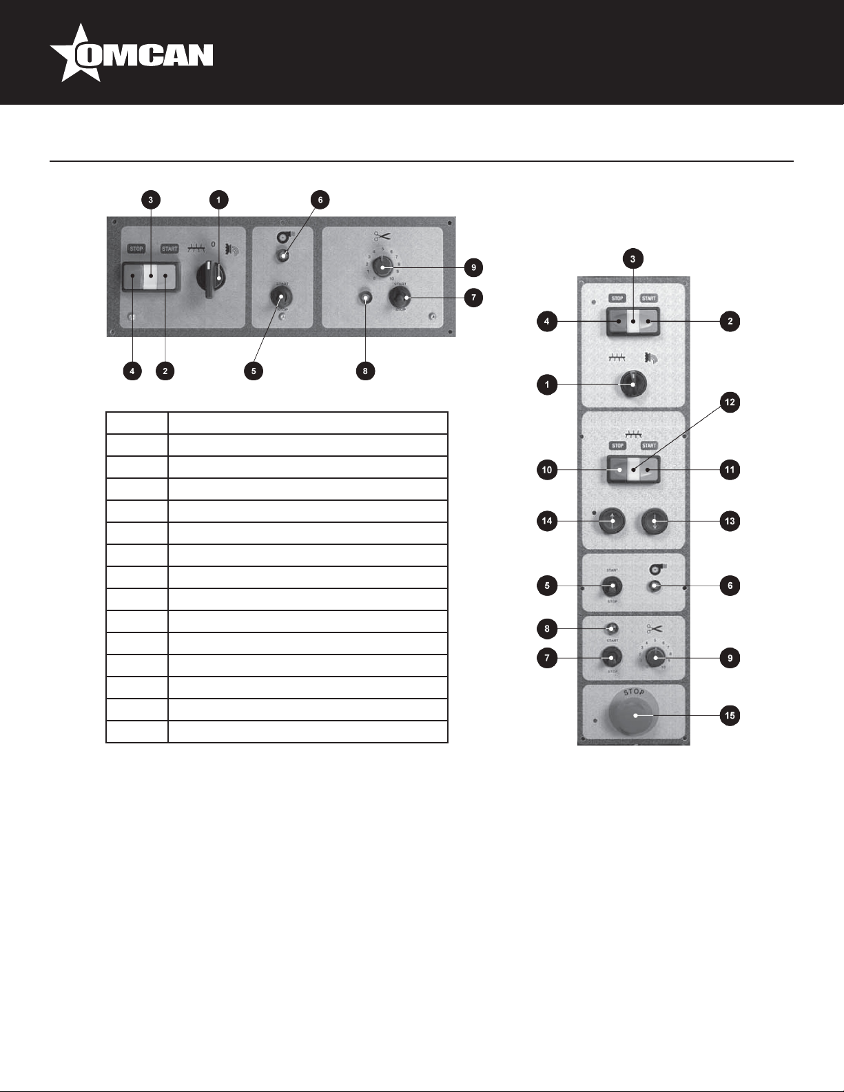
CONTROL PANEL KEY
1 KNEAD÷DRAW selector
2 Start button
3 Start pilot lamp
4 Stop push button
5 Fan switch
6 Fan pilot lamp
7 Cutter switch
8 Cutter operation pilot lamp
9 Cutter speed variation control
10 2nd tank mixer control stop button
11 2nd tank mixer control start button
12 2nd tank mixer operating pilot light
13 Tank lowering button only for TRD
14 Tank lifting button only for TRD
15 Emergency stop button only for TRD
Operation
1. After having turned the machine off:
• Switch the selector to the “0” position (Figure 20A) and check the correct set-up of the Worm screw,
making sure that the cylinder part is sustained by the dragging shaft.
• Then make sure that the plastic cap (Figure 21A) which replaces the drawplate is correctly positioned
and the ring nut (Figure 21B) is well-screwed on.
• Finally block the mixer in its place, thanks to the head-knob (Figure 21C).
2. Lift the tank lid by turning the coupling lever (Figure 22A) and always put in the pre-established ingredients
in the following sequence: our and then, after closing the cap, all the other liquid elements.
3. In order to obtain the right dough, you need to create the precise ratio between the weight of the our and
the weight of the liquid part; in order to obtain a very good product, the our has to contain a humidity
percentage of no more than 15%; this allows the addition of water equal to 33% or up to 35% of the our’s
weight. If you are using ours with different humidity contents, please change the quantity of the liquid
in the opposite ratio. Moreover, in order to better use the machine, the product inside the pool has to be
9
Page 10

Operation
higher than at a minimum level which coincides more or less with the position of the mixer axle.
USEFUL ADVICE IN ORDER TO OBTAIN A GOOD DOUGH
Any kind of our can be used (bran or branour). The dough can be kneaded only with eggs or with a mix of
water and eggs. Water can be partially replaced by spinach or well-cut vegetables in order to obtain green
noodles. Because the our’s humidity changes according to the kind used, the environment and the place
where it is stocked, the quantities indicated have to be adapted to the kind of our which is used, lowering or
increasing the quantity of water. The dough is the right one when, at the end of kneading process, it is as big
as coffee beans. If the lumps form in the our, you have poured in too much liquid.
In this case, before turning the switch (Figure 20A) from knead to drawplate, you will have to add some more
our and knead a little longer. If the our does not form a ball and is too oury, add some more water.
For the dough for the sheet of pasta which is to be re-kneaded, use “00” our and add two eggs per kilo of our
(maximum). With these quantities, you will obtain a very stretchy dough which is easy to knead.
QUANTITIES IN ORDER TO OBTAIN A GOOD DOUGH
• Supposed weight of an egg: 50 grams.
• If you take 1 egg away you need to add 50 grams of water.
• To obtain a good dough: 1 kg of our + 350 grams of humidity-liquid.
FLOUR-EGG MIXTURE FLOUR-EGG-WATER MIXTURE
Flour daN Egg No. Mixture daN Flour daN Egg No. Water l Mixture daN
1 7 1,35 1 4 0,15 1,35
2 14 2,70 2 8 0,30 2,70
3 21 4,05 3 12 0,45 4,05
4 28 5,40 4 16 0,60 5,40
5 35 6,75 5 20 0,75 6,75
6 42 8,10 6 24 0,90 8,10
7 49 9,45 7 28 1,05 9,45
8 56 10,80 8 32 1,20 10,80
9 63 12,15 9 36 1,35 12,15
10 70 13,50 10 40 1,50 13,50
• Close the lid and put the selector on position . Press the start button.
• Add the liquid part pouring it gradually but as quickly as possible through the small hole in the lid.
• At the end of the kneading operation, which should take around 10 minutes, make sure the product has the
right thickness and should look like coffee beans (check through the small holes of the lid).
• Turn the machine off by switching the selector to “0.”
10
Page 11

Operation
INSTALLATION OF THE DRAWPLATE AND START-UP OF PRODUCTION
WARNING: Make sure the machine is switched off.
• Withdraw the lter (Figure 8A) and the drawplate (Figure 8B) requested from the container lled with water
where it was put after its last use. Thoroughly rinse with plenty of running, warm water, in order to have the
piece at the right temperature (See Maintenance section).
• Dry it with a soft cloth.
• Unscrew the blocking ring nuts (Figure 8C) and carefully clean the internal part including the edging.
• Take the plastic cap off (Figure 8D).
• Set up the lter and the drawplate while taking good care of the Worm screw (Figure 8E) at the center of
the disk.
• Close the metal ring with the help of the wrench supplied (Figure 9A) and check that the various parts are
in place and are not shifted axially because dough has added thickness (Figure 8 - point 1).
• In order to start production, position the selector (Figure 10A) on the position and press the start button
(Figure 10C). The initial product coming out of the machine has an unacceptable appearance; this is the
reason why it has to be eliminated.
• After a short time (a couple of minutes), the product coming out is acceptable - the colour goes from whitish
to yellow and it has a greater consistency.
• In order to cut the pasta to the desired length, it is necessary to set up the cutting device (Figure 9B), made
up of motor and knife, chosen from those available.
• Set up the unit for this, by simply tting the cutter (Figure 11A) on the drive shaft in the standby position.
Placing the cutting unit opposite the drawplate, taking care that the cutter moves axially towards the motor
and is ts neatly with the drawplate.
• To complete this operation, facilitate the movement of the knife by helping yourself, with your hands,
closing the knife tang between two ngers (Figure 11).
• Regulate the knife speed according to the desired pasta length, by turning the speed control knob
(Figure 10B).
• If the product is quite wet and tends to be sticky, it is best to dry the surface in any case, by switching on
the fan (Figure 10D).
• The product may be collected on the frame supplied (Figure 12A), leaning on retractable rods (Figure 12B)
supplied with the machine.
For machines tted with an extrusion sleeve cooling unit:
• Switch on the system taking account of a few operating parameters of the dough and room temperature.
• At any rate, with average dough, after 3 - 5 minutes, check the external temperature of the ring nut and if it
seems too high, gradually open the regulating valve. Frequently check the temperature and regulate water
ow, tending to keep temperature constant.
NOTE: If the product is kneaded at an excessive temperature, it tends to change colour and/or blanch slightly.
VARIANT FOR MODEL PM-IT-0040
The model PM-IT-0040 uses the second tank (Figure 14B) to enable dough to be kneaded (press button
A - Figure 13) simultaneously with the worm screw extrusion stage. This allows output to be increased
considerably. Knead the dough as seen for the main tank and then pour it in by turning the tank by means of
the device provided (button B - Figure 13).
11
Page 12

Operation
• To do this, rst lift the lid of the bottom tank (Figure 14A) even if this causes the machine to stop. The
new product must have the same consistency as the previous contents of the tank so as to achieve a
homogeneous dough mixture.
DANGER: While the tank is lowered, make sure the area near the lift (Figure 15A) is vacated as the control
protection guard (Figure 15B) may be dangerous in the nal stage of the movement (squeezing or cutting
dangers).
After the operation:
• Stop the machine by switching the selector (Figure 16A) as well as the others to the “0” position.
• Rotate the cutting group to the stop position (Figure 17).
• Turn the selector (Figure 16B) to the knead position for 10-15 seconds in order to eliminate the
pressure on the die caused by the product.
• Return the switch to “0.”
• Disassemble and wash the movable parts (Figures 18 - 19) and clean the machine (see Maintenance
section).
• Close the water tap, for machines tted with a cooled extrusion sleeve.
MACHINE WHIRR
The whirring noise emitted by the machine has been measured on an identical sample machine in compliance
with standard DIN 45635. A constant value not exceeding 70 dB(A) was measured as stated in the
manufacturer’s test report.
STRIPPING-DOWN AND DEMOLISHING THE MACHINE
If the machine needs to be stripped-down and/or demolished, its components do not entail a degree of danger
that require any particular precaution. Remember, however, that to facilitate material recycling operations, it is
a good rule to remove electrical system components from the machine.
Maintenance
WARNING: For healthy and hygienic processing of food products, be sure to keep your machine and the
surrounding environment clean.
DANGER: Always cut off the power supply before cleaning.
You have to properly clean all the elements which are in contact with the product (Figures 18 and 23)
protection lid, pool, mixer, Worm screw, drawplate, lter, ring nut and knife, when the product is still soft. The
moving parts have to be disassembled as follows:
MIXER
• Make sure the external shovel (Figure 23A) is in the upper vertical position (only this position allows the
disassembling of the piece) (Figure 23).
12
Page 13

Maintenance
• Disassemble the mixer by unscrewing the external movable support (Figure 23B) until releasing the mixer;
unthread the shaft from its place and at the same time, rotate the external pin towards the top.
• If you want to assemble the piece follow these instructions vice versa. Line the central point of the shaft
with the peg of the moving support; thereafter, screw the support, but without blocking it.
METAL RING, DRAWPLATE AND FILTER
Unscrew the metal ring with the appropriate wrench (Figure 24A) while being careful not to let any pieces fall.
Since the metal ring is moved from its place, the product and parts still weigh a few kilos and can easily slip
from your hands, causing damage both to people or to the pieces themselves.
WORM SCREW
After disassembling the ring nut, the drawplate (Figure 24B) and the lter, the Worm screw can easily be taken
off the machine by pushing its spiral from the internal end.
LID AND POOL CLEANING
Eliminate the dough residue and be sure to thoroughly clean the most remote-access pieces: connections of
the Worm screw (Figure 25A) and mixer movements (Figure 25B), extrusion sleeve (Figure 25C), pool internal
parts and lid grille in the grille coupling points (Figure 25D).
Use some warm water in order to eliminate the residual product and then rinse; dry the surfaces with the help
of blotting paper and disinfectant, with a soft cloth dipped in odourless disinfectant
WARNING: Never use non-nutritional, abrasive or corrosive chemicals to clean. Also never use coarse or
abrasive objects such as steel wool, abrasive sponges and so on.
To clean the internal and external parts of the machine:
• Remove power supply plug from power mains socket.
• Clean coated surfaces with soft cloth and disinfect with alcohol.
• For the inside parts of the machine, take off the back panel (Figure 26) and carry out the cleaning of the
machine, bearing in mind the grease and dust, that are sometimes present.
• Lastly, t the panels again.
CLEANING OF MIXER, WORM SCREW, METAL RING, FILTER, DRAWPLATE AND KNIFE
• Eliminate the dough residue and wash the pieces with water; you may use a soft brush or a plastic pallet
knife.
• These elements can be thoroughly washed in a dishwasher.
• Rinse and dry the mixer, the Worm screw, the metal ring and the knife and reassemble them on the
machine. The drawplate and lter must be kept in a container placed in water for the entire period in which
they are not being used.
For reasons of hygiene, please change the water every day.
MAINTENANCE AND ADJUSTMENT
WARNING: Remember that all maintenance operations are dangerous if you do not rst disconnect the power
supply plug from the power mains.
13
Page 14

Maintenance
• The machine parts requiring maintenance are the following: the upright push-bearing support (Figure 29B),
the movable mixer support (Figure 27) and the sliding chain (Figure 29A).
• Carry out the rst maintenance job after the rst 100 hours of operation and subsequently every 500 hours.
• Remove the rear panel to gain access to the chain (Figure 26A) and the bearing support (Figure 29B).
• Use food-grade grease compliant with USDA-H1 regulations for the mixer support (Figure 27); (if
necessary, contact your local dealer). Use SAE MR3 type grease for the thrust bearing support (Figure
29B) and the chain (Figure 29A).
• When doing a yearly check-up, lubricate the chain (Figure 29A) using smaller amounts of grease.
BELT TIGHTENING
When performing the above mentioned maintenance or when the machine is not working properly, (loss of
rounds) check the correct stretching of the transmission belt. For this reason, disassemble the rear panel from
the machine and make sure that the belt (Figures 26, 28, 30C) is tight enough. If necessary, use the regulating
system (Figures 26B, 28A, 30A), by moving the motor and therefore, tightening the belt, without of course
exaggerating. When nished, t the panel back.
WARNING: Never use the machine with any missing, disassembled or open guards and shields.
WARNING: If servicing operations require repairs to the electrical system and/or replacement of bearings or
mechanical components, call an expert technician or your local dealer.
Troubleshooting
SYMPTOMS POSSIBLE CAUSE REMEDY
Machine operation failure. Disconnected plug. Connect plug.
Plug leads not correctly connected. Check lead connections.
The product gets stuck when
being poured out.
The product looks
unacceptable even after the
initial minutes: it breaks and
loses our.
Trip switch adjusted for insufcient
values.
Unsuitable trip switch. Replace trip switch.
Fuses burnt out. Replace fuse.
Safety lever on pool lid not properly
inserted.
Too humid dough is used. Reduce the quantity of water used
Too short kneading time. Increase the kneading time.
Not enough water percentage. Increase the quantity of water in
Adjust trip switch accordingly.
Position the lever at end of stroke.
for the dough respecting the above
mentioned percentage.
order to respect the aforementioned
percentage.
14
Page 15

Troubleshooting
The product does not come
out of the drawplate.
The product crushed at an
edge during cutting.
The blocking of the drawplate
because of dried dough.
Cutting speed not adequate (too low). Increase cutting speed: remember
Disassemble and clean the
drawplate.
that the length of the pasta cut,
depends on the pasta.
REFERENCE
Item Number Model Number Description Manufacturer Model Number
13364 PM-IT-0008
13397 PM-IT-0015
16643 PM-IT-0025
13236 PM-IT-0025-T
13440 PM-IT-0040
Pasta Machine 18 lb / 8 kg per Hour
0.75 HP / 559 W 110V/60/1
Pasta Machine 33 lb / 15 kg per Hour
1 HP / 746 W 220V/60/1
Pasta Machine 55 lb / 25 kg per Hour
1.5 HP / 1119 W 220V/60/1
Pasta Machine 55 lb / 25 kg per Hour
1.5 HP / 1119 W 208V/60/3
Pasta Machine 88 lb / 40 kg per Hour
1.5 HP / 1119 W 208V/60/3
TR75
TR95
TR110
TR1103PH
TRD110
Figure 1
Illustrated Drawings
Figure 3
Figure 2
15
Page 16

Illustrated Drawings
Figure 4
Figure 5 Figure 6
Figure 7
Figure 8
Figure 9
Figure 10
Figure 14
Figure 12
Figure 11
Figure 15
Figure 13
16
Page 17

Illustrated Drawings
Figure 17
Figure 16
Figure 19 Figure 20
Figure 23
Figure 22
Figure 18
Figure 21
Figure 24
17
Page 18

Illustrated Drawings
Figure 25
Figure 28
Figure 27
Figure 26
Figure 29
18
Figure 30
Page 19

Parts Breakdown
Model PM-IT-0008 13364
Item No. Description Position Item No. Description Position Item No. Description Position
44115 Worm for TR75 1 77693 Spacer for TR75 20 77712 Protection for TR75 39
77675 Sleeve for TR75 2 77694 Upper Sprocket Z=18 3/8 for TR75 21 77713 Knife Support for TR75 40
77676 Lock Ring for TR75 3 77695 Fattener for TR75 22 77714 Cap Sleeve for TR75 41
77677 Support Mobile Mixing for TR75 4 77696 Reducer Pulley for TR75 23 77715 Quick Connect Plug for TR75 42
77678 Bearing 62206 for TR75 5 77697 Gasket for TR75 24 77716 Knife Blade for TR75 43
77679 Pin for TR75 6 77698 Bearing 51206 for TR75 25 77717 Knife Blade for TR75 44
77680 Fixed Support for TR75 7 77699 Bearing 6006 for TR75 26 77718 3/8 Chain for TR75 45
77681 Bath for TR75 8 77700 Rings for TR75 27 77719 Motor for TR75 46
77682 Mixer for TR75 9 77701 Lower Shaft for TR75 28 77720 Micro Switch MS30 for TR75 47
77683 Cover for TR75 10 77702 Lower Sprocket Z=23 3/8 for TR75 29 77721 Micro Switch MS09 for TR75 48
77684 Cam for TR75 11 77703 Spacer for TR75 30 77722 Cater Back for TR75 49
77685 Handle for TR75 12 77704 Rod for Motor Base for TR75 31 77723 Lower Cater for TR75 50
77686 Fan for TR75 13 77705 Belt 670 50Hz 710 60Hz for TR75 32 77724 Back for TR75 51
77687 Rod for TR75 14 77706 Motor Base for TR75 33 77725 Bracket for Fan for TR75 52
77688 Plate for TR75 15 77707 Motor Pulley for TR75 34 77726 Nylon Bushing for TR75 53
77689 Wheel for TR75 16 77708 Tensioning Screw for TR75 35 77727 Round Door Knife Support for TR75 54
77690 Ring for TR75 17 77709 Washer for TR75 36 77728 Electrical Assembly for TR75 55
77691 Upper Shaft for TR75 18 77710 Motor Cover for TR75 37 77729 Micro Switch FR515 for TR75 56
77692 Adapter MVF49 for TR75 19 77711 Knife Motor for TR75 38
19
Page 20

Parts Breakdown
Model PM-IT-0015 13397
Item No. Description Position Item No. Description Position Item No. Description Position
77730 Screw for TR951PH 1 77747 Upper Shaft for TR951PH 22 77764 Fattener for TR951PH 40
77731 Sleeve for TR951PH 2 77748 Reducer Pulley for TR951PH 23 77765 Micro Switch MS30 for TR951PH 41
77732 Lock Ring for TR951PH 3 77749 Adapter TA30 for TR951PH 24 77766 Micro Switch FR515 for TR951PH 42
77733 Moving Knife Support for TR951PH 4 77750 Spacer for TR951PH 25 77767 Micro Switch MS09 for TR951PH 43
77734 Fixed Support for TR951PH 5 77751 Double Chain 3/8 for TR951PH 26 77768 Electrical Assembly for TR951PH 44
77735 Knife Motor for TR951PH 6 77752 Bearing 6008 for TR951PH 27 77769 Bushing for TR951PH 45
77736 Knife Blade for TR951PH 7 77753 Bearing 51308 for TR951PH 28 77770 Shaft Motor Base for TR951PH 46
77737 Knife Blade for TR951PH 8 77754 Lower Shaft for TR951PH 29 77771 Cap Sleeve for TR951PH 47
77738 Support for TR951PH 9 77755 Lower Sprocket Z=23 3/8 for TR951PH 30 77772 1/4 Tubes for TR951PH 48
77739 Bearing 62206 for TR951PH 10 77756 Back Movement Support for TR951PH 31 77773 Nipple Fittings for TR951PH 49
77740 Mobile Shaft for TR951PH 11 77757 Belt 1180 for TR951PH 32 77774 3/8 Flexible Tube for TR951PH 50
77741 Fixed Support for TR951PH 12 77758 Motor Pulley for TR951PH 33 77775 Fittings for TR951PH 51
77742 Cover for TR951PH 15 77759 Motor HF80 for TR951PH 34 77776 Reducer for TR951PH 52
77743 Cam for TR951PH 16 77760 Motor Base for TR951PH 35 77777 1/4 Elbows for TR951PH
77744 Wheel for TR951PH 18 77761 Sieve Support Rods for TR951PH 36 77778 Hose for TR951PH 54
77745 Bearing 6206 for TR951PH 19 77762 Fan for TR951PH 37 77779 1/4 Gasket for TR951PH 55
77746 Upper Sprocket Z=18 3/8 for TR951PH 20 77763 Fan Base for TR951PH 38
53
20
Page 21

Parts Breakdown
Model PM-IT-0025 16643
Model PM-IT-0025-T 13236
Item No. Description Position Item No. Description Position Item No. Description Position
37967 Worm for TR110 1 77791 Upper Sprocket Z=22 3/8 for TR110 20 77808 Knife Shelf Protection for TR110 39
77780 Sleeve for TR110 2 77792 Upper Shaft for TR110 22 77809 Fattener for TR110 40
31248 Die Retaining Ring for TR110 3 77793 Reducer Pulley for TR110 23 77810 Micro Switch MS30 for TR110 41
77781
77782 Fixed Support for TR110 5 77795 Spacer for TR110 25 77812 Micro Switch MS09 for TR110 43
14565 Motor with Plug for TR110 Cutter 6 77796 Double Chain 3/8 for TR110 26 77813 Electrical Assembly for TR110 44
16280 Single Blade TR110 7 77797 Bearing 6008 for TR110 27 77814 Bushing for TR110 45
77784 Knife Blade for TR110 8 77798 Bearing 51308 for TR110 28 77815 Shaft Motor Base for TR110 46
44867
77785 Bearing 62204 for TR110 10 77800 Lower Sprocket Z=23 3/8 for TR110 30 77817 1/4 Tubes for TR110 48
77786 Mobile Shaft for TR110 11 77801 Back Movement Support for TR110 31 77818 Nipple Fittings for TR110 49
77787 Fixed Support for TR110 12 77802 Belt 1180 for TR110 32 77819 3/8 Flexible Tube for TR110 50
39487 Mixer for TR110 13 77803 Motor Pulley for TR110 33 77820 Fittings for TR110 51
77788 Cover for TR110 15 39081 Motor Main 220/60/1 for TR110 34
39623 Cam for TR110 16 77804 Motor Base for TR110 35 77822 1/4 Elbows for TR110 53
39665 Cover with Handle for TR110 17 77805 Sieve Support Rods for TR110 36 77823 Hose for TR110 54
77789 Wheel for TR110 18 77806 Fan for TR110 37 77824 1/4 Gasket for TR110 55
77790 Bearing 6206 for TR110 19 77807 Fan Base for TR110 38
Use #14564 Moving Knife Support
for TR110
Rotating Mixer Support Complete of
Bearing and Shaft for TR110
4 77794 Adapter TA30 for TR110 24 77811 Micro Switch FR515 for TR110 42
9 77799 Lower Shaft for TR110 29 77816 Cap Sleeve for TR110 47
77821 Reducer for TR110 52
21
Page 22

Parts Breakdown
Model PM-IT-0040 13440
Item No. Description Position Item No. Description Position Item No. Description Position
37967 Worm for TRD110 1 77845 Bearing 4200 2RS for TRD110 21 77811 Micro Switch FR515 for TRD110 42
77780 Sleeve for TRD110 2 77792 Upper Shaft for TRD110 22 77812 Micro Switch MS09 for TRD110 43
31248 Die Retaining Ring for TRD110 3 77793 Reducer Pulley for TRD110 23 77814 Bushing for TRD110 45
77781
77782 Fixed Support for TR110/TRD110 5 77849 Tensioner Roller for TRD110 25 77816 Cap Sleeve for TRD110 48
14565 Motor with Plug for TRD110 Cutter 6 45190 Chain for TRD110 26 77871 Wheel 2 for TRD110 49
16280 Single Blade TRD110 7 77797 Bearing 6008 for TRD110 27 77872 Reducing Shaft 2 for TRD110 50
77784 Knife Blade for TR110 8 77798 Bearing 51308 for TR110/TRD110 28 77873 Pin for Roller Tensioner for TRD110 51
10901
77835 Fixed Support for TRD110 12 77800 Lower Sprocket Z=23 3/8 for TRD110 30 77875 Lubed Bushing for TRD110 53
39487 Mixer for TRD110 13 77801 Back Movement Support for TRD110 31 41192 Gas Spring for TRD110 54
77837 Mixer for Bath 2 for TRD110 13A 77855 Belt SPZ 1202 for TRD110 32 77876 Motor MVF 49 for TRD110 55
77838 Handle for TRD110 14 77803 Motor Pulley for TRD110 33 77877 Roller Bracket for TRD110 56
77839 Hopper Cover for TRD110 15 39081 Motor Main 208/60/3 for TRD110 34
39623 Cam for TR110/TRD110 16 77804 Motor Base for TRD110 35 77879 Cam for Cover for TRD110 58
40030 Tank Lid Cover for TRD110 17 77805 Sieve Support Rods for TRD110 36 77880 Knob for Release Tank for TRD110 59
77789 Wheel for TRD110 18 77806 Fan for TRD110 37 77881 Rear Wheels for TRD110 60
77842 Wheel 1 for TRD110 18A 77861 Plug-in Fittings for TRD110 38 77882 Pivoting Front Wheels for TRD110 61
77843 Bearing 6206 2RS for TRD110 19 15432 Cutter Protection for TRD110 39 77883 Fan Bracket for TRD110 62
77791 Upper Sprocket Z=22 3/8 for TRD110 20 77809 Fattener for TRD110 40 77884 Solenoid for TRD110 68
Use #14564 Moving Knife Support
for TRD110
Rotating Mixer Support with Bearing and
Shaft for TRD110
4 77794 Adapter TA30 for TRD110 24 77815 Shaft Motor Base for TR110/TRD110 46
9 77799 Lower Shaft for TRD110 29 77874 Locking Screw for TRD110 52
77878 Bath Lid 2 for TRD110 57
22
Page 23

Model PM-IT-0008 13364
Parts Breakdown
23
Page 24

Parts Breakdown
Model PM-IT-0015 13397
24
Page 25

Model PM-IT-0025 16643
Model PM-IT-0025-T 13236
Parts Breakdown
25
Page 26

Parts Breakdown
Model PM-IT-0040 13440
26
Page 27

Model PM-IT-0008 13364
Electrical Schematics
Description Position Description Position Description Position
Relay K2 Thermal Protection Phase Motor RT1 Start Button PM
Stop PE Transformer TR Microswitch General FC1
Reversal INV Fuse Protection Ventilation 2A F1 Signaling Ventilation Function LV
Enabling Ventilation SV Fuse Protection 2A F2 Start Reposting General LM
Enabling Engine Cut ST Transformer Protection 1A F3 Signaling Cutting Function LT
Single-Phase Motor Control K1 Transformer Protection 1A F4
27
Page 28

Electrical Schematics
Model PM-IT-0015 13397
L1 L2
M2M1
Power line
220 VAC - Single-phase
M3
Power motor
Single-phase
220 VAC
2 6
T S R
Reverse Gear
W V U
3 5 11
+
B C DA
12
Inv
++
K1
1-13
TR95=9.5
M3M3M3
F
0
230 400
TR 100 VA
0 230 01 24
k2
F1
220 220
M1M1
Power Ventilation
A1
F2
K2
PE
SV
LV
1-5
1-5
1-5
1-15
General Start
PM
MICRO M3
FC1
MICRO M3
RT1
1-5
A1
LM
24V 24V
K1 14/22
95 NC
ST
LT
SPEED ADJUSTMENT
POTENTIOMETER
P1
SCEDA MOTOR
BOARD CUTTING KNIFE
24V 24V
Engine Power
Cutting Supply 24vdc
M1M1
Description Position Description Position Description Position
Relay K2 Thermal Protection Phase Motor RT1 Start Button PM
Stop PE Transformer TR Microswitch General FC1
Reversal INV Fuse Protection Ventilation 2A F1 Signaling Ventilation Function LV
Enabling Ventilation SV Fuse Protection 2A F2 Start Reposting General LM
Enabling Engine Cut ST Transformer Protection 1A F3 Signaling Cutting Function LT
Single-Phase Motor Control K1 Transformer Protection 1A F4
28
Page 29

Model PM-IT-0025 16643
Electrical Schematics
L1 L2
M2M1
Power line
220 VAC - Single-phase
M3
Power motor
Single-phase
220 VAC
2 6
T S R
Reverse Gear
W V U
3 5 11
+
B C DA
12
Inv
F
++
K1
1-13
TR110=12.50
M3M3M3
0
230 400
TR 100 VA
0 230 01 24
k2
F1
220 220
M1M1
Power Ventilation
A1
F2
K2
PE
SV
LV
1-5
1-5
1-5
1-15
General Start
PM
MICRO M3
FC1
MICRO M3
RT1
1-5
A1
LM
24V 24V
K1 14/22
95 NC
ST
LT
SPEED ADJUSTMENT
POTENTIOMETER
P1
SCEDA MOTOR
BOARD CUTTING KNIFE
24V 24V
Engine Power
Cutting Supply 24vdc
M1M1
Description Position Description Position Description Position
Relay K2 Thermal Protection Phase Motor RT1 Start Button PM
Stop PE Transformer TR Microswitch General FC1
Reversal INV Fuse Protection Ventilation 2A F1 Signaling Ventilation Function LV
Enabling Ventilation SV Fuse Protection 2A F2 Start Reposting General LM
Enabling Engine Cut ST Transformer Protection 1A F3 Signaling Cutting Function LT
Single-Phase Motor Control K1 Transformer Protection 1A F4
29
Page 30

Model PM-IT-0025-T 13236
Electrical Schematics
Electrical Schematics
Model PM-IT-0025-T 13236
Description Position Description Position Description Position
Relay K2 Thermal Protection Phase Motor RT1 Start Button PM
Stop PE Transformer TR Microswitch General FC1
Reversal INV Fuse Protection Ventilation 2A F1 Signaling Ventilation Function LV
Enabling Ventilation SV Fuse Protection 2A F2 Start Reposting General LM
Enabling Engine Cut ST Transformer Protection 1A F3 Signaling Cutting Function LT
Single-Phase Motor Control K1 Transformer Protection 1A F4
30
Page 31

Model PM-IT-0040 13440
Electrical Schematics
31
Page 32

Electrical Schematics
Model PM-IT-0040 13440
24
2
FC1
3
RT1
4
PS1
5
FC2
12
RT2
13
PS2
14
IV
PM1
K1 K2
S1
6
PM2
15
S2
K3
IS
100K
17
18
3
K2
SEL1
7
10
(1° tank)
Procedure
K1
Light Extruder
Scheda
Light Knives
Crouzet
KA1 S4
S3
Fan Relay
Fan Indicator
S2
K3S1K2
2° Light Mixes
Knead Dough Tank
Pos
8
9
K1
0
Knead
32
Page 33

Model PM-IT-0040 13440
Electrical Schematics
Description Position Description Position Description Position
Knead Extruder Contactor K1 Shelter tank, 1° FC1 Gear Tub, 2° PM2
Knead Extruder Contactor K2 Shelter tank, 2° FC2 Imp-traf selector SEL1
Thermal Knead Extruder RT1 Knife Guard FC3 Switch Knife Board IS
Impasta Bath Contactor, 2° K3 Stop Bath, 1° PS1 Fan Indicator IV
Impasta Bath Contactor, 2° RT2 Stop Bath, 2° PS2
Fan Relay KA1 Gear Tub, 1° PM1
33
Page 34

Notes
________________________________________________________________________________________
________________________________________________________________________________________
________________________________________________________________________________________
________________________________________________________________________________________
________________________________________________________________________________________
________________________________________________________________________________________
________________________________________________________________________________________
________________________________________________________________________________________
________________________________________________________________________________________
________________________________________________________________________________________
________________________________________________________________________________________
________________________________________________________________________________________
________________________________________________________________________________________
________________________________________________________________________________________
________________________________________________________________________________________
________________________________________________________________________________________
________________________________________________________________________________________
________________________________________________________________________________________
________________________________________________________________________________________
________________________________________________________________________________________
________________________________________________________________________________________
________________________________________________________________________________________
________________________________________________________________________________________
________________________________________________________________________________________
34
Page 35

Warranty Registration
Thank you for purchasing an Omcan product. To register your warranty for this product, complete the information below, tear off the card at
the perforation and then send to the address specied below. You can also register online by visiting:
Merci d’avoir acheté un produit Omcan. Pour enregistrer votre garantie pour ce produit, complétez les informations ci-dessous, détachez la
carte au niveau de la perforation, puis l’envoyer à l’adresse spécié ci-dessous. Vous pouvez également vous inscrire en ligne en visitant:
Gracias por comprar un producto Omcan usted. Para registrar su garantía para este producto, complete la información a continuación,
cortar la tarjeta en la perforación y luego enviarlo a la dirección indicada a continuación. También puede registrarse en línea en:
www.omcan.com/warrantyregistration.html
For mailing in Canada
Pour postale au Canada
Por correo en Canadá
OMCAN
PRODUCT WARRANTY REGISTRATION
3115 Pepper Mill Court,
Mississauga, Ontario
Canada, L5L 4X5
PRODUCT WARRANTY REGISTRATION
4450 Witmer Industrial Estates, Unit 4,
For mailing in the US
Pour diffusion aux États-Unis
Por correo en los EE.UU.
OMCAN
Niagara Falls, New York
USA, 14305
or Email to: service@omcan.com
Purchaser’s Information
Name: Company Name:
Address:
Telephone:
City: Province or State: Postal or Zip: Email Address:
Country: Type of Company:
Restaurant Bakery Deli
Dealer from which Purchased: Butcher Supermarket Caterer
Dealer City: Dealer Province or State: Institution (specify):
Invoice: Other (specify):
Model Name: Model Number: Serial Number:
Machine Description:
Date of Purchase (MM/DD/YYYY): Date of Installation (MM/DD/YYYY):
Would you like to extend the warranty? Yes No
Thank you for choosing Omcan | Merci d’avoir choisi Omcan | Gracias por elegir Omcan
35
Page 36

Since 1951 Omcan has grown to become a leading distributor of equipment and supplies to the North
American food service industry. Our success over these many years can be attributed to our commitment
to strengthen and develop new and existing relationships with our valued customers and manufacturers.
Today with partners in North America, Europe, Asia and South America, we continually work to improve
and grow the company. We strive to offer customers exceptional value through our qualied local sales
and service representatives who provide convenient access to over 3,500 globally sourced products.
Depuis 1951 Omcan a grandi pour devenir un des “leaders” de la distribution des équipements et
matériel pour l’industrie des services alimentaires en Amérique du Nord. Notre succès au cours de ces
nombreuses années peut être attribué à notre engagement à renforcer et à développer de nouvelles
et existantes relations avec nos clients et les fabricants de valeur. Aujourd’hui avec des partenaires en
Amérique du Nord, Europe, Asie et Amérique du Sud, nous travaillons continuellement à améliorer et
développer l’entreprise. Nous nous efforçons d’offrir à nos clients une valeur exceptionnelle grâce à
nos ventes locales qualiées et des représentants de service qui offrent un accès facile à plus de 3500
produits provenant du monde entier.
Desde 1951 Omcan ha crecido hasta convertirse en un líder en la distribución de equipos y suministros
de alimentos en América del Norte industria de servicios. Nuestro éxito en estos años se puede atribuir
a nuestro compromiso de fortalecer y desarrollar nuevas relaciones existentes con nuestros valiosos
clientes y fabricantes. Hoy con socios de América del Norte, Europa, Asia y América del Sur, que trabajan
continuamente para mejorar y crecer la empresa. Nos esforzamos por ofrecer a nuestros clientes valor
excepcional a través de nuestro local de ventas y representantes de los servicios que proporcionan un
fácil acceso a más de 3,500 productos con origen a nivel mundial.
 Loading...