

Page 1
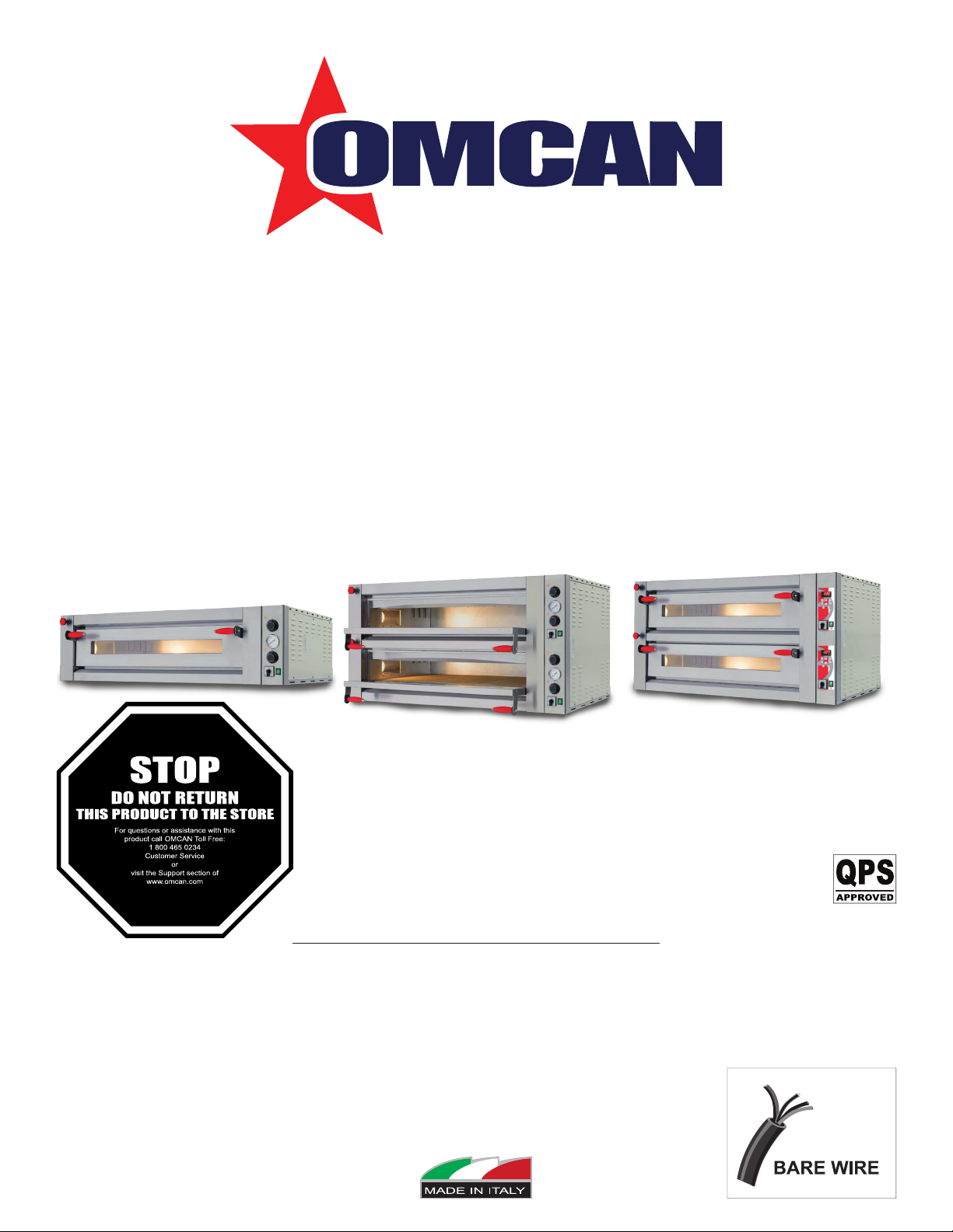
Pizza Ovens
Models PE-IT-0024-S, 0048-D, 0049-D, 0049-DD
Items 40637, 40638, 40641, 40643
Instruction Manual
Revised - 12/11/2019
Toll Free: 1-800-465-0234
Fax: 905-607-0234
Email: service@omcan.com
www.omcan.com
Page 2

Table of Contents
Model PE-IT-0024-S / Model PE-IT-0048-D
Model PE-IT-0049-D / Model PE-IT-0049-DD
Section
General Information
Safety and Warranty
Technical Specications
Installation
Operation
Maintenance
Troubleshooting
Parts Breakdown
------------------------------------------------------------------------------------------------------------- 6 - 7
------------------------------------------------------------------------------------------------------------- 8 - 14
------------------------------------------------------------------------------------------------------------- 15
------------------------------------------------------------------------------------------------- 3 - 4
------------------------------------------------------------------------------------------------- 4 - 6
--------------------------------------------------------------------------------------------------- 16 - 17
-------------------------------------------------------------------------------------------------- 18 - 27
Page
------------------------------------------------------------------------------------------------ 6
Electrical Schematics
Notes
Warranty Registration
----------------------------------------------------------------------------------------------------------------- 32 - 34
-------------------------------------------------------------------------------------------- 28 - 31
-------------------------------------------------------------------------------------------------- 35
2
Page 3

General Information
Omcan Manufacturing and Distributing Company Inc., Food Machinery of America, Inc. dba Omcan
and Omcan Inc. are not responsible for any harm or injury caused due to any person’s improper or
negligent use of this equipment. The product shall only be operated by someone over the age of 18, of
sound mind, and not under the inuence of any drugs or alcohol, who has been trained in the correct
operation of this machine, and is wearing authorized, proper safety clothing. Any modication to the
machine voids any warranty, and may cause harm to individuals using the machine or in the vicinity of
the machine while in operation.
CHECK PACKAGE UPON ARRIVAL
Upon receipt of an Omcan shipment please inspect for external damage. If no damage is evident on the
external packaging, open carton to ensure all ordered items are within the box, and there is no concealed
damage to the machine. If the package has suffered rough handling, bumps or damage (visible or concealed),
please note it on the bill of lading before accepting the delivery and contact Omcan within 24 hours, so we may
initiate a claim with the carrier. A detailed report on the extent of the damage caused to the machine must be
lled out within three days, from the delivery date shown in the shipping documents. Omcan has no recourse
for damaged products that were shipped collect or third party.
Before operating any equipment, always read and familiarize yourself with all operation and safety
instructions.
Omcan would like to thank you for purchasing this machine. It’s of the utmost importance to save
these instructions for future reference. Also save the original box and packaging for shipping the
equipment if servicing or returning of the machine is required.
---------------------------------------------------------------------------------------------------------------------------------------------------
Omcan Fabrication et distribution Companie Limité et Food Machinery d’Amerique, dba Omcan et
Omcan Inc. ne sont pas responsables de tout dommage ou blessure causé du fait que toute personne
ait utilisé cet équipement de façon irrégulière. Le produit ne doit être exploité que par quelqu’un de
plus de 18 ans, saine d’esprit, et pas sous l’inuence d’une drogue ou d’acohol, qui a été formé pour
utiliser cette machine correctement, et est vêtu de vêtements de sécurité approprié. Toute modication
de la machine annule toute garantie, et peut causer un préjudice à des personnes utilisant la machine
ou des personnes à proximité de la machine pendant son fonctionnement.
VÉRIFIEZ LE COLIS DÈS RÉCEPTION
Dès réception d’une expédition d’Omcan veuillez inspecter pour dommages externes. Si aucun dommage
n’est visible sur l’emballage externe, ouvrez le carton an de s’assurer que tous les éléments commandés
sont dans la boîte, et il n’y a aucun dommage dissimulé à la machine. Si le colis n’a subi aucune mauvaises
manipulations, de bosses ou de dommages (visible ou cachée), notez-le sur le bond de livraison avant
d’accepter la livraison et contactez Omcan dans les 24 heures qui suivent, pour que nous puissions engager
une réclamation auprès du transporteur. Un rapport détaillé sur l’étendue des dommages causés à la machine
doit être rempli dans un délai de trois jours, à compter de la date de livraison indiquée dans les documents
d’expédition. Omcan n’a aucun droit de recours pour les produits endommagés qui ont été expédiées ou cueilli
par un tiers transporteur.
3
Page 4

General Information
Avant d’utiliser n’importe quel équipement, toujours lire et vous familiariser avec toutes les opérations
et les consignes de sécurité.
Omcan voudrais vous remercier d’avoir choisi cette machine. Il est primordial de conserver ces
instructions pour une référence ultérieure. Également conservez la boîte originale et l’emballage pour
l’expédition de l’équipement si l’entretien ou le retour de la machine est nécessaire.
---------------------------------------------------------------------------------------------------------------------------------------------------
Omcan Empresa De Fabricacion Y Distribucion Inc. Y Maquinaria De Alimentos De America, Inc. dba
Omcan y Omcan Inc. no son responsables de ningun daño o perjuicío causado por cualquier persona
inadecuada o el uso descuidado de este equipo. El producto solo podra ser operado por una persona
mayor de 18 años, en su sano juicio y no bajo alguna inuencia de droga o alcohol, y que este ha sido
entrenado en el correcto funcionamiento de esta máquina, y ésta usando ropa apropiada y autorizada.
Cualquier modicación a la máquina anúla la garantía y puede causar daños a las personas usando la
máquina mientras esta en el funcionamiento.
REVISE EL PAQUETE A SU LLEGADA
Tras la recepcion de un envio Omcan favor inspeccionar daños externos. Si no hay daños evidentes en el
empaque exterior, Habra el carton para asegurararse que todos los articulos solicitados ésten dentro de la
caja y no encuentre daños ocultos en la máquina. Si el paquete ha sufrido un manejo de poco cuidado, golpes
o daños (visible o oculto) por favor anote en la factura antes de aceptar la entrega y contacte Omcan dentro
de las 24 horas, de modo que podamos iniciar una reclamación con la compañia. Un informe detallado sobre
los daños causados a la máquina debe ser llenado en el plazo de tres días, desde la fecha de entrega que se
muestra en los documentos de envío. Omcan no tiene ningun recurso por productos dañados que se enviaron
a recoger por terceros.
Antes de utilizar cualquier equipo, siempre lea y familiarizarse con todas las instrucciones de
funcionamiento y seguridad.
Omcan le gustaría darle las gracias por la compra de esta máquina. Es de la mayor importancia para
salvar estas instrucciones para futuras consultas. Además, guarda la caja original y el embalaje para el
envío del equipo si servicio técnico o devolución de la máquina que se requiere.
Safety and Warranty
WARNINGS FOR THE INSTALLER
Check that the location of the oven is in compliance with local and national regulations.
• Adhere to the instructions in this manual.
• Do not execute electrical connections using temporary or uninsulated cables.
• Check that the ground connection of the electrical system is functioning properly.
• Always use individual safety devices and other means of protection in compliance with the law.
4
Page 5

Safety and Warranty
WARNING FOR THE USER
The conditions in the surrounding area where the machine will be installed must have the following
characteristics:
• The area must be dry.
• The area must have water and heat sources at an adequate distance.
• Ventilation and lighting must be suitable and comply with the hygiene and safety standards foreseen by
current laws.
• The oor must be at and compact to facilitate thorough cleaning.
• There must be no obstacles of any kind in the immediate vicinity of the machine that could effect the
machine’s normal ventilation.
In addition, the user must:
• Make certain to keep children away from the machine when it is operating.
• Adhere to the instructions in this manual.
• Not remove or tamper with the safety devices on the machine.
• Always pay careful attention to the work at hand and not use the machine when in a distracted state.
• Perform all operations with maximum safety and calm.
• Respect the instructions and warnings displayed on the machine labels.
The labels are accident prevention devices, and therefore must always be perfectly legible. If these should be
damaged and illegible, it is mandatory to replace them by requesting replacements from the Manufacturer.
• At the end of each working shift, before cleaning, maintenance or transfer operations, disconnect electrical
power.
WARNINGS FOR THE MAINTENANCE OPERATOR
Observe the instructions indicated in this manual.
• Always use individual safety devices and other protection means.
• Before starting any maintenance operations, make sure that the oven, it was used, is cooled down.
• If any of the safety devices is worn or faulty, the oven is also considered faulty and not to be used.
• Disconnect electrical power before intervening on electrical or electronic parts and connectors.
1 YEAR PARTS AND LABOUR WARRANTY
Within the warranty period, contact Omcan Inc. at 1-800-465-0234 to schedule an Omcan authorized
service technician to repair the equipment locally.
Unauthorized maintenance will void the warranty. Warranty covers electrical and part failures, not
improper use.
Please see https://omcan.com/disclaimer for complete info.
5
Page 6
Safety and Warranty
WARNING:
The packaging components are classied as normal solid urban waste and can therefore be disposed of
without difculty.
In any case, for suitable recycling, we suggest disposing of the products separately (differentiated
waste) according to the current norms.
DO NOT DISCARD ANY PACKAGING MATERIALS IN THE ENVIRONMENT!
Technical Specications
Model
Maximum
Temperature
Electrical
Power
Pizza per
Hour
Chamber
Dimensions
External
Dimensions
Weight
Item Number
PE-IT-0024-S PE-IT-0048-D PE-IT-0049-D PE-IT-0049-DD
450° C / 842° F
220V / 60Hz / 3Ph
6600 W 13200 W 18000 W
80 - 14” pizzas 120 - 14” pizzas 200 - 14” pizzas
27.6” x 27.6” x 5.9”
701 x 701 x 150mm
43” x 39.8” x 16.9”
1092 x 1011 x 429mm
253 lbs. / 114.8 kgs. 403.4 lbs. / 183 kgs. 509 lbs. / 230.9 kgs. 508.2 lbs. / 230.5 kgs.
40637 40638 40641 40643
(27.6” x 27.6” x 5.9”) x 2
(701 x 701 x 150mm) x 2
43” x 39.8” x 29.5”
1092 x 1011 x 749mm
(41.3” x 27.6 x 5.9”) x 2
(1049 x 701 x 150mm) x 2
56.9” x 39.8” x 29.5”
1445 x 1011 x 749mm
Installation
Installation must be executed by qualied personnel in compliance with local and national regulations.
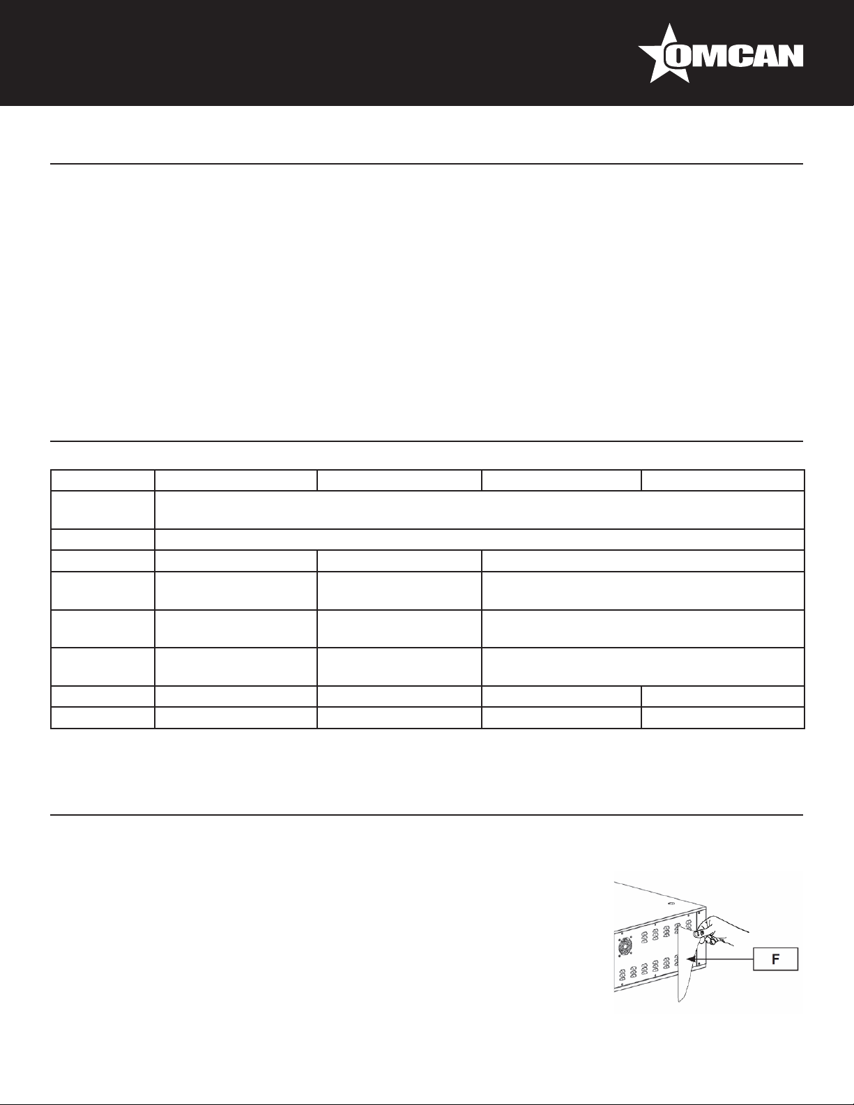
OVEN POSITIONING
Ensure that the oven is put on a stand with the suitable carrying capacity and
that is at.
After unpacking the oven from its packing, position it in prepared location, taking
into account the minimum distances.
Remove possible protections in polystyrene and take off the protecting lm (F)
6
Page 7

Installation
avoiding to use tools which can damage the surfaces.
EQUIPMENT HOOK-UP
Electrical connection
The oven is not provided with power supply cable. When connecting the appliance electrically, an automatic
RCD must be interposed with an opening distance between contacts of at least 3 mm. To connect the
appliance electrically it is essential to proceed in the following way:
• Remove the right side panel.
• Connect to the terminal block the power cable.
The power supply cable must be of H07-RNF type, with approved minimum cross section as prescribed by the
specic directive.
The electrical outlet must be easy to access, no moving should be necessary.
The electrical connection (plug) must be easily accessible, also following oven installation.
The distance between the machine and the socket must be adequate to not cause tension in the power supply
cable. In addition, the cable must not be located beneath the machine support base.
If the electrical power supply cable is damaged, it must be replaced by the technical assistance service
or by a qualied technician to prevent any risks.
GROUND CONNECTION
It is mandatory that the electrical system is equipped with a ground connection.
The appliance must be part of an equipotential system. The connection is done on terminal
marked with symbol which you will nd near the cable clamp. The section of the equipotential
wire must be at least 10mm2. The equipotential symbol is showed in the following gure.
7
Page 8
Operation
DIGITAL OVEN START UP AND USE
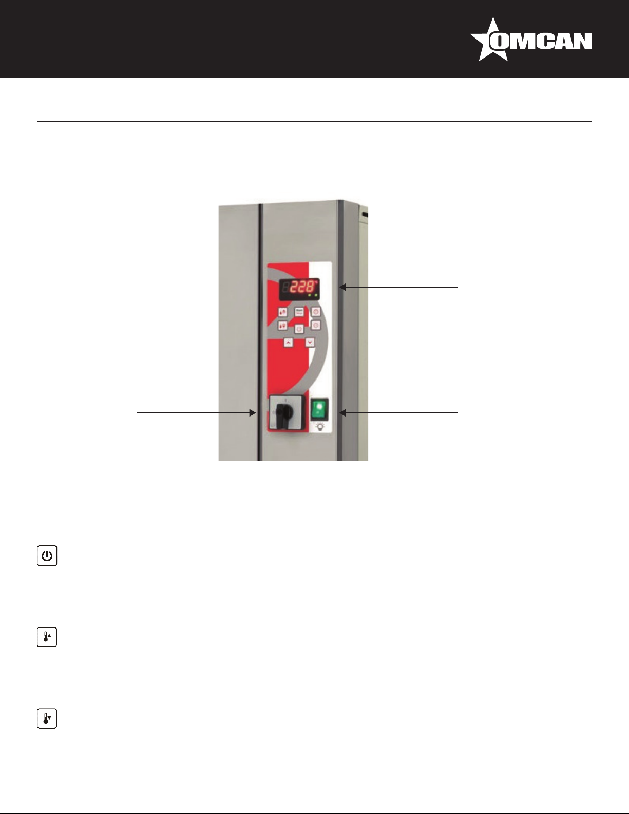
COMMAND PANEL DESCRIPTION
Digital control panel
Main switch
The digital control panel allows the separate setting of top heating’s elements and bottom heating’s elements,
furnishing in real time the information on the temperatures. It also allows the activation and set point of the
timer, and the delay of lighting.
Cooking chamber light switch
FUNCTION OF THE KEYS
ON/OFF KEY
When the digital control panel is in position Off (switched off) one push enables the switch on of the same.
When the digital control panel is “on”, the continuous push for three seconds enables shifting into “Off”
(switched off).
TOP KEY / P1 PROGRAM
When the digital control panel is active (and the display shows the average baking chamber temperature),
pushing once the touch programme 1 is taken back and signal “P1” is shown. A minimum three seconds lasting
push enables the modication of top temperature set (of the selected programme).
BOTTOM KEY / P2 PROGRAM
When the digital control panel is active (and the display shows the average baking chamber temperature), by
8
Page 9

Operation
pushing once the touch Programme 2 is taken back and “P2” is shown. A minimum three seconds lasting push
enables the modication of the bottom temperature (of the selected programme).
INCREMENT VALUE KEY / VISUALIZATION TOP TEMPERATURE
When the display shows the average baking chamber temperature, pushing once the touch top temperature is
shown. When programme modalities (p1 or p2) or other modalities active, same touch enables the increase of
the selected value.
DECREMENT VALUE KEY / VISUALIZATION BOTTOM TEMPERATURE
When the display shows the average baking chamber temperature, pushing once the touch bottom
temperature is shown. When programme modalities (p1 or p2) or other modalities, same touch enables
decrease of the selected value.
CLOCK KEY / DELAY TIME
When the digital control panel is active, three seconds continuous push enables to modify the switch on delay
(clock signal blinks)
COOKING TIMER KEY
When the digital control panel is active, a three seconds continuous push enables to modify the baking time
(timer signal blinks).
START/STOP KEY
When the digital control panel is active:
• After setting the delayed switch-on, the single push of start/stop touch enables the countdown of the
delayed switch on.
• When the delayed switch on countdown is under process, a three seconds lasting push of the start/stop
touch enables to disconnect the same.
• After setting the baking timer the single push of start/stop touch enables the baking timer countdown.
• When the baking timer countdown is under process a single push of start/stop enables to stop counting. A
further single push enables to activate again the counting.
• When the baking timer countdown is working, the three seconds lasting start/stop push enables to
deactivate the timer.
MEANING OF DISPLAY ICONS
°C
CELSIUS ICON: It is active when the temperature is set in Celsius.
FAHRENHEIT ICON: It is active when the temperature is set in Fahrenheit.
°F
9
Page 10

Operation
TOP TEMPERATURE ICON: It is active when the top probe temperature is showed on the display. This
icon ashes during the variation of the top temperature set point.
BOTTOM TEMPERATURE ICON: It is active when the bottom probe temperature is showed on the
display. This icon ashes during the variation of the bottom temperature set-point.
TIMER ICON: It is active during the timer countdown. This icon ashes during the timer set-point.
CLOCK ICON: It is active during the delay time countdown. This icon ashes during the delay time set-
point.
TOP HEATING ELEMENTS ICON: It is active when the top heating elements are turned on.
BOTTOM HEATING ELEMENTS ICON: It is active when the bottom heating elements are turned on.
FIRST LIGHTING OF THE OVEN
At the rst use of the appliance it is advisable to heat the empty oven to eliminate bad smells caused by the
refractory stones evaporation and the inner metallic parts.
Procedure:
• Fully open the exhauster valve.
• Set the main switch in the position “1” after checking that the oven is connected with the power supply.
• Heat up the heating elements by pushing the on/off switch on the digital control panel.
• Leave the oven working (empty) for at least 8 hours at the temperature of 300° C before proceeding to the
rst baking.
START UP PHASE
After connecting the oven to the electric net rotate the main switch in position “1”. The digital control panel light
on and the word off is shown on the display. At this stage it is possible to start heating the oven by pushing the
on/off touch, with the consequent the heating elements start-up (top and bottom) of the baking chamber. By
pushing the on/off touch a short lamp-test takes place, after that for roughly 5 seconds the programme under
process is shown (p1 or p2). At this stage the display shows the average baking chamber temperature and
the thermostat setting takes place. This operation consists of the electronic and automatic use of the heating
elements to reach and maintain the temperatures set in the used programme (p1 or p2).
FUNCTION OF DIGITAL CONTROL PANEL
The main functions of the digital control panel are:
• Visualization of the baking chamber temperatures (average top and bottom).
• Top and bottom temperatures setting of baking programmes p1 or p2 (see ex. nr.1).
• Baking timer setting and activation (see ex. nr 2).
• Delayed switch-on setting and activation (see ex. nr 3).
10
Page 11

Operation
GENERAL INDICATIONS FOR A GOOD COOKING
Generally for the food products it is not advisable to give precise temperature and baking time, because of their
different characteristics. Particularly, regarding pizza and similar products, time and temperatures depend on
the shape and thickness of the dough, as well as on the quantity and typology of the additional ingredients.
For those reasons it is always advisable to carry out previously some baking tests, (particularly when it is an
absolute new oven), with the aim of understanding as much as possible the characteristics and the functioning
of the oven.
Ideal time and temperature choice is determinant for a right pizza baking; mostly they depend on the
operator’s experience.
WORKING PHASE
While working, at any time the oven can be modied in its temperature parameters and programs; in addition,
pizza baking operation can be veried by inner chamber light. Once the oven has reached the set temperature
(visible on the display), it is possible to put in the pizza/s for baking, proceeding as follows:
• Open the door of the oven by the suitable handles.
• To light the inner chamber, set the lighting button (B) in the position “1”.
• Put in the oven the pizza/s to bake with suitable instruments for said use.
• Close the door again by the suitable handles and check the baking through the door glass. If wished, it is
possible to set the baking timer, which will warn with an acoustic signal the set baking time expiry.
• At baking over, open the door by the suitable handles and take out the pizza/s by suitable instruments for
said use.
When opening the door while the oven is on, it is important to stay at the right distance, to avoid being
invested by the heat coming out from the chamber.
Use suitable instruments to bake in and displace the pizzas in the baking chamber, to avoid burns.
When opening the door to bake the pizza/s, do not leave it opened for long time, to avoid heat
dispersion and consequently chamber temperature drop.
Avoid oil and fats to drop on bottom; if brought at high temperature can burn.
QUICK PROGRAM ACCESS
Press the TOP key to access the temperature setpoints related to program 1 (parameters P3 and P4), press
instead the BOTTOM key to access the temperature setpoints related to program 2 (parameters P5 and P6).
When pressing the TOP or BOTTOM key, the display shows the selected program for 5 seconds (Pr 1 in green
or Pr 2 in red). The setpoints are updated when the label disappears. If while Pr 1 or Pr 2 is displayed the TOP
or BOTTOM key is pressed, this display will disappear and the setpoints are updated. With the card ON, press
the TOP and BOTTOM keys for 3 seconds to display the program in use for 5 seconds. The selected program
is maintained also if the card is set to OFF or if the power is interrupted.
11
Page 12

Operation
SETTING THE DATE AND TIME
The date and time must be set when the expansion with RTC is used for delayed start (parameter P20 = 2).
With the card OFF, press the CLOCK key for 3 seconds, and the display will show the label dd followed by the
day of the week from 1 to 7 (1= Monday, 7 = Sunday). Use the UP and DOWN keys to set the day of the week
and conrm by pressing the CLOCK key. Set the hours (label hh) and minutes (label mm) in the same way.
After conrming the minutes with the CLOCK key, the card will return to OFF.
NOTE: if P20=2, but the correct expansion is not installed (with RTC) an error is displayed (RTC label
ashing) at the end of the date and time setting procedure.
SETTING DELAYED START
The delayed start can be set only when the card is on and the timer is not being used for counting. Delayed
start can be set for the same day and for the following 6 days (for example, on Wednesday it is possible to
set the programmed start until maximum next Tuesday). From the day on which the rst delayed start is set,
the card will turn on EVERY DAY at the set time until the delayed start is turned off. Press the CLOCK key for
3 seconds, the display will show the ashing dd label followed by the day of the week from 0 to 7 (0=delayed
start off, 1=Monday, 7=Sunday). Use the UP and DOWN keys to set the day of the week and conrm by
pressing the CLOCK key. Set the hours (ashing hh label) and minutes (ashing mm label) in the same way.
After conrming the minutes with the CLOCK key, the card will turn OFF and with the clock icon on and the
central dotpoints ashing. To display the programmed start date, press the CLOCK key and the day of the
week, time and minutes of the programmed start time will be displayed. The card can be used by pressing the
ON/OFF key and setting it to the on status. If the card is turned off, the indication of the delayed start will be
redisplayed (ashing dotpoints and clock icon on). To disable the programmed start, turn on the card, access
the delayed start setting and disable it by setting dd to zero.
NOTE: If the card turns on in error because the user forgot to turn off the daily delayed start, the oven
will turn off automatically after P23 hours after starting if no key is pressed. Set P23=0 to disable this
function.
USE OF EXAUSTER VALVE
By the exhauster valve the operator can regulate the baking steams and fumes ow out from the baking
chamber, while in the same the heat is kept. It is advisable to keep the valve fully closed when the oven is
under heating; so, the set temperature is reached in shortest possible time. While baking regulate the valve
according to the exigencies.
SHUT DOWN PHASE
To shut down the oven, press the power button on the digital control panel and then turn the main switch to the
position “0”.
12
Page 13

MECHANICAL OVEN START UP AND USE
COMMAND PANEL DESCRIPTION
Operation
Top heating elements
function pilot light
Bottom heating elements
function pilot light
Main switch
Thermostat for the regulation
of top temperatures
Digital control thermometer
Thermostat for the regulation
of bottom temperatures
Cooking chamber light switch
FIRST LIGHTING OF THE OVEN
At the rst use of the appliance it is advisable to heat the empty oven to eliminate bad smells caused by the
refractory stones evaporation and the inner metallic parts.
Procedure:
• Fully open the exhauster valve.
• Set the main switch in the position “1” after checking that the oven is connected with the power supply.
• Leave the oven working (empty) for at least 8 hours at the temperature of 300° before proceeding to the
rst baking.
START UP PHASE
After connecting the oven to the electric net rotate the main switch in position “1”. The digital thermometer
display shows the actual average temperature of the baking chamber. Rotate the thermostat knobs and until
the expected temperature. In this way top and bottom heating elements are under working and the relevant
light signals switch on.
GENERAL INDICATIONS FOR A GOOD COOKING
Generally for the food products it is not advisable to give precise temperature and baking time, because of their
different characteristics. Particularly, regarding pizza and similar products, time and temperatures depend on
13
Page 14

Operation
the shape and thickness of the dough, as well as on the quantity and typology of the additional ingredients.
For those reasons it is always advisable to carry out previously some baking tests, (particularly when it is an
absolute new oven), with the aim of understanding as much as possible the characteristics and the functioning
of the oven.
Ideal Time and temperature choice is determinant for a right pizza baking; mostly they depend on the
operator’s experience.
WORKING PHASE
While working, at any time the oven can be modied in its temperature parameters; in addition, pizza baking
operation can be veried by inner chamber light. Once the oven has reached the set temperature (visible on
the display), it is possible to put in the pizza/s for baking, proceeding as follows:
• Open the door of the oven by the suitable handles.
• To light the inner chamber, set the lighting button (B) in the position “1”.
• Put in the oven the pizza/s to bake with suitable instruments for said use.
• Close the door again by the suitable handles and check the baking through the door glass.
• At baking over, open the door by the suitable handles and take out the pizza/s by suitable instruments for
said use.
When opening the door while the oven is on, it is important to stay at the right distance, to avoid being
invested by the heat coming out from the chamber.
Use suitable instruments to bake in and displace the pizzas in the baking chamber, to avoid burns.
When opening the door to bake the pizza/s, do not leave it opened for long time, to avoid heat
dispersion and consequently chamber temperature drop.
Avoid oil and fats to drop on bottom; if brought at high temperature can burn.
USE OF EXHAUSTER VALVE
While baking regulate the valve according to the exigencies. Oven is under heating; so, the set temperature
is reached in shortest possible time. By the exhauster valve the operator can regulate the baking steams and
fumes ow out from the baking chamber, while in the same the heat is kept.
SHUT DOWN PHASE
To shut down the oven turn the main switch to the position “0”.
14
Page 15

Maintenance
Before performing any maintenance operations, including cleaning, take the following precautions:
• Ensure that the oven is not working end completely cold.
• Ensure that the electrical power is not present.
• Make certain that the electrical power cannot be accidentally reinserted. Disconnect the plug from the
electrical power socket.
• Use individual protection devices in compliance with the directive 89/391/CEE.
• Always operate using appropriate maintenance tools.
• Once maintenance and repairs are nished, before starting up the oven, reinstall all of the protection
devices and reactivate all of the safety devices.
ORDINARY MAINTENANCE FOR THE USER
As any equipment also our ovens requires simple, frequent and careful cleaning to ensure efcient, regular
functioning.
It is recommended to never use chemical products which are not specic for food preparation areas,
abrasives or corrosives for any reason. Avoid by all means using water jets, tools, rough or abrasive
instruments, such as steel wool, brillo sponges or any other item which could damage the surface of
the machine, and especially those that could compromise health safety.
CLEANING OF REFRACTORY PLAN
The oven must be cleaned at the end of each use, in compliance with the hygiene regulations and to safeguard
machine operation. Before proceeding the oven temperature must be at 350° C for roughly 60 minutes (setting
350° on the top and on the bottom as well), for an easy baking scoriae carbonization. Once reached the
temperature, switch off the oven and wait until the temperature drops until roughly 100°C (the best temperature
for cleaning). At this stage disconnect the electric power supply. After dressing in gloves and suitable dresses
as protection from burns, open the door and by a brush in natural ber with a long handle, proceed to a rst
removal of baking fragments from the refractory stones, then take them out by a suitable vacuum cleaner. At
the end, clean the refractory stone with an humid cloth.
EXTERNAL CLEANING OF THE OVEN
Oven external areas cleaning, external parts in stainless steel, door glass, and switch panel, must be carried
out at cold oven and at disconnected electric power supply. Use a sponge or a soft cloth, not abrasive, slightly
humidied with water or possibly with a neutral detergent not corrosive. In any case, do not use water jets
which can penetrate through the electric parts and heavily damage them, as well as bring a possible danger for
people.
15
Page 16

Troubleshooting
WORKING ERRORS
SYMPTOM POSSIBLE CAUSE SUGGESTED REMEDY
The oven does not switch on. No electric Energy in the net. Check the general contactor, the
socket, the plug, and the supply
cable.
Main switch off (positioned on "0"). Rotate the main switch to position
"1".
The display is off in spite of the
main switch being on position 1
and the electric supply is in order.
Inner light bulb does not switch on. Burned inner light bulb. Replace inner light bulb.
The door is closed, but fume
comes out.
The baking chamber does not heat
suitably.
The baking chamber does not heat
suitably in spite of the temperature
being set rightly.
The temperature continues going
up over the set by thermo/timer.
Digital thermo/timer defective. Replace the digital thermo/timer.
Inner light bulb switch defected. Replace light bulb switch.
No electric supply power on the
light bulb.
Exhauster buttery valve closed. Open more the valve and check
The set temperature are too low. Set the right temperature.
One or more heating elements are
defected.
Power card contactors contacts
blocked (heating elements always
supplied).
Thermo/timer contacts defective. Check and if necessary replace the
Check electric connection with the
light bulb.
the right functioning.
Replace the defective heating
elements.
Check and, if necessary, replace
contactors card.
thermo/timer.
CONTROLLER ERRORS
DISPLAY ALARMS ALARMS MEANING POSSIBLE CAUSES EFFECT SOLUTIONS
ER1 Top probe damage
or probe connection
anomaly.
ER2 Bottom probe
damage or probe
connection anomaly.
Top probe defective
or anomaly probe
connection.
Bottom probe
damaged or probe
connection anomaly.
Top heating
elements
disconnection and
intermittent buzzer
sound.
Bottom heating
elements
disconnection and
buzzer intermittent
sound.
Connect again
and/or replace the
top probe.
Connect again
and/or replace the
bottom probe.
16
Page 17

Troubleshooting
ERR Card probe damage. Card probe damage. All heating
elements
disconnection (top
and bottom) and
buzzer intermittent
sound.
HIT Probe temperature
too high.
Insufcient oven air
circulation due to
non respect of the
minimum distances
from surrounding
walls.
Power card contactor
contacts blocked
(heating elements
always power
supplied).
Switch panel cooling
fan damage (the
fan is tted in some
models only).
Disconnection
of all heating
elements (top
and bottom) and
intermittent buzzer
sound.
Disconnection
of all heating
elements (top
and bottom) and
intermittent buzzer
sound.
Disconnection
of all heating
elements (top
and bottom) and
intermittent buzzer
sound.
Replace the card
probe.
Wait until the
temperature of
the switch panel
area decreases
below the security
temperature and
check the causes
of the overheating.
REFERENCE
Item Number Model Number Description Manufacturer Model Number
Pizza Oven Pyralis Series Single
40637 PE-IT-0024-S
40638 PE-IT-0048-D
40641 PE-IT-0049-D
40643 PE-IT-0049-DD
Chamber 27.5” x 27.5” x 5.9” 220/60/3
Pyralis M4 cQPSus
Pizza Oven Pyralis Series Double
Chamber 27.5” x 27.5” x 5.9” 220/60/3
Pyralis M8 cQPSus
Pizza Oven Pyralis Series Double
Chamber 27.5” x 41.3” x 5.9” 220/60/3
Pyralis M12L cQPSus
Pizza Oven Pyralis Series Double
Chamber 41.3” x 27.5” x 5.9” 220/60/3
Pyralis D12L cQPSus
PYRALIS M4
PYRALIS M8
PYRALIS M12L
PYRALIS D12L
17
Page 18

Parts Breakdown
Model PE-IT-0024-S 40637
Model PE-IT-0048-D 40638
Model PE-IT-0049-D 40641
Model PE-IT-0049-DD 40643
18
Page 19

Model PE-IT-0024-S 40637
Model PE-IT-0048-D 40638
Model PE-IT-0049-D 40641
Model PE-IT-0049-DD 40643
Parts Breakdown
19
Page 20

Parts Breakdown
Model PE-IT-0024-S 40637
Model PE-IT-0048-D 40638
Model PE-IT-0049-D 40641
Model PE-IT-0049-DD 40643
20
Page 21

Model PE-IT-0024-S 40637
Model PE-IT-0048-D 40638
Model PE-IT-0049-D 40641
Model PE-IT-0049-DD 40643
Parts Breakdown
21
Page 22

Parts Breakdown
Model PE-IT-0024-S 40637
Model PE-IT-0048-D 40638
Model PE-IT-0049-D 40641
Model PE-IT-0049-DD 40643
22
Page 23

Model PE-IT-0024-S 40637
Model PE-IT-0048-D 40638
Model PE-IT-0049-D 40641
Model PE-IT-0049-DD 40643
Parts Breakdown
23
Page 24

Parts Breakdown
Model PE-IT-0024-S 40637
Item No. Description Position Item No. Description Position Item No. Description Position
76630 Complete Oven Door for Pyralis M4 4 74750
77257 Door Assembly for Pyralis M4 4.1 44772
76632
76633
74801
74737
74738 Lobed Hand Wheel for Pyralis M4 7 42030 Pizza Oven Relays Board for Pyralis M4 31 74776
76637 Oven Side Panel for Pyralis M4 10 42042 Resistance 700 W 230 V for Pyralis M4 32 42033 Professional Spring for Pyralis M4 52
74740 Plaque for Flue Cover for Pyralis M4 11 74824 Unipolar Safety Thermostat for Pyralis M4 33 74778 Cord Support for Pyralis M4 53
74741 Flue Cover Assembly for Pyralis M4 11 74760
77266 Superior Cover for Pyralis M4 13 42050
76641 Rear Panel for Pyralis M4 14 74762 Heaters Support for Pyralis M4 36 42046
42837
42848
74746
74747
42049
74749
Professional Glass Ceramic Sheet for
Pyralis M4
Oven Door-Frame Assembly for Pyralis
M4
Tape in White Glass Fibre with Adhesive
6x2mm for Pyralis M4
Oven Door Handle Assembly for Pyralis
M4
Equipotential Attachment (OBO.
T5012+OBO.5016M5) for Pyralis M4
Transparent LED Bulb 380V (Including
Hood) for Pyralis M4
Nut for Cable Gland OBO 106 PG 11 for
Pyralis M4
Cable Gland OBO 106 PG 21 for
Pyralis M4
AP10 Pizzagroup Oven (°C) Thermostat
Knob for Pyralis M4
Thermometer Ø 60 TAR. 0÷500°C for
Pyralis M4
4.2 76650 Block 350x700x14 for Pyralis M4 24 74772
4.3 74753 Cord for Pyralis M4 25 74773 Door Fixing Block for Pyralis M4 48
4.4 42041 Resistance 400 W 230 V for Pyralis M4 26 74774 Door Rotation Bush for Pyralis M4 48
5 42831
16 77287 Washer Ø 6.4 DIN 9021 for Pyralis M4 38 74855
17 74765
18 74766
18 74767 Spring Fixing Spline for Pyralis M4 41 42036 Actuator 32A Switch for Pyralis M4 72
19 74768
21 74769
Probe T4JA44VH25IPD-F S/M 600° for
Pyralis M4
Perforated Block 700x350x22 for Pyralis
M4
Terminal Board PA220FV 12 Poles
16sqmm 750V-76A for Pyralis M4
Actuator 48x48 Grey/Black INT.Mask 32A
for Pyralis M4
EGO Unipolar Thermostat for 470° Ovens
Bulb 163mm for Pyralis M4
Self-Locking Nut M6 DIN 980 V for
Pyralis M4
Hex Head Nut DIN 933 M6x20 for
Pyralis M4
Wheel Rotation Pin Professional Release
2011 for Pyralis M4
Spring Rotation Wheel Professional
Release 2011 for Pyralis M4
22 74770 Door Spline Shim for Pyralis M4 44
23 74767 Door Retainer Spline for Pyralis M4 45
Countersunk Hex Head Screw M6x55
for Pyralis M4
28 74775 Shot Pin Ø 3x16 for Pyralis M4 48
Hexagonal Nut DIN 934 M6 for Pyralis
M4
34 42844
35 42035
39 74856
40 74858 Bulb Holder Support for Pyralis M4 68
42 62493
43
Luminous Bi-Polar Switch 0-1 CV2 for
Pyralis M4
16 A Actuator P0160004R001 4-Polar
Switch for Pyralis M4
Dome-Form Lamp Glass 77.222.-503.00
for Pyralis M4
Halogen Bulb 12V 20W G4 for Pyralis
M4
Bulb Holder G4 12V 20W BJB 77.912
for Pyralis M4
Transformer 40VA 50/60HZ 230V-12V
for Pyralis M4
47
50
54
55
60
65
66
73
24
Page 25

Parts Breakdown
Model PE-IT-0048-D 40638
Item No. Description Position Item No. Description Position Item No. Description Position
76630 Complete Oven Door for Pyralis M8 4 74750
77257 Door Assembly for Pyralis M8 4.1 44772
76632
76633
74801
74737
74738 Lobed Hand Wheel for Pyralis M8 7 42030 Pizza Oven Relays Board for Pyralis M8 31 74776
74739 Oven Side Panel for Pyralis M8 10 42042 Resistance 700 W 230 V for Pyralis M8 32 42033 Professional Spring for Pyralis M8 52
74740 Plaque for Flue Cover for Pyralis M8 11 74824 Unipolar Safety Thermostat for Pyralis M8 33 74778 Cord Support for Pyralis M8 53
74741 Flue Cover Assembly for Pyralis M8 11 74760
77266 Superior Cover for Pyralis M8 13 42050
74743 Oven Rear Panel for Pyralis M8 14 74762 Heaters Support for Pyralis M8 36 42046
42837
42848
74746
74747
42049
74749
Professional Glass Ceramic Sheet for
Pyralis M8
Oven Door-Frame Assembly for Pyralis
M8
Tape in White Glass Fibre with Adhesive
6x2mm for Pyralis M8
Oven Door Handle Assembly for Pyralis
M8
Equipotential Attachment (OBO.
T5012+OBO.5016M5) for Pyralis M8
Transparent LED Bulb 380V (Including
Hood) for Pyralis M8
Nut for Cable Gland OBO 106 PG 21 for
Pyralis M8
Cable Gland OBO 106 PG 21 for
Pyralis M8
AP10 Pizzagroup Oven (°C) Thermostat
Knob for Pyralis M8
Thermometer Ø 60 TAR. 0-500°C for
Pyralis M8
4.2 76650 Block 350x700x14 for Pyralis M8 24 74772
4.3 74753 Cord for Pyralis M8 25 74773 Door Fixing Block for Pyralis M8 48
4.4 42041 Resistance 400 W 230 V for Pyralis M8 26 74774 Door Rotation Bush for Pyralis M8 48
5 42831
16 77287 Washer Ø 6.4 DIN 9021 for Pyralis M8 38 74855
17 74765
18 74766
18 74767 Spring Fixing Spline for Pyralis M8 41 42036 Actuator 32A Switch for Pyralis M8 72
19 74768
21 74769
Probe T4JA44VH25IPD-F S/M 600° for
Pyralis M8
Perforated Block 700x350x22 for Pyralis
M8
Terminal Board PA220FV 12 Poles
16sqmm 750V-76A for Pyralis M8
Actuator 48x48 Grey/Black INT.Mask 32A
for Pyralis M8
EGO Unipolar Thermostat for 470° Ovens
Bulb 163mm for Pyralis M8
Self-Locking Nut M6 DIN 980 V for
Pyralis M8
Hex Head Nut DIN 933 M6x20 for
Pyralis M8
Wheel Rotation Pin Professional Release
2011 for Pyralis M8
Spring Rotation Wheel Professional
Release 2011 for Pyralis M8
22 74770 Door Spline Shim for Pyralis M8 44
23 74767 Door Retainer Spline for Pyralis M8 45
Countersunk Hex Head Screw M6x55
for Pyralis M8
28 74775 Shot Pin Ø 3x16 for Pyralis M8 48
Hexagonal Nut DIN 934 M6 for Pyralis
M8
34 42844
35 42035
39 74856
40 74858 Bulb Holder Support for Pyralis M8 68
42 62493
43
Luminous Bi-Polar Switch 0-1 CV2 for
Pyralis M8
16 A Actuator P0160004R001 4-Polar
Switch for Pyralis M8
Dome-Form Lamp Glass 77.222.-503.00
for Pyralis M8
Halogen Bulb 12V 20W G4 for Pyralis
M8
Bulb Holder G4 12V 20W BJB 77.912
for Pyralis M8
Transformer 40VA 50/60HZ 230V-12V
for Pyralis M8
47
50
54
55
60
65
66
73
25
Page 26

Parts Breakdown
Model PE-IT-0049-D 40641
Item No. Description Position Item No. Description Position Item No. Description Position
74732 Complete Oven Door for Pyralis M12L 4 74750
74733
74734
74735
74801
74737
74738 Lobed Hand Wheel for Pyralis M12L 7 42030
74739 Oven Side Panel for Pyralis M12L 10 74823 Resistance 900 W 230 V for Pyralis M12L 32 42033 Professional Spring for Pyralis M12L 52
74740 Plaque for Flue Cover for Pyralis M12L 11 74824
74741 Flue Cover Assembly for Pyralis M12L 11 74760
74742 Superior Cover for Pyralis M12L 13 42050
74743 Rear Panel for Pyralis M12L 14 74762 Heaters Support for Pyralis M12L 36 42046
42837
42848
74746
74747
42049
74749
Complete Oven Assembly for Pyralis
M12L
Glass Ceramic Sheet 865x94x4mm for
Pyralis M12L
Oven Door-Frame Assembly for Pyralis
M12L
Tape in White Glass Fibre with Adhesive
6x2mm for Pyralis M12L
Oven Door Handle Assembly for Pyralis
M12L
Equipotential Attachment (OBO.
T5012+OBO.5016M5) for Pyralis M12L
Transparent LED Bulb 380V (Including
Hood) for Pyralis M12L
Nut for Cable Gland OBO 106 PG 21 for
Pyralis M12L
Cable Gland OBO 106 PG 21 for Pyralis
M12L
AP10 Pizzagroup Oven (°C) Thermostat
Knob for Pyralis M12L
Thermometer Ø 60 TAR. 0-500°C for
Pyralis M12L
4.1 44772
4.2 76650 Block 350x700x14 for Pyralis M12L 24 74772
4.3 74753 Cord for Pyralis M12L 25 74773 Door Fixing Block for Pyralis M12L 48
4.4 42041 Resistance 400 W 230 V for Pyralis M12L 26 74774 Door Rotation Bush for Pyralis M12L 48
5 42831
16 74746 Washer Ø 6.4 DIN 9021 for Pyralis M12L 38 74855
17 74765
18 74766
18 74767 Spring Fixing Spline for Pyralis M12L 41 42036 Actuator 32A Switch for Pyralis M12L 72
19 74768
21 74769
Probe T4JA44VH25IPD-F S/M 600° for
Pyralis M12L
Perforated Block 700x350x22 for Pyralis
M12L
Terminal Board PA220FV 12 Poles
16sqmm 750V-76A for Pyralis M12L
Pizza Oven Relays Board for Pyralis
M12L
Unipolar Safety Thermostat for Pyralis
M12L
Actuator 48x48 Grey/Black INT.Mask 32A
for Pyralis M12L
EGO Unipolar Thermostat for 470° Ovens
Bulb 163mm for Pyralis M12L
Self-Locking Nut M6 DIN 980 V for
Pyralis M12L
Hex Head Nut DIN 933 M6x20 for Pyralis
M12L
Wheel Rotation Pin Professional Release
2011 for Pyralis M12L
Spring Rotation Wheel Professional
Release 2011 for Pyralis M12L
22 74770 Door Spline Shim for Pyralis M12L 44
23 74767 Door Retainer Spline for Pyralis M12L 45
Countersunk Hex Head Screw M6x55 for
Pyralis M12L
28 74775 Shot Pin Ø 3x16 for Pyralis M12L 48
31 74776
33 74778 Cord Support for Pyralis M12L 53
34 42844
35 42035
39 74856
40 74858 Bulb Holder Support for Pyralis M12L 68
42 62493
43
Hexagonal Nut DIN 934 M6 for Pyralis
M12L
Luminous Bi-Polar Switch 0-1 CV2 for
Pyralis M12L
16 A Actuator P0160004R001 4-Polar
Switch for Pyralis M12L
Dome-Form Lamp Glass 77.222.-503.00
for Pyralis M12L
Halogen Bulb 12V 20W G4 for Pyralis
M12L
Bulb Holder G4 12V 20W BJB 77.912 for
Pyralis M12L
Transformer 40VA 50/60HZ 230V-12V
for Pyralis M12L
47
50
54
55
60
65
66
73
26
Page 27

Parts Breakdown
Model PE-IT-0049-DD 40643
Item No. Description Position Item No. Description Position Item No. Description Position
74732 Complete Oven Door for Pyralis D12L 4 74753 Cord for Pyralis D12L 25 74774 Door Rotation Bush for Pyralis D12L 48
74733
74734
74735
74801
74737
74738 Lobed Hand Wheel for Pyralis D12L 7 74762 Heaters Support for Pyralis D12L 36 42035
74739 Oven Side Panel for Pyralis D12L 10 77287
74740 Plaque for Flue Cover for Pyralis D12L 11 74746 Washer Ø 6.4 DIN 9021 for Pyralis D12L 38 74782
74741 Flue Cover Assembly for Pyralis D12L 11 74765
74742 Superior Cover for Pyralis D12L 13 74766
74743 Rear Panel for Pyralis D12L 14 74767 Spring Fixing Spline for Pyralis D12L 41 42046
42837
74746
74747
74750
44772
76650 Block 350x700x14 for Pyralis D12L 24 74773 Door Fixing Block for Pyralis D12L 48
Complete Oven Assembly for Pyralis
D12L
Glass Ceramic Sheet 865x94x4mm for
Pyralis D12L
Oven Door-Frame Assembly for Pyralis
D12L
Tape in White Glass Fibre with Adhesive
6x2mm for Pyralis D12L
Oven Door Handle Assembly for Pyralis
D12L
Equipotential Attachment (OBO.
T5012+OBO.5016M5) for Pyralis D12L
Nut for Cable Gland OBO 106 PG 21 for
Pyralis D12L
Cable Gland OBO 106 PG 21 for Pyralis
D12L
Probe T4JA44VH25IPD-F S/M 600° for
Pyralis D12L
Perforated Block 700x350x22 for Pyralis
D12L
4.1 42041 Resistance 400 W 230 V for Pyralis D12L 26 74775 Shot Pin Ø 3x16 for Pyralis D12L 48
4.2 42831
4.3 42030
4.4 74823 Resistance 900 W 230 V for Pyralis D12L 32 74778 Cord Support for Pyralis D12L 53
5 74824
16 74768
18 74769
18 74770 Door Spline Shim for Pyralis D12L 44 74858 Bulb Holder Support for Pyralis D12L 68
22 74767 Door Retainer Spline for Pyralis D12L 45 62493
23 74772
Terminal Board PA220FV 12 Poles
16sqmm 750V-76A for Pyralis D12L
Pizza Oven Relays Board for Pyralis
D12L
Unipolar Safety Thermostat for Pyralis
D12L
Buzzer Expansion with Cable L=20cm
(Code CT1TS0020000) for Pyralis D12L
Self-Locking Nut M6 DIN 980 V for
Pyralis D12L
Hex Head Nut DIN 933 M6x20 for Pyralis
D12L
Wheel Rotation Pin Professional Release
2011 for Pyralis D12L
Spring Rotation Wheel Professional
Release 2011 for Pyralis D12L
Countersunk Hex Head Screw M6x55 for
Pyralis D12L
28 74776
31 42033 Professional Spring for Pyralis D12L 52
33 42844
37 60355
39 61377
40 42032
42 74855
43 74856
47
Hexagonal Nut DIN 934 M6 for Pyralis
D12L
Luminous Bi-Polar Switch 0-1 CV2 for
Pyralis D12L
16 A Actuator P0160004R001 4-Polar
Switch for Pyralis D12L
Thermo/Timer "2000" L Label for Pyralis
D12L
Flat Head Screw DIN 964 A M4x6 for
Pyralis D12L
Plastic Shim CF06H4080-1806 for
Pyralis D12L
P1-P2 Professional "2009" Thermo/
Timer Control Unit for Pyralis D12L
Dome-Form Lamp Glass 77.222.-503.00
for Pyralis D12L
Halogen Bulb 12V 20W G4 for Pyralis
D12L
Bulb Holder G4 12V 20W BJB 77.912 for
Pyralis D12L
Transformer 40VA 50/60HZ 230V-12V
for Pyralis D12L
50
54
55
56
57
58
59
60
65
66
73
27
Page 28

Electrical Schematics
Model PE-IT-0024-S 40637
28
Page 29

Model PE-IT-0048-D 40638
Electrical Schematics
29
Page 30

Electrical Schematics
Model PE-IT-0049-D 40641
30
Page 31

Model PE-IT-0049-DD 40643
Electrical Schematics
31
Page 32

Notes
________________________________________________________________________________________
________________________________________________________________________________________
________________________________________________________________________________________
________________________________________________________________________________________
________________________________________________________________________________________
________________________________________________________________________________________
________________________________________________________________________________________
________________________________________________________________________________________
________________________________________________________________________________________
________________________________________________________________________________________
________________________________________________________________________________________
________________________________________________________________________________________
________________________________________________________________________________________
________________________________________________________________________________________
________________________________________________________________________________________
________________________________________________________________________________________
________________________________________________________________________________________
________________________________________________________________________________________
________________________________________________________________________________________
________________________________________________________________________________________
________________________________________________________________________________________
________________________________________________________________________________________
________________________________________________________________________________________
________________________________________________________________________________________
32
Page 33

Notes
________________________________________________________________________________________
________________________________________________________________________________________
________________________________________________________________________________________
________________________________________________________________________________________
________________________________________________________________________________________
________________________________________________________________________________________
________________________________________________________________________________________
________________________________________________________________________________________
________________________________________________________________________________________
________________________________________________________________________________________
________________________________________________________________________________________
________________________________________________________________________________________
________________________________________________________________________________________
________________________________________________________________________________________
________________________________________________________________________________________
________________________________________________________________________________________
________________________________________________________________________________________
________________________________________________________________________________________
________________________________________________________________________________________
________________________________________________________________________________________
________________________________________________________________________________________
________________________________________________________________________________________
________________________________________________________________________________________
________________________________________________________________________________________
33
Page 34

Notes
________________________________________________________________________________________
________________________________________________________________________________________
________________________________________________________________________________________
________________________________________________________________________________________
________________________________________________________________________________________
________________________________________________________________________________________
________________________________________________________________________________________
________________________________________________________________________________________
________________________________________________________________________________________
________________________________________________________________________________________
________________________________________________________________________________________
________________________________________________________________________________________
________________________________________________________________________________________
________________________________________________________________________________________
________________________________________________________________________________________
________________________________________________________________________________________
________________________________________________________________________________________
________________________________________________________________________________________
________________________________________________________________________________________
________________________________________________________________________________________
________________________________________________________________________________________
________________________________________________________________________________________
________________________________________________________________________________________
________________________________________________________________________________________
34
Page 35

Warranty Registration
Thank you for purchasing an Omcan product. To register your warranty for this product, complete the information below, tear off the card at
the perforation and then send to the address specied below. You can also register online by visiting:
Merci d’avoir acheté un produit Omcan. Pour enregistrer votre garantie pour ce produit, complétez les informations ci-dessous, détachez la
carte au niveau de la perforation, puis l’envoyer à l’adresse spécié ci-dessous. Vous pouvez également vous inscrire en ligne en visitant:
Gracias por comprar un producto Omcan usted. Para registrar su garantía para este producto, complete la información a continuación,
cortar la tarjeta en la perforación y luego enviarlo a la dirección indicada a continuación. También puede registrarse en línea en:
https://omcan.com/warranty-registration/
For mailing in Canada
Pour postale au Canada
Por correo en Canadá
OMCAN
PRODUCT WARRANTY REGISTRATION
3115 Pepper Mill Court,
Mississauga, Ontario
Canada, L5L 4X5
PRODUCT WARRANTY REGISTRATION
4450 Witmer Industrial Estates, Unit 4,
For mailing in the US
Pour diffusion aux États-Unis
Por correo en los EE.UU.
OMCAN
Niagara Falls, New York
USA, 14305
or email to: service@omcan.com
Purchaser’s Information
Name: Company Name:
Address:
Telephone:
City: Province or State: Postal or Zip: Email Address:
Country: Type of Company:
Restaurant Bakery Deli
Dealer from which Purchased: Butcher Supermarket Caterer
Dealer City: Dealer Province or State: Institution (specify):
Invoice: Other (specify):
Model Name: Model Number: Serial Number:
Machine Description:
Date of Purchase (MM/DD/YYYY): Date of Installation (MM/DD/YYYY):
Would you like to extend the warranty? Yes No
Thank you for choosing Omcan | Merci d’avoir choisi Omcan | Gracias por elegir Omcan
35
Page 36

Since 1951 Omcan has grown to become a leading distributor of equipment and supplies to the North
American food service industry. Our success over these many years can be attributed to our commitment
to strengthen and develop new and existing relationships with our valued customers and manufacturers.
Today with partners in North America, Europe, Asia and South America, we continually work to improve
and grow the company. We strive to offer customers exceptional value through our qualied local sales
and service representatives who provide convenient access to over 5,000 globally sourced products.
Depuis 1951 Omcan a grandi pour devenir un des “leaders” de la distribution des équipements et
matériel pour l’industrie des services alimentaires en Amérique du Nord. Notre succès au cours de ces
nombreuses années peut être attribué à notre engagement à renforcer et à développer de nouvelles
et existantes relations avec nos clients et les fabricants de valeur. Aujourd’hui avec des partenaires en
Amérique du Nord, Europe, Asie et Amérique du Sud, nous travaillons continuellement à améliorer et
développer l’entreprise. Nous nous efforçons d’offrir à nos clients une valeur exceptionnelle grâce à
nos ventes locales qualiées et des représentants de service qui offrent un accès facile à plus de 5000
produits provenant du monde entier.
Desde 1951 Omcan ha crecido hasta convertirse en un líder en la distribución de equipos y suministros
de alimentos en América del Norte industria de servicios. Nuestro éxito en estos años se puede atribuir
a nuestro compromiso de fortalecer y desarrollar nuevas relaciones existentes con nuestros valiosos
clientes y fabricantes. Hoy con socios de América del Norte, Europa, Asia y América del Sur, que trabajan
continuamente para mejorar y crecer la empresa. Nos esforzamos por ofrecer a nuestros clientes valor
excepcional a través de nuestro local de ventas y representantes de los servicios que proporcionan un
fácil acceso a más de 5,000 productos con origen a nivel mundial.
 Loading...