

Page 1

Cheese Cutters and Graters
Models FGS / FGM
Instruction Manual
3115 Pepper Mill Court, Mississauga, ON, L5L 4X5
4450 Witmer Industrial Estates, Unit 4, Niagara Falls, NY, 14305
Version 1
1-800-465-0234
www.omcan.com
Page 2

Table of Contents
Model FGSM15 / Model FGSM10 / Model FGS101
Model FGS121 / Model FGM111 / Model FGM111M
Section
General Information
Safety and Warranty
--------------------------------------------------------------------------- 3 - 4
--------------------------------------------------------------------------- 5 - 7
Technical Specications
Installation and Operation
Maintenance
Troubleshooting
--------------------------------------------------------------------------------- 13 - 15
----------------------------------------------------------------------------- 15 - 16
Page
---------------------------------------------------------------------- 7 - 9
------------------------------------------------------------------ 9 - 13
Parts Breakdowns
Electrical Schematics
Warranty Registration
-------------------------------------------------------------------------- 17 - 28
---------------------------------------------------------------------- 29 - 33
---------------------------------------------------------------------------- 35
2
Page 3

General Information
Omcan Manufacturing and Distributing Company Inc. and Food Machinery Of America, Inc. dba Omcan
are not responsible for any harm or injury caused due to any person’s improper or negligent use of
this equipment. The product shall only be operated by someone over the age of 18, of sound mind, and
not under the inuence of any drugs or alcohol, who has been trained in the correct operation of this
machine, and is wearing authorized, proper safety clothing. Any modication to the machine voids any
warranty, and may cause harm to individuals using the machine or in the vicinity of the machine while
in operation.
MANUAL IMPORTANCE
The present instruction manual for the use is to be considered as an integral part of the machine:
1. Must be kept for the full life of the machine.
2. Must be coupled with the machine in case of its ceasing.
3. To show all useful notices for operators and containing the electric diagrams that will be used for the
possible maintenance reparations.
SCOPE / MANUAL PURPOSE
The instructions manual has the purpose to furnish all necessary information so that the machine supplied will
be used in a proper, efcient and safe manner. Besides supplying indications and warnings, it is to identify its
principles and functioning limits. For possible doubts, call Omcan.
RECEIVERS
The instruction manual, which accompanies the machine, is an integral part of the machine and is intended
both for its operators and for skilled technicians qualied for the installation, use and maintenance of the
machine.
RESPONSIBILITY
• If the manual endures damages or is lost, request a copy from Omcan;
• The manual reects the technical state during the machine’s manufacturing; the manufacturer reserves the
right to update the product and as a consequence other manual issues, without the obligation to update
previous manuals, unless pertaining to the health and safety;
• Pay particular attention to the safety features on the machine and the prescriptions to which the following
instructions for proper use;
• The manufacturer is responsible for the machine to be in its original conguration;
• The manufacturer is not responsible for damages caused from the improper use of the machine and
damages caused by standards violation, negligence, lack of experience, imprudence and not respecting
the regulation standards on behalf of the employer, of the operator or the maintenance person and for
every possible damage caused from an irrational, improper and/or wrong use;
• The manufacturer is not responsible for consequences caused from not using original spare parts or ones
of equal characteristics;
• The manufacturer is responsible only for the information shown in the manual;
• Not fullling the requirements contained in this manual will cause the guarantee to be immediately
3
Page 4

General Information
terminated;
• Carry out the foreseen safety measures;
• Inform the operator about the specic risks to which they are exposed to and bring to their attention the
essential prevention standards;
• It is required that operators observe the safety standards and use the protection means put at their
disposal.
SYMBOLOGY MEANING
The following shows the specied symbols and their denitions which will be used in the
manual:
DANGER
This symbol shows the danger for those who work on the machine and those in the vicinity.
The indicated activity must be performed in accordance with the accident prevention standards
and with the indications showed in the manual.
PRECAUTION
The symbol is used to indicate a warning on useful information or recommendations about an
operation.
ATTENTION
The symbol is used to show that an operation should be performed with attention to avoid
damage to the machine.
The grater machine is designed to:
1. Grate tough cheese, bread and biscuits.
The machine is constituted from an electric motor inserted in a
unique fusion (basic machine body). In any versions the fusion can
be recovered from a bonnet (hulled machine body). The product is
loaded manually inside the grater mouth and placed in the top side
of the machine, always done manually. Through pressure on the
handle, the product is pushed against the grater roll. The product
load must be in a moderate quantity to avoid low pressure, due to the
safety micro switch placed in the pressure lock. The grater roll, which
can be stamped or milled, cannot be removed from the machine.
In accordance with the functioning requirements and production,
the machine can be substituted with different optional parts. The
machine is supplied with the identication plate on which the
following data is shown:
4
Page 5

Safety and Warranty
NORMAL USE, IMPROPER USE, OR NOT CORRECT USE
The machine describe in the present instructions manual for the use is foreseen to be drive from an only
operator skilled and prepared on residual risks with competency and in a safe manner.
In its NORMAL USE; the machine can be used only to:
1. Grate tough cheese, bread and biscuits.
The machine must not be used IN AN IMPROPER WAY; IN PARTICULAR:
1. It must not be used for domestic uses,
2. It must not be functioned with parameters different from those shown in the technical characteristics table,
3. When used with modalities different from those shown in the manual, the manufacturer declines every
responsibility,
4. The user is responsible for the damages resulting from the lack of observance of the conditions described
in the manual.
5. Not to tamper or damage intentionally nor remove or hide the labels.
The machine must not be used INCORRECTLY because some damages or injuries could be caused for the
operator, in particular:
1. It is dangerous to move the machine when it is connected to the electric feeding;
2. It is dangerous to pull the power cable or the machine to disconnect the feeding plug;
3. It is dangerous to put weights on the machine or on the power cable;
4. It is dangerous to put the power cable on sharp or ammable objects;
5. It is dangerous to use the machine with a damaged power cable or with the control devices;
6. It is dangerous to leave the machine off with the power cable still connected;
7. It is dangerous to leave the loaded machine unsupervised;
8. It is dangerous to insert any type of object inside the motor ventilation cap;
9. It is dangerous to use ammable substances, corrosive or harmful cleaning agents;
10. It is dangerous to put the machine on top of objects;
11. It is dangerous to insert any type of object under the machine base or place clothes or other things
between the machine feet and the working ground;
12. It is dangerous to plunge the machine in water or in other liquids;
13. It is dangerous that non-authorized personnel use the machine and with clothes different from that showed
for the use;
14. It is dangerous to introduce the grinding neck and the grater mouth with products or objects having
characteristics different from those showed in normal use, such as bones, frozen meat, non-food products
and clothing;
15. It is dangerous to introduce in the grated product exit zone any object such as knives, blades, etc.;
16. It is dangerous to function with the protection shelters and xes not blocked or correctly removed;
17. It is dangerous to partially remove the protection pieces and danger signals;
18. It is dangerous to function without all the precautions about the residual risks adopted on behalf of the user;
19. It is dangerous to smoke or use free ame devices and manipulate incandescent materials, unless some
5
Page 6

Safety and Warranty
suitable safety measures are adopted.
However, the user is responsible for damages resulting from not observing the specied normal
use and conditions. For possible doubts you can enquire at the Authorized Assistance Center.
Failure to follow proper safety instructions can be dangerous and can cause damage or injury.
Except where differently specied, the personnel who performs the installation interventions,
connection, maintenance, reassembly and reuse, damages or breakdowns, demolition and
dismantling must be a skilled personnel qualied in safety matter and educated on the residual
risks. The personnel must be competent and perform in a safe matter with all other maintenance
employees.
ENVIRONMENTS, WORKING AND PASSING PLACES
The work environment must answer to the directive 89/654/CEE requirements. In the working area no foreign
objects can be present. The employer, in the directive of 89/391/CEE, must follow the measures promoting the
safety and health of the workers during the work. They must eliminate or reduce the residual risks as foreseen
in the manual.
WARNINGS ON THE RESIDUAL RISKS
RESIDUAL RISK DUE TO THE FIXED PROTECTIONS REMOVAL, INTERVENTIONS ON BROKEN/WORN
PARTS
The operator must not try to open or remove a protection measure or tamper a safety device.
In the phase of maintenance and cleaning, and during all further manual operations that
happens to introduce the hands or other body parts in the machine’s dangerous areas, a
residual risk remains due above all to:
1. Hitting with machine manufacturing parts,
2. Grazing and/or abrasion with machine rough parts,
3. Injury from the sharpened parts,
4. Lacerations from a tool having sharpened parts.
The operator and maintenance personnel must be skilled for the intervention connected to the manual
operations with open protections, must be trained on joined consequent risks and must be authorized from a
responsible person.
PROTECTION DEVICES ON THE MACHINE
The machine protections and safety devices must not be removed. If they must be removed for
extraordinary maintenance requirements, some measures will have to be immediately adopted.
To put in evidence and to reduce amount of danger. The reassembling aspect of the protection or safety
devices must happen as soon as the extraordinary circumstance has completed.
6
Page 7
Safety and Warranty
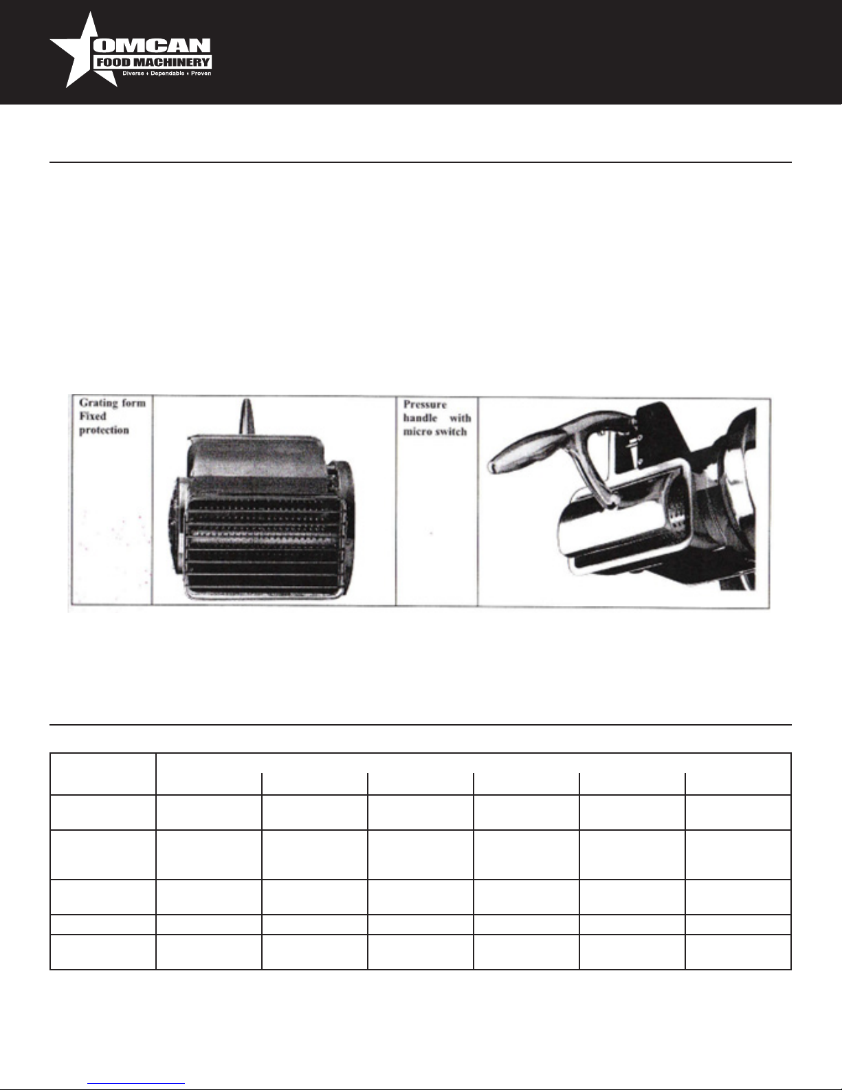
The machine transmission parts are completely isolated by means of xed protections which do not allow
access improper objects. For all safety functions including the control and check systems, well-tested
components and safety principles have been used.
Grater group:
1. Taking into account the machine’s modality and use, the moving elements are not isolated from the
protections and safety devices,
2. On the handle and pressure group, a micro switch is placed, which stops the grater roll rotation so it is
possible to access the grater mouth,
3. Fingers are prevented from accessing the grater roll as there is a xed protection piece to stop this.
ONE YEAR WARRANTY
Technical Specications
TECHNICAL
DATA
Motor Power
(kW / HP)
Grater Mouth
Internal Size
(mm)
Grater Timetable
production (kg/h)
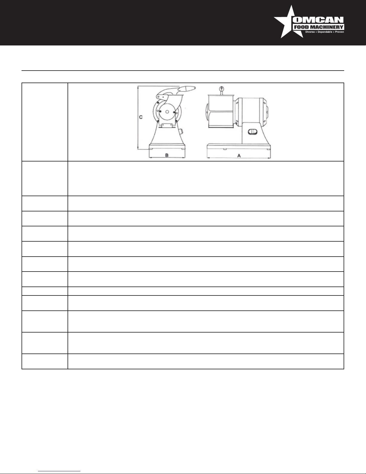
Mass (kg) 17 17 20 17 20 40
Maximum Size: A
x B x C (mm)
GS G8D GSM G1 GD GG
0.75 / 1 0.75 / 1 1.1 / 1.5 0.75 / 1 0.75 / 1 3 / 4
140 x 75 140 x 75 140 x 75 140 x 75 140 x 75 x 2 285 x 150
50 50 50 50 50 100
380 x 220 x 380 380 x 220 x 380 420 x 220 x 380 410 x 220 x 350 540 x 220 x 380 700 x 400 x 600
MODEL
7
Page 8
Technical Specications
Continue
Acoustic
Power Level
Considered
Equal to A
Current Nature -
Frequency
Full Charge
Current
Use Nominal
Voltage
Auxilary Circuits
Voltage
Mass and
Neutral
Protection
Degree
Use Place Inside
Machine
Positioning
Max
Environment Air
Temperature
Requested
Minimum
Illumination
Product Directive
Conformance
Working ground used in the food eld of height included between 900/1100mm from the trampling level of
adequate capacity, with a free circulation space of at least 800mm
98/37/CE, 73/32/CEE and successive modications and integrations, Reg. 1935/2004
Minor of 70dBA
Cfr. Machine Plate
Cfr. Machine Plate
Cfr. Machine Plate
AC 24V - DC 24V
TT e TN
IP X3
+40°C
500 lux
8
Page 9
Technical Specications
GROUP
GS G8D GSM G1 GD GG
Basic machine body, grater on the left ● ● ● ●
Basic machine body, grater on the right ● ● ●
Increased motor ●
Motor from 3 kW ●
Hulled machine body (I) ●
Stamped grater roll ● ● ● ● ● ●
Milled grater roll ● ● ● ● ●
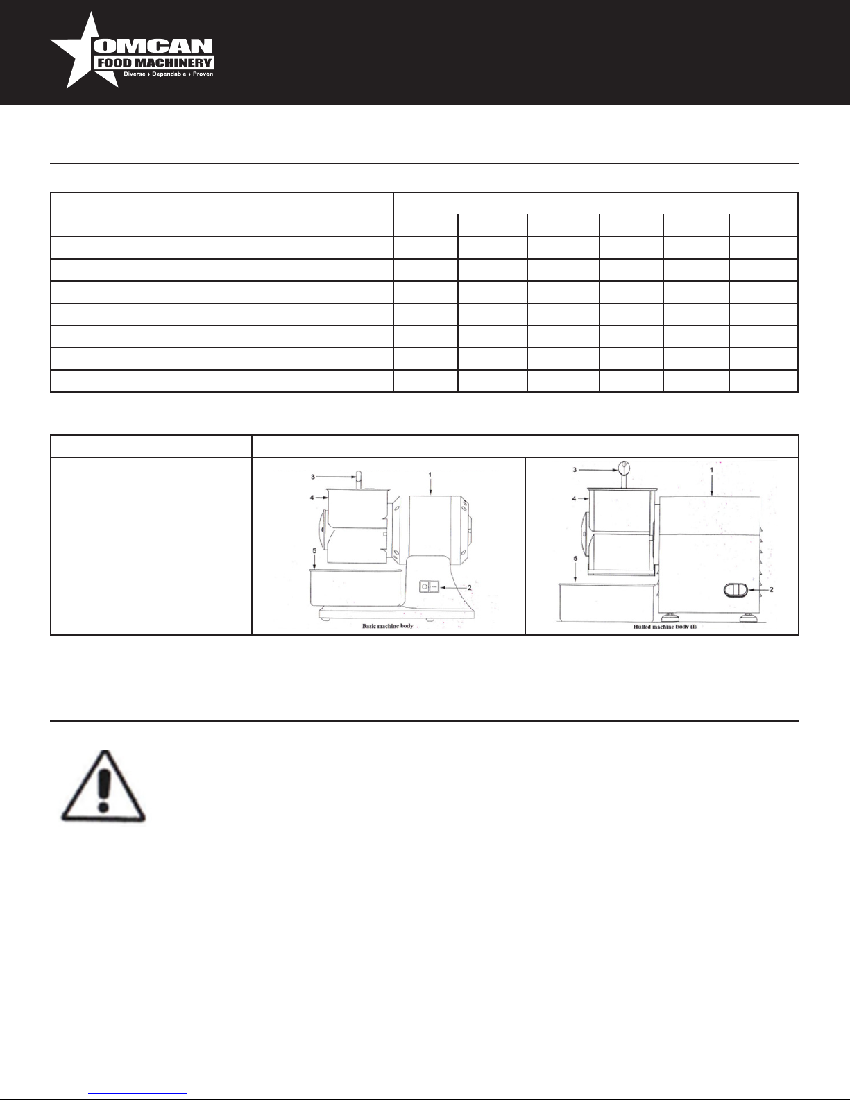
GROUP EXAMPLE
1. Machine Body
2. Control Switch ON/OFF
3. Pressure Handle
4. Grater Mouth
5. Collect Container
MODEL
The machine management is allowed only by authorized personnel and those of a sufcient
technical experience.
Before switching on the machine perform the following operations:
• Read with attention the technical documentation.
• Know what protections and emergency devices are available on the machine, their
location and functioning.
The non-authorized use of commercial parts and accessories altering the protections and safety devices can
cause some malfunctions and danger for the operators. The operator must have received adequate training.
WORKING POSITIONS AND OPERATORS TASKS
As described in the instructions manual, the machine is designed to be drive by an operator skilled and
informed on the residual risks with competency and in a safe manner.
Installation and Operation
9
Page 10

Installation and Operation
The normal working zone of the operator is:
1. The machine’s frontal zone near the grater mouth (dened loading zone) in normal conditions of functioning
is the loading operations of the food product, with the xed covers closed and blocked;
2. The machine’s front, the product dispenser in normal conditions of functioning is the location for withdrawal
operations of the food product stored in the collect container, with the xed covers in closed and blocked
position.
TRANSPORTATION, HANDLING AND STORING
All transportation and handling operations must be performed by informed and trained personnel and must
have read and understood the safety instructions shown in this manual.
1. Perform the machine handling and transportation always when it is off;
2. Verify that lifting means are use, it is able to support the loading weight and overall
dimensions in safety conditions and that are approved and subjected to a regular
maintenance,
3. Adopt all necessary measures to assure the maximum stability in relation to their mass,
4. Avoid making the machine suffer shaking or accidental collisions during the moving and
the loading,
5. Perform the handling with continual movements, without pulls or repeated impulses.
PACKING REMOVAL – OPENING MODALITY
PACKING DESCRIPTION – HOW TO GET RID OF THE PACKING MATERIAL
The machines are package so that the liquids inside and organic matters are not present. There is a
polyethylene cover around the machine which is then inserted in a cardboard box of adequate size. The empty
spaces within the box are occupied with ll material.
Do not waste the packaging, but store it for possible transportation or locate a recycling agency for disposal.
It is an employer’s obligation to be acquainted of the laws in its own country and observe these legislations. It
is forbidden and liable to nes to leave the machine and electric equipment in the environment.
PREPARATION PRELIMINARY OPERATIONS
STABILITY
The machine stability is designed so that in normal functioning conditions, taking into account the climatic
conditions, the machine can be used without reversal risk, fall or inopportune movement. Taking into account
the conformation and the position of the machine, it will function without fastening it to the working ground.
GRATER ROLL ROTATION
The operations indicated must be performed by the maintenance person (skilled personnel
in the electric maintenance eld of industrial machinery). For machines fed with three phase
voltage (3 PE AC 400V 50Hz), slacken lightly the blockage wheel to not have a strong
10
Page 11

Installation and Operation
pressure on the drilled plate for the cutting knife. When turning on, verify the Archimedean screw / grater
roll rotates counterclockwise. If there is clockwise rotation, switch off the machine, disconnect the plug,
disassemble it, disconnects the two phase conductions and invert their position.
FUNCTIONING DESCRIPTION
The control devices are designed and manufactured to handle normal service stresses and strains. The control
devices are clearly visible, locatable and marked distinctly. The main control devices are shown:
TYPE / COLOUR REFERENCE / DESCRIPTION
Button / Black “0” / button for the machine stop control
Button / White “1” / button for the machine start control
STARTING
The machine only starts with a voluntary action on the control device: white button “1” for the starting control.
STOP
For the stop control push the black button “0”. In case of momentary or extended stop, all food products must
be removed to get the machine to function again.
FUNCTIONING SAFETY
If the machine is under stress or is exposed to long functioning times or overload, the thermal protection
function will stop the machine. In this case, wait until it is completely cooled before proceeding to the starting
function.
VOLTAGE LACKING
In the case of the electric feeding breaking off of the machine and being disconnected, the machine will only
restarted after the electric feeding is back or there is re-connection to the power source.
STARTING
The machine only starts with a voluntary action on the control device: white button “1” for the starting control.
STOP
For the stop control push the black button “0”. In case of momentary or extended stop, all food products must
be removed to get the machine to function again.
FUNCTIONING SAFETY
If the machine is under stress or is exposed to long functioning times or overload, the thermal protection
function will stop the machine. In this case, wait until it is completely cooled before proceeding to the starting
function.
VOLTAGE LACKING
In the case of the electric feeding breaking of if the machine is disconnected, the machine will only be restarted
after the electric feeding is back or there is re-connection to the power source.
11
Page 12

Installation and Operation
PRESSURE OPENING
Lifting the handle of the grater mouth stops the machine immediately because of the safety micro switch
function. The machine can be restarted by lowering the handle and closing the mouth of the machine.
CONTROLS AND VERIFICATIONS BEFORE STARTING
VERIFICATION / CONTROL MODALITY AND CHECKS
Check that:
• Extraneous objects aren’t on the machine, inside the
grater mouth and in dispensing zone of the grated
product.
Check the cleaning:
• Of the grater mouth, of the pressure and grater roll.
• The external surface of the machine.
Check the integrity:
• Of the xed protections.
• Of the machine body, grater mouth, pressure and the
grater roll.
Check the functionality:
• Of control system parts / control about the safety.
• Of the control devices.
Check the presence:
• Of strange noises.
• Of oil trails on the ground and on the Archimedean
screw.
Visually check the indicated parts, check if
objects or extraneous objects around the
machine. Make sure there is not food product left
over. In case of its presence, remove them.
Visually check all parts and surfaces to verify
their cleaning. Disassemble to check internal
parts. In case of mold or other types of dirtiness,
follow the cleaning procedures indicated in
chapter 5.
All xed protections must perform their function.
Verify the integrity of the external surface. The
parts must be replaced at rst sight of erosion or
breaking.
All devices must perform desired function. The
actuators and all parts must be changed at rst
sight of erosion or breaking.
If there are strange noises, for example a seizing
of mechanical break, stop immediately and
contact maintenance personnel. Check during
work and at the end of every use. Check if there
are oil trails present. If there are any uid drops,
stop immediately and contact maintenance
personnel.
Possible changes in parts must happen with manufacturer original parts or at least of quality, safety and
equivalent characteristics. For analysis, contact the Authorized Assistance Center.
PUT IN FUNCTION
The machine operator can put in function the machine if:
1. Positive check of preliminary operations.
2. Positive check of electric feeding.
3. Connection in power socket.
4. For the functioning of the GRATER GROUP.
a. Positive check of the direction of grater roll rotation.
b. Positive check result and verications.
c. Concluded all checks and veried all safety instruments.
d. Place a gathering at the basin of the machine in correspondence of the food exit zone.
12
Page 13

Installation and Operation
e. Activate the machine using the control device, turn to “1”.
f. Introduce manually the food product within the grater mouth and drive it towards the grater roll by
lowering the pressure roll.
g. At the end of the food product introduction, or when there is no room left in the basin, stop the machine
using the control device, turn to “0”.
It is recommended to not use the machine without food product.
SWITCHING OFF
Switching off the machine is completed as follows:
1. Before switching off, wait until all food has exited the machine.
2. Stop the machine by using the control device and switching it to “0”.
3. Disconnect the machine plug from the feeding socket.
4. Perform the cleaning interventions.
UNBLOCK IN CASE OF OBSTACLE
During the normal function of the machine, introduction of hard and dry products could block the machine. The
same result can occur if the electric feeding is broken. To be able to resume normal function, the blocked food
product must be removed manually or the power cable is restored.
Maintenance
MAINTENANCE PERSONNEL REQUIREMENTS
The term “maintenance” is not only periodic checks but also the analysis of all problems that put the machine
out of service. It is essential that for the maintenance, cleaning, parts change and breaks research, these
actions are to be entrusted to a skilled personnel authorized by the employer. All operations of maintenance,
cleaning and parts change, must be performed with the machine completely stopped and free of external
feeding sources.
MAINTENANCE PRESCRIPTIONS
PROTECTIONS REMOVAL AND/OR PROTECTION DEVICES
For any interventions described in present chapter, it is necessary to remove the xed protections. The removal
can only happen by a trained maintenance personnel. At the end of the intervention, these protections must
be replaced to their original position and fastened correctly. The maintenance must disconnect the machine
completely before proceeding with the removal of the xed protection.
BREAKS OR DAMAGES RESEARCH AND MOVING ELEMENTS UNBLOCKING
13
Page 14

Maintenance
The following indicates the interventions for the breaks or damages search and moving elements unblocking
which can be performed by maintenance personnel.
EXTRAORDINARY MAINTENANCE
In the event of breaks, revisions, mechanical and electrical damages, it is necessary to directly contact Omcan.
The instructions for extraordinary maintenance does not appear in the instruction manual and must be explicitly
requested to the manufacturer.
CLEANING
PLEASE UNPLUG THE UNIT BEFORE CLEANING
Warning: It is forbidden to clean the machine while the grater or any grating part is working. Please make sure
to empty and unplug the grater before starting the cleansing procedure.
Cleansing frequency: Please clean the grater at the end of each food processing cycle or on a daily basis.
Cleansing procedure: Please make sure you follow the below-mentioned cleansing procedure when cleaning
all those parts that come in contact with food (i.e. pressure handle, cheese grater mouth and grating roll) and
the grater case.
• Use a hard-bristled brush to remove any cheese residual from the roll teeth.
• Peel off all the cheese leftovers with scrapers.
• Dip a clean cloth in hot water mixed with neutral soap, and wring it out. Clean with this damp cloth the
grater case and the grating parts (i.e. cheese grater mouth and grating roll). You can also use some dish-
washing soap. To take off greasy use denatured alcohol. When using specic products for stainless steel
cleansing, please make sure they are liquids. DO NOT USE creamy or abrasive products. DO NOT USE
products that contain CHLORINE. DO NOT USE any type of water jet to clean this unit.
The machine, electrical equipment and machine board components must never be washed using water or with
any kind of jets. Do not ever put the machine directly in the sink or under water. The machine hygiene level and
the associated equipment is in conformance with applicable international standards requirements, but requires
disassembly for the cleaning.
14
Page 15

FREQUENCY PERSONNEL MODALITY
At the end of
every shift
of work and
before the daily
use
Operator PERIODS OF LONG INACTIVITY
During long inactive periods pass over all steel surfaces (especially if
stainless) with clothes soaked in Vaseline oil to spread a protective veil.
PRODUCTS NOT TO USE
• Compressed air with jets towards the zones where food comes in
contact and in the general direction of the machine.
• Vapor equipment, detergent that contains CLORO (also if diluted)
or its compounds such as: bleach, muriatic acid, marble cleaning,
general decalcifying, products to clear the drain, etc. They can
attack steel, staining and oxidizing is unavoidable. The described
products can oxidize and corrode steel.
• Steel wool, brushes or abrasive discs produced with other metals or
alloys or tools that have previously cleaned other metals or alloys.
• Detergents in abrasive dust.
• Fuel, solvents or ammable and/or corrosive uids.
• Substances used to clean silver.
Maintenance
Troubleshooting
TYPE POTENTIAL
CAUSES
Net voltage lacking General black out. Contact the electric distributor.
Fuses or magneto
thermals intervention
place upstream of the
machine feeding line.
Functioning
intervention
Protection device
intervention inside
the machine.
Grater handle lifted. The machine can be restarted by lowering the handle and
Cause(s) not
identiable.
MODALITY AND COMPARISONS
After having eliminated the causes that have caused
intervention in the protection device, restore it. If the problem
persists, contact an electrician.
Contact an electrician. After having eliminated the causes
of the intervention, restore it. In case of fuses intervention,
change them with types of the same model, calibration and
intervention curve.
closing the mouth of the machine.
Direction contact Omcan.
15
Page 16

Troubleshooting
The machine
doesn’t function:
the Archimedean
screw or grater roll
does not rotate
Feeding voltage
lacking.
Sectioning devices
set on “OFF”.
Intervened fuses
or non-functioning
magento thermals.
Start button is not
responding.
Thermal intervention
due to overheating.
Damaged micro
switch.
Check and restore the electric energy.
Turn the sectioning device to the “ON” position.
Change the intervened fuses, check the magneto thermal
switches state.
Check the START button efciently and if problem persists
contact Omcan.
Wait until completely cooled before restarting the machine.
Directly contact Omcan.
16
Page 17

Model FGM111 11401
Parts Breakdown
17
Page 18

Parts Breakdown
Model FGM111 11401
Position Description Position Description Position Description
1 Screw 5x25 (4 pcs.) 13 Cable with Plug Mod. Schuko V.230 26 Mouth Grattugia Mignon
2 Cap Motor Low 14 Screw 3,5 x9, 5 27 Screw 6x12 (2 pcs.)
3 Bearing 6004 ZZ 15 Cable from 12 28 Cheese Box
4 Spinetta DA 4x10 16 Condenser 12.5 uF 29 Roller Flange Burglary
5 Crankshaft V.230/50Hz 17 Closure of Protection 30 Roller Grattugia Mignon
6 Rotor 18 Screw 3,5 x9, 5 (2 pcs.) 30 Roller Grattugia Miniature Steel
7 Stator V.230/50Hz 19 Clamp for Condenser 31 Roller Flat Flange
7 Stator with Thermal V.230/50Hz 20 Screw 8x20 (2 pcs.) 32 Washer, 8x32x2, 5
8 Motor Housing 21 Switch 33 Screw 8x20
9 Bearing 6202 ZZ 22 Aluminum Base 34 Disc Locking ABS DA 80 mm.
10 Disc Locking ABS DA 80 mm. 23 Nut DA 8x15 (2 pcs.) 35 Screw 3,5 x9, 5 (2 pcs.)
11 Screw 3,5 x9, 5 (2 pcs.) 24 Stud Threaded 8x55 36 Gasket Base
12 Rubber Feet (4 pcs.) 25 Miniature Aluminum Lever Grattugia
13 Cable with Plug 25 Lever Grattugia Mignon with Insert
18
Page 19

Model FGM111M 21719
Parts Breakdown
19
Page 20

Parts Breakdown
Model FGM111M 21719
Position Description Position Description Position Description
1 Screw 5x25 (4 pcs.) 16 Sheet V.230/50Hz 31 Screw 3x12 (2 pcs.)
2 Cap Motor Low 17 Feet Adhesive Sheet (4 pcs.) 32 Micro Switch Magnetic
3 Bearing 6004 ZZ 18 Closure of Protection 33 Mouth Grattugia Mignon
4 Spinetta DA 4x10 19 Screw 3,5 x9, 5 (2 pcs.) 34 Rivets (3 pcs.)
5 Crankshaft V.230/50Hz 20 Clamp for Condenser 35 Grille
6 Rotor 21 Condenser 12.5 uF 36 Cheese Box
7 Stator V.230/50Hz 22 Screw 8x20 (2 pcs.) 37 Screw 6x12 (2 pcs.)
7 Stator with Thermal V.230/50Hz 23 Switch 38 Roller Flange Burglary
8 Motor Housing 24 Aluminum Base 39 Screw 5x40
9 Bearing 6202 ZZ 24 Base ABS 40 Roller Grattugia Mignon
10 Disc Locking ABS DA 80 mm. 25 Magnet Holder 40 Roller Grattugia Miniature Steel
11 Screw 3,5 x9, 5 (2 pcs.) 26 Wheat 5x6 41 Flangia Rullo Piatta
12 Rubber Feet (4 pcs.) 27 Gasket Base 42 Washer, 8x32x2, 5
13 Cable with Plug 28 Pin from 8x60 43 Screw 8x20
13 Cable with Plug Mod. Schuko V.230 29 Wheat 6x6 44 Disc Locking ABS DA 80 mm.
14 Screw 3,5 x9, 5 30 Miniature Aluminum Lever Grattugia 45 Screw 3,5 x9, 5 (2 pcs.)
15 Cable from 12 30 Lever Grattugia Mignon with Insert
20
Page 21

Model FGS101 11402
Parts Breakdown
21
Page 22

Parts Breakdown
Model FGS101 11402
Position Description Position Description Position Description
1 Screw 4x8 (2 pcs.) 13 Screw 8x22 (2 pcs.) 29 Screw 5x30 (4 pcs.)
2 Closing Disc ABS 100 mm. 14 Cheese Box 30 Screw 4x8 (2 pcs.)
3 Screw Fixing Roller 10x35 15 Screw 5x30 (4 pcs.) 31 Disc Locking ABS DA 80 mm.
4 Washer 10x30x2 16 Shell with Hub 32 Cable with Plug Mod.Schuko V.230
5 X Flange Standard Roller 17 Bearing 6205 2RS 32 Cable with Plug Mod.Schuko V.400
5 X Flange Steel Roller 18 Spinetta Stainless Steel 4x10 33 Screw 4x8
6 Grater Punched 19 Crankshaft 34 Gland PG9/11
6 Roller Grattugia Milled 20 Rotor 35 Bipolar Switch
6 Roller Scratched Steel with Flange 21 Stator V.230/50Hz 4 Poles 35 Switch Pole
7 X Flange Standard Roller 21 Stator V.400/50Hz 4 Poles 36 Condenser 16 uF
7 X Flange Steel Roller 22 Motor Housing Open 37 Screw 4.8 x12 (4 pcs.)
8 Mouth Grattugia 23 Steel Band Short 38 ABS Seat
9 Screw 5x45 24 Rivets (4 pcs.) 39 Screw 8x25 (2 pcs.)
10 Pin from 8x57 25 Fan 40 Rubber Feet (4 pcs.)
11 Wheat 6x6 26 Fixing Ring Fan 41 Base
12 Lever Aluminum Grating 27 Bearing 6203 ZZ 42 Gasket Base
12 Grattugia Lever with Insert 28 Cap Fan
22
Page 23

Model FGS121 11403
Parts Breakdown
23
Page 24

Parts Breakdown
Model FGS121 11403
Position Description Position Description Position Description
1 Screw 4x8 (2 pcs.) 13 Mouth Grattugia 29 Cap Fan
2 Closing Disc ABS 100 mm. 14 Cheese Box 30 Screw 5x30 (4 pcs.)
3 Screw Fixing Roller 10x35 15 Screw 5x30 (4 pcs.) 31 Disc Locking ABS DA 80 mm.
4 Washer 10x30x2 16 Shell with Hub 32 Screw 4x8 (2 pcs.)
5 X Flange Standard Roller 17 Bearing 6205 2RS 33 Gasket Base
5 X Flange Steel Roller 18 Fixing Ring Fan 34 Bipolar Switch
6 Grater Punched 19 Fan 34 Switch Pole
6 Roller Grattugia Milled 20 Spinetta Stainless Steel 4x10 35 Rubber Feet (4 pcs.)
6 Roller Scratched Steel with Flange 21 Gland PG9/11 36 Base
7 X Flange Standard Roller 22 Crankshaft 37 Screw 8x25 (2 pcs.)
7 X Flange Steel Roller 23 Rotor 38 Condenser 25 uF
8 Screw 5x45 24 6 Pole Stator V.230/50Hz 39 ABS Seat
9 Pin from 8x57 24 6 Pole Stator V.400/50Hz 40 Screw 4.8 x12 (4 pcs.)
10 Wheat 6x6 25 Long Fan Housing 41 Screw 4x8
11 Lever Aluminum Grating 26 Steel Band Fan 42 Cable with Plug Mod.Schuko V.230
11 Grattugia Lever with Insert 27 Rivets (4 pcs.) 42 Cable with Plug Mod.Schuko V.400
12 Screw 8x22 (2 pcs.) 28 Bearing 6203 ZZ
24
Page 25

Model FGSM10 11404
Parts Breakdown
25
Page 26

Parts Breakdown
Model FGSM10 11404
Position Description Position Description Position Description
1 Screw 4x8 (2 pcs.) 16 Micro Switch Mechanical 35 Bearing 6203 ZZ
2 Closing Disc ABS 100 mm. 17 Mouth Grattugia 36 Cap Fan
3 Screw Fixing Roller 10x35 18 Rivets (3 pcs.) 37 Screw 5x30 (4 pcs.)
4 Washer 10x30x2 19 Screw 8x22 (2 pcs.) 38 Disc Locking ABS DA 80 mm.
5 X Flange Standard Roller 20 Grille 39 Screw 4x8 (2 pcs.)
5 X Flange Steel Roller 21 Cheese Box 40 Base
6 Grater Punched 22 Screw 5x30 (4 pcs.) 41 Keyboard 24V
6 Roller Grattugia Milled 23 Shell with Hub 42 Rubber Feet (4 pcs.)
6 Roller Scratched Steel with Flange 24 Bearing 6205 2RS 43 Screw 8x25 (2 pcs.)
7 X Flange Standard Roller 25 Spinetta Stainless Steel 4x10 44 Condenser 16 uF
7 X Flange Steel Roller 26 Crankshaft 45 Sheet Low Voltage 24V V.230
8 Screw 5x45 27 Rotor 45 Sheet Low Voltage 24V V.400
9 Pin from 8x57 28 Gland PG9/11 46 Screw 4x8
10 Lever Aluminum Grating 29 Stator V.230/50Hz 4 Poles 47 Cable with Plug Mod.Schuko V.230
10 Lever Grater with Insert 29 Stator V.400/50Hz 4 Poles 47 Cable with Plug Mod.Schuko V.400
11 Rivets (2 pcs.) 30 Motor Housing Open 48 Feet Adhesive Sheet (4 pcs.)
12 Micro Switch Cover 31 Steel Band Short 49 ABS Seat
13 Nottolino 32 Rivets (4 pcs.) 50 Screw 4.8 x12 (4 pcs.)
14 Wheat 6x6 (2 pcs.) 33 Fan 51 Gasket Base
15 Screw 2.8 x15 (2 pcs.) 34 Fixing Ring Fan
26
Page 27

Model FGSM15 11405
Parts Breakdown
27
Page 28

Parts Breakdown
Model FGSM15 11405
Position Description Position Description Position Description
1 Screw 4x8 (2 pcs.) 16 Micro Switch Mechanical 35 Bearing 6203 ZZ
2 Closing Disc ABS 100 mm. 17 Mouth Grattugia 36 Cap Fan
3 Screw Fixing Roller 10x35 18 Screw 8x22 (2 pcs.) 37 Screw 5x30 (4 pcs.)
4 Washer 10x30x2 19 Grille 38 Disc Locking Abs DA 80 mm.
5 X Flange Standard Roller 20 Rivets (3 pcs.) 39 Screw 4x8 (2 pcs.)
5 X Flange Steel Roller 21 Cheese Box 40 Gasket Base
6 Grater Punched 22 Screw 5x30 (4 pcs.) 41 Keyboard 24V
6 Roller Grattugia Milled 23 Shell with Hub 42 Rubber Feet (4 pcs.)
6 Roller Scratched Steel with Flange 24 Bearing 6205 2RS 43 Base
7 X Flange Standard Roller 25 Fixing Ring Fan 44 Screw 8x25 (2 pcs.)
7 X Flange Steel Roller 26 Fan 45 Condenser 25 uF
8 Screw 5x45 27 Spinetta Stainless Steel 4x10 46 ABS Seat
9 Pin from 8x57 28 Gland PG9/11 47 Feet Adhesive Sheet (4 pcs.)
10 Wheat 6x6 (2 pcs.) 29 Crankshaft 48 Sheet Low Voltage 24V V.230
11 Lever Aluminum Grating 30 Rotor 48 Sheet Low Voltage 24V V.400
11 Lever Grater with Insert 31 6 Pole Stator V.230/50Hz 49 Screw 4.8 x12 (4 pcs.)
12 Micro Switch Cover 31 6 Pole Stator V.400/50Hz 50 Cable with Plug Mod.Schuko V.230
13 Rivets (2 pcs.) 32 Long Fan Housing 50 Cable with Plug Mod.Schuko V.400
14 Nottolino 33 Steel Band Fan 51 Screw 4x8
15 Screw 2.8 x15 (2 pcs.) 34 Rivets (4 pcs.)
28
Page 29

Model FGM111 11401
Electrical Schematics
29
Page 30

Electrical Schematics
Model FGM111M 21719
30
Page 31

Model FGS101 11402
Electrical Schematics
31
Page 32

Electrical Schematics
Model FGS121 11403
32
Page 33

Model FGSM10 11404
Model FGSM15 11405
Electrical Schematics
33
Page 34

34
Page 35

Warranty Registration
Thank you for purchasing an Omcan product. To register your warranty for this product, complete the information below, tear off the card at
the perforation and then send to the address specied below. You can also register online by visiting:
www.omcan.com/warrantyregistration.html
For mailing in Canada For mailing in the US
OMCAN INC.
PRODUCT WARRANTY REGISTRATION
3115 Pepper Mill Court,
Mississauga, Ontario
Canada, L5L 4X5
PRODUCT WARRANTY REGISTRATION
1889 Maryland Avenue,
Niagara Falls, New York
OMCAN
USA, 14305
Purchaser’s Information
Name: Company Name:
Address:
Telephone:
City: Province or State: Postal or Zip: Email Address:
Country: Type of Company:
Restaurant Bakery Deli
Dealer from which Purchased: Butcher Supermarket Caterer
Dealer City: Dealer Province or State: Institution (specify):
Invoice: Other (specify):
Model Name: Model Number: Serial Number:
Machine Description:
Date of Purchase (MM/DD/YYYY): Date of Installation (MM/DD/YYYY):
Thank you for choosing Omcan
35
Page 36

Over the last 60 years, Omcan has grown to become a leading supplier to the food
service industry in Canada and the USA. Our success over these many years is
directly attributed to our established relationships with all of our valued customers
and through providing them with Diverse, Dependable and Proven products.
Omcan continues to help our customers remain competitive.
With associates in North America, Europe, and Asia, our global footprint continues
to expand as we hold to the principle that clients benet from the accessibility
and familiarity of our sales team. In 2013 as our geography and brand recognition
continued to grow, we changed to one name Omcan Food Machinery.
In over 200,000 sq ft of warehouse space we stock over 2,500 quality food
equipment and supplies for the food preparation market.
 Loading...