

Page 1
B I R O
MODEL F2000/3000/4000/3000HD/B1200
OPERATION & SERVICE MANUAL
PARTS LIST
GENERAL INSTRUCTIONS
* IMPORTANT SAFETY NOTICE *
This Manual contains important
safety instructions which must
be strictly followed when using
this equipment.
Item No.
###6-09-1
Page 2

TABLE OF CONTENTS
INTRODUCTION Page
Warranty………………………………………………………….
Reliability…………………………………………………………
GENERAL TECHNICAL FEATURES
Description………………………………………………………..
Main features……………………………………………………..
Safety devices…………………………………………………….
Components description………………………………………….
Overall measurements……………………………………………
INSTALLATION
Packing check…………………………………………………….
Placing the machine………………………………………………
Electrical connections…………………………………………….
Control panel……………………………………………………..
Operating test…………………………………………………….
UTILITY
Loading the automatic paper attachment…………………………
Product thickness regulation………………………………………
Loading the product and use………………………………………
CLEANING AND HYGIENE
Complete cleaning…………………………………………………
Disassembly of the removable accessories………………………...
Disassembly of the paddle…………………………………………
Disassembly of the hopper…………………………………………
Disassembly of the conveyor belt………………………………….
Disassembly of the regulation drum……………………………….
Disassembly of the scraper…………………………………………
Cleaning of the disassembled components…………………………
Assembly of the accessories………………………………………..
MAINTENANCE
Ordinary maintenance………………………………………………
SPARE PARTS LIST
Page 3

Wiring diagrams……………………………………………………
WARRANTY
The installation, the starting and the functioning of the machine must be effected by skilled
personnel only, who knows the machine. The personnel assigned to the assistance and
maintenance must always follow the instructions contained in the manual. The patty
forming machine must be used by trained personnel only. If necessary provide for the
personnel’s training, to learn the usual operations in order to assure the correct use of the
machine.
ABM disclaims all responsibility in case of:
Assembly of the
components of the machine and the electric connection not effected according to
the established rules;
Improper use of the
machine;
Tampering the
controls or the security protection;
Use of non-original
spare parts;
The warranty does not cover the normal use of the parts.
RELIABILITY
In case of improper use of the machine, it is possible to get injuries and accidents.
The patty forming machine must be used only by the personnel who must know the
machine and the content of the manual:
Make sure that
unskilled personnel – and especially children – do not operate the machine;
Do not modify or
remove the safety devices (covers and protections);
Use the machine
with concentration avoiding distractions;
Before cleaning and
maintenance, always disconnect the machine from the supply system;
Page 4

Periodically check
the main supply wire, in case of breaks or bad functioning, provide for the
replacement by skilled personnel.
Stop the machine
whenever it makes strange noises during the functioning;
Always keep the
working area clean and dry;
Do not deal with the
repairs if you are not able to eliminate the possible breakdowns, but contact the
technical assistance;
The machine is made
of accessories and parts especially designed in order to reduce the maintenance and
minimum.
GENERAL TECHNICAL FEATURES
Description
The ABM Patty
Forming machine is characterized by:
Compactness and
small overall measurements and with special features, able to satisfy the producing
requirements of both the great and the small distribution;
Reliability and safety
in the operation and the cleaning processes;
Hygiene of the parts
in contact with the product through the use of innovative materials conformed to the
current regulations;
Precision and
compactness of the finished product;
Strength, easy use,
controls and working stationing especially designed to optimize ergonomics.
Main Features
The castings are
made of anticorrodal thermically treated with innovative material for food, while all
the other components have been made of stainless steel. These parts are particularly
fit to resist the corrosive agents of the products used and are in conformity with the
hygienic regulations for food;
Page 5

The moving parts are
started by an electronic motor and the movement transmission operates through a
chain and mechanism;
The hopper, the
paddle, the conveyor belt, the drum and the accessories are easily disassembled to
effect a regular cleaning.
The thickness of the
product is adjustable;
The quantity of the
hamburgers produced per hour can be varied on request in the models with current
continue motors;
The hopper and the
moving of the product operate in a continuous way and this allows a homogenous
dough;
The controls are
easily identifiable and suitable to prevent accidental starting;
The transmission
parts are located inside the crankcase;
The machine is
equipped with a device which allows the cleaning of the roll during functioning
(scraper) and permits the separation of the products;
Different drums are
available, suitable o the forming of products with different shapes;
On request, the
machine can be supplied with electrical motors of different tensions.
Safety Devices
The Patty Forming Machine is equipped with the following protection and safety devices:
Safety micromagnet
on the hopper;
Plastic cover servo-
assisted by a micromagnet;
Protection and front
cover of the removable parts;
Page 6

Handle of the paddle
optimized to avoid crushing and use of keys or particular tools;
Starting of the
machine through reverser for servo-assisted manual or automatic control;
Emergency button
Materials in
conformity with the food hygienic regulations and fit to guarantee the good
resistance to oxidation.
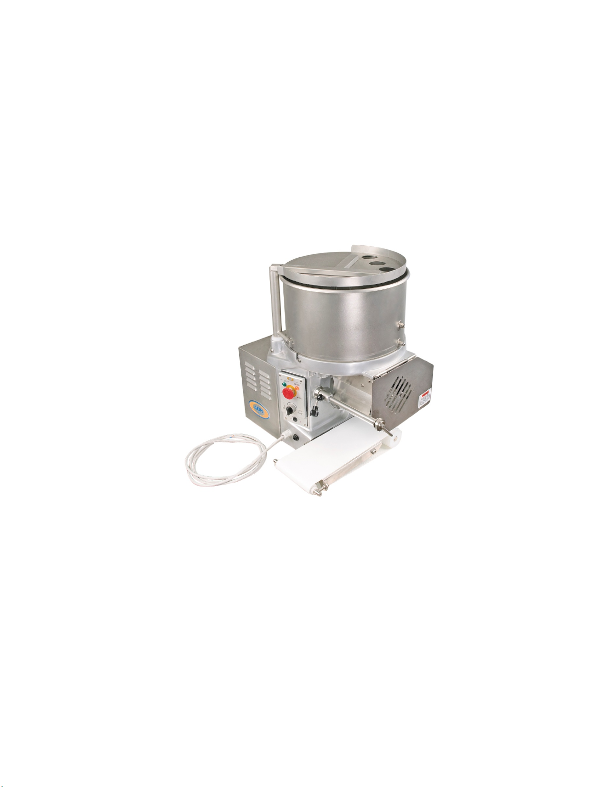
Components Description
CONTENTS
1. Cover
2. Hopper
3. Protection
4. Papering attachment
5. Drum stop ring nut
6. Drum
7. Scraper
8. Leading roll
9. Led roll
10. Conveyor belt
11. Footswitch
12. Speed variator for the mod. with current continuous
13. Manual/automatic switch
14. Stop button
15. Feeding signal light
16. Stop signal light
17. Transmission protection crankcase
18. Base
19. Cover shaft
Overall Measurements
F2000/4000
Length (A) 620
Width (B) 500
Page 7

Height (C) 610
Gross Created Weight – 72 kg.
Net Uncrated Weight – 67 kg.
Hopper capacity – 20 kg.
Optional Conveyor Belt – 1850 x 145
Hopper Power – see identification tag
Motor Power – see identification tag
Page 8

INSTALLATION
Packing Check
At the receipt of the machine, check the package to verify that the machine has not
been damaged.
The components of the package can be assimilated to the urban solid rubbish.
Placing the Machine
It is advisable to place the Patty Forming Machine on a stable working table
positioned on a height of about 800mm from the ground.
The installation area must allow the use of the machine in an optimal and
ergonomic way. It is advisable to place it in a dry, breezy place, far from warmth
sources; it can be used without any special arrangement of a normal working place.
Electrical Connections
The machine is equipped with a feeding wire. Before connecting it to the socket,
verify the functioning tension showed on the identification tag.
In case the details do not correspond, contact the distributor for the assistance
service.
The socket for the connection must correspond to the current rules.
Control Panel
Starting switch (automatic/manual) (1)
Red stop button (2)
Machine operating signal lamp (3)
Machine stop signal lamp (4)
Handle for speed regulation (5) (only for model at variable speed)
Note – in the Model F4000 the regulation of the speed and the quantity of hamburgers
is made by rotating the regulating handle with a quantity of products variable from… to a
maximum of 4000 pieces per hour.
Page 9

Operating Test
Before controlling the functionment, if you have not already done, you must
assemble the hopper, assemble the conveyor belt, close the cover and the front
protection.
Connect the footswitch, inserting the control pipe into the bush on the control
panel side.
Connect the plug to the socket.
Position the switch handle (1) on automatic.
Verify the rotation of the drum and the conveyor belt (see the arrow).
Verify the lighting of the light.
Push the stop button (2), the machine must stop and the light (3) must light up.
Position the switch handle (1) on manual.
Press the footswitch.
Verify the rotation of the drum and the conveyor belt (see the arrow).
Verify the lighting of the light.
Push the stop button (2). The machine must stop and the light (3) must light up.
During the functionment, when lifting the front plexi protection, the machine must
stop.
To continue, turn the operating switch again.
During the functionment, when rotating the hopper cover, the machine must stop.
To continue, turn the operating switch again.
UTILITY
To obtain good results you must use fitted meats and doughs. Arrange the machine with
all the accessories disassembled.
It is advisable not to use and let the machine function without any product in the
hopper.
Loading the Automatic Papering Attachment
Take out the papering attachment by pushing the button (I) and slipping it off
from the guide pins.
Replace the pushing spring.
Insert the paper block and take away the wrapper.
Reassemble the papering attachment in the guide pins, until the stop click.
Release the spring using the button placed under the papering attachment (2).
Page 10

Position the papering attachment, freeing the locking lever (3).
Regulate the center of the paper, turning the centering knob (4).
Product Thickness Regulation
The machine is regulated in the factory with a medium thickness; to obtain another
thickness, follow the instructions indicated below:
Take out the regulation drum by operating on the ring nut clockwise and taking
out the drum.
Loosen the stop knob of the gauging device (I).
Turn the gauging device, to regulate the thickness (2).
Lock the stop knob (1).
Reassemble the drum, inserting it in the guide shaft, until the stop click.
Loading the Product and Use
Open the cover and load the product in the hopper and close the cover again.
Connect the plug to the socket.
Start the machine: push the automatic switch (1).
Regulate the production speed with the regulation handle (2) (only for model with
selector).
During the functionment, operate intermittently, in order to clean the drum from
residual product.
The product will come down on the conveyor belt and will be moved to its end.
To stop the machine, operate on the stop button (I) or open the protections.
To continue, release the stop button and turn the start switch again (2).
CLEANING AND HYGIENE
Complete Cleaning
It is advisable to clean the machine daily or if necessary more frequently, in case it
was very dirty or after long periods of inactivity.
The cleaning must be carefully made for the parts in contact with the product.
Clean the structure of the machine with soft cloths, sponges, and rinse with water
frequently. Finally dry with soft and dry cloths.
Attention: the machine is not protected against steam throws, high pressure throws or
similar systems. In this case there is risk of short circuit or serious damages to the machine.
Disassembly of the Removable Accessories
Page 11

All the cleaning operations of the machine must always be done with the machine
not equipped with hopper, taking out the plug from the socket.
Disassembly of the Paddle
Hold the handle, turn anti-clockwise and lift.
To avoid accidents before disassembling, position the paddle away from the
hopper pins.
Disassembly of the Hopper
Open the cover completely.
Turn the hopper anti-clockwise, lift it and take it away from the base.
Disassembly of the Conveyor Belt
Lift the belt on the side of the return pulley.
Take off and disassemble the conveyor belt.
Disassemble the complete conveyor from the guide pin.
Disassembly of the Regulation Drum
Turn the stop ring nut anti-clockwise, pull the drum and disassemble it from the
control pin.
Disassembly of the Scraper
Loosen the stop knob of the scraper shaft.
Take off the complete scraper.
Cleaning of the Disassembled Components
All the disassembled components must be washed with warm water, neutral
detergent, rinsed in water and dried.
Assembly of the Accessories
To effect the reassembly of the accessories, proceed in the inverse way to what previously
described in the disassembly. Pay special attention to the assembly of the following
accessories:
Hopper: Insert the hopper with the two guides pins in the fusion taking care to
position the micromagnet on the side of the cover shaft and turn it until it hooks the
pins.
Paddle: position the inserting shaft of the paddle so that the pins in the hopper do
not overlap the paddle, then hold the paddle, put it on the shaft, making the shaft
plug coincide with the housing in the drum.
Drum: assembly the drum in the guide pin, making the shaft plug coincide with
the housing in the drum.
Page 12

MAINTENANCE
Ordinary Maintenance
The machine does not require a special maintenance for the regulations or replacements of
parts, but only requires a normal maintenance carried out by the operator which consists of
the following operations:
Verify the functionment of the micro-switches and of the electric buttons.
Verify the state of use of the feeding wire.
Whenever there was the necessity of repairs or special maintenance, contact the assistance
service or a qualified technician.
SPARE PARTS LIST
Wiring Diagrams
Models F2000 / F3000 / HD3000
Contents: TR = Transformer 0/115/230 – 0/24
K1 = Motor Contactor
PE = Emergency Button
MS1 = Security Microswitch
MS2 = Security Microswitch
MT = Motor
LE = Emergency Signal Lamp
LT = Tension Signal Lamp
TS = Signal Transection
Position A = Impulsive Function
Selector Functions: S1 Position Ø = Stopped Machine
Position B = Retentive Function
Model F4000
Contents: TR = Transformer 0/115/230 – 0/24
K1 = Motor Contactor
PE = Emergency Button
MS1 = Security Microswitch
MS2 = Security Microswitch
MT = Motor
Page 13

LE = Emergency Signal Lamp
LT = Tension Signal Lamp
TS = Signal Transection
Position A = Impulsive Function
Selector Functions: S1 Position Ø = Stopped Machine
Position B = Retentive Function
** Electric Diagram **
L1/MP = Feeding 220 Vac
T1/T2 = Start/Stop Board
Ø = Signal Lamps
1 = Emergency
3/4 = Security Switches
5 = Selector
6 = Automatic
7 = Foot Switch
Model 2000?
Electronic Card
(diagram)
Line 230 Vac L1 - L2
Motor 230 Vac 60 Hz U – V
Signal lamp
Start button
Stop Button
Security microswitch
K1 = Siemens mod. 3tk2031 Control switch (alternative)?
K2 = ABB mod. B63001 Control switch
U – V = Motor 230 Vac 60 Hz
F1 = Fuse 500 mA
T1 = Transformer 16Va pri
Page 14

RECOMMENDED SPARE PARTS
Page 15

HD3000
(drawing)
Page 16

(3 pages w/drawings)
Page 17

PNEUMATIC SPARE PARTS
 Loading...