

Page 1

Pasta Machine
Model PM-IT-0080
Item 13286
Instruction Manual
Revised - 08/21/2017
Toll Free: 1-800-465-0234
Fax: 905-607-0234
Email: service@omcan.com
www.omcan.com
Page 2

Table of Contents
Model PM-IT-0080
Section
General Information
Safety and Warranty
--------------------------------------------------------------------------- 3 - 4
--------------------------------------------------------------------------- 4 - 6
Technical Specications
Installation
Operation
Maintenance
--------------------------------------------------------------------------------------- 6 - 8
--------------------------------------------------------------------------------------- 8 - 11
--------------------------------------------------------------------------------- 11 - 13
Page
-------------------------------------------------------------------------- 6
Troubleshooting
Figure Drawings
Parts Breakdown
Electrical Schematics
Warranty Registration
----------------------------------------------------------------------------- 13 - 14
----------------------------------------------------------------------------- 14 - 21
---------------------------------------------------------------------------- 22 - 25
---------------------------------------------------------------------- 26 - 30
---------------------------------------------------------------------------- 31
2
Page 3

General Information
Omcan Manufacturing and Distributing Company Inc., Food Machinery of America, Inc. dba Omcan
and Omcan Inc. are not responsible for any harm or injury caused due to any person’s improper or
negligent use of this equipment. The product shall only be operated by someone over the age of 18, of
sound mind, and not under the inuence of any drugs or alcohol, who has been trained in the correct
operation of this machine, and is wearing authorized, proper safety clothing. Any modication to the
machine voids any warranty, and may cause harm to individuals using the machine or in the vicinity of
the machine while in operation.
CHECK PACKAGE UPON ARRIVAL
Upon receipt of an Omcan shipment please inspect for external damage. If no damage is evident on the
external packaging, open carton to ensure all ordered items are within the box, and there is no concealed
damage to the machine. If the package has suffered rough handling, bumps or damage (visible or concealed),
please note it on the bill of lading before accepting the delivery and contact Omcan within 24 hours, so we may
initiate a claim with the carrier. A detailed report on the extent of the damage caused to the machine must be
lled out within three days, from the delivery date shown in the shipping documents. Omcan has no recourse
for damaged products that were shipped collect or third party.
Before operating any equipment, always read and familiarize yourself with all operation and safety
instructions.
Omcan would like to thank you for purchasing this machine. It’s of the utmost importance to save
these instructions for future reference. Also save the original box and packaging for shipping the
equipment if servicing or returning of the machine is required.
---------------------------------------------------------------------------------------------------------------------------------------------------
Omcan Fabrication et distribution Companie Limité et Food Machinery d’Amerique, dba Omcan et
Omcan Inc. ne sont pas responsables de tout dommage ou blessure causé du fait que toute personne
ait utilisé cet équipement de façon irrégulière. Le produit ne doit être exploité que par quelqu’un de
plus de 18 ans, saine d’esprit, et pas sous l’inuence d’une drogue ou d’acohol, qui a été formé pour
utiliser cette machine correctement, et est vêtu de vêtements de sécurité approprié. Toute modication
de la machine annule toute garantie, et peut causer un préjudice à des personnes utilisant la machine
ou des personnes à proximité de la machine pendant son fonctionnement.
VÉRIFIEZ LE COLIS DÈS RÉCEPTION
Dès réception d’une expédition d’Omcan veuillez inspecter pour dommages externes. Si aucun dommage
n’est visible sur l’emballage externe, ouvrez le carton an de s’assurer que tous les éléments commandés
sont dans la boîte, et il n’y a aucun dommage dissimulé à la machine. Si le colis n’a subi aucune mauvaises
manipulations, de bosses ou de dommages (visible ou cachée), notez-le sur le bond de livraison avant
d’accepter la livraison et contactez Omcan dans les 24 heures qui suivent, pour que nous puissions engager
une réclamation auprès du transporteur. Un rapport détaillé sur l’étendue des dommages causés à la machine
doit être rempli dans un délai de trois jours, à compter de la date de livraison indiquée dans les documents
d’expédition. Omcan n’a aucun droit de recours pour les produits endommagés qui ont été expédiées ou cueilli
par un tiers transporteur.
3
Page 4

General Information
Avant d’utiliser n’importe quel équipement, toujours lire et vous familiariser avec toutes les opérations
et les consignes de sécurité.
Omcan voudrais vous remercier d’avoir choisi cette machine. Il est primordial de conserver ces
instructions pour une référence ultérieure. Également conservez la boîte originale et l’emballage pour
l’expédition de l’équipement si l’entretien ou le retour de la machine est nécessaire.
---------------------------------------------------------------------------------------------------------------------------------------------------
Omcan Empresa De Fabricacion Y Distribucion Inc. Y Maquinaria De Alimentos De America, Inc. dba
Omcan y Omcan Inc. no son responsables de ningun daño o perjuicío causado por cualquier persona
inadecuada o el uso descuidado de este equipo. El producto solo podra ser operado por una persona
mayor de 18 años, en su sano juicio y no bajo alguna inuencia de droga o alcohol, y que este ha sido
entrenado en el correcto funcionamiento de esta máquina, y ésta usando ropa apropiada y autorizada.
Cualquier modicación a la máquina anúla la garantía y puede causar daños a las personas usando la
máquina mientras esta en el funcionamiento.
REVISE EL PAQUETE A SU LLEGADA
Tras la recepcion de un envio Omcan favor inspeccionar daños externos. Si no hay daños evidentes en el
empaque exterior, Habra el carton para asegurararse que todos los articulos solicitados ésten dentro de la
caja y no encuentre daños ocultos en la máquina. Si el paquete ha sufrido un manejo de poco cuidado, golpes
o daños (visible o oculto) por favor anote en la factura antes de aceptar la entrega y contacte Omcan dentro
de las 24 horas, de modo que podamos iniciar una reclamación con la compañia. Un informe detallado sobre
los daños causados a la máquina debe ser llenado en el plazo de tres días, desde la fecha de entrega que se
muestra en los documentos de envío. Omcan no tiene ningun recurso por productos dañados que se enviaron
a recoger por terceros.
Antes de utilizar cualquier equipo, siempre lea y familiarizarse con todas las instrucciones de
funcionamiento y seguridad.
Omcan le gustaría darle las gracias por la compra de esta máquina. Es de la mayor importancia para
salvar estas instrucciones para futuras consultas. Además, guarda la caja original y el embalaje para el
envío del equipo si servicio técnico o devolución de la máquina que se requiere.
Safety and Warranty
• Read all warning labels applied to any part of the machine, and promptly replace them when they become
worn or illegible.
• Only trained and authorised personnel should operate the machine.
• If any part jams or locks up, before clearing make sure you rst switch off the motor. DO NOT clean, oil
or grease by hand any moving parts of the machine. In addition, all repair and setting operations of any
moving parts with the motor running, are prohibited, unless the necessary precautions to prevent any
accidents have been taken beforehand.
4
Page 5

Safety and Warranty
• All moving parts are tted with adequate guards and protections. Always remount them after removal for
servicing.
WEAR ADEQUATE CLOTHING
Be sure to wear tight-tting clothing without any loose parts. Never wear open or unfastened jackets, shirts or
overalls.
IMPORTANT
To prevent accidents and ensure best performance the machine must not be modied or altered unless
authorised by the manufacturer. Nor must it be used in conditions or for purposes other than those
for which it has been expressly designed. Any arbitrary modication implemented in this machine will
automatically exempt the manufacturer from any liabilities for ensuing damage or injury. This machine
has been designed and engineered in conformity to European directives 89/392 EC, 91/368 EC, 93/44
EC and 93/68 EC.
ELECTRICAL SHOCK
For your own personal safety, before connecting the machine to mains:
• Check that power mains leading to distribution socket is tted with an appropriate multipolar switch
protected against overloads and shortcircuits.
• Carry out all phase connections, as well as any neutral and ground connections (compulsory) with a
standard plug compatible with the above mentioned socket. The protection lead (ground) is the one
with the yellow/green insulating sheath; make sure that the power supply cable is appropriate to its use,
according to length, mains voltage and machine consumption.
• Unless adequate protections against electrical shock are tted, do not operate the machine in damp or wet
environments.
Strictly do not start up the machine without the protective panelling. This may jeopardise personnel
safety and machine serviceability.
1 YEAR PARTS AND LABOUR WARRANTY
Within the warranty period, contact Omcan Inc. at 1-800-465-0234 to schedule an Omcan authorized
service technician to repair the equipment locally.
Unauthorized maintenance will void the warranty. Warranty covers electrical and part failures, not
improper use.
Please see www.omcan.com/warranty.html for complete info.
WARNING:
The packaging components are classied as normal solid urban waste and can therefore be disposed of
without difculty.
In any case, for suitable recycling, we suggest disposing of the products separately (differentiated
waste) according to the current norms.
5
Page 6

Safety and Warranty
DO NOT DISCARD ANY PACKAGING MATERIALS IN THE ENVIRONMENT!
Technical Specications
Model PM-IT-0080
Tank Capacity 110 lbs. / 50 kgs.
Power for Worm 5.5 HP / 4.1 kW
Power for Paddle 2.5 HP / 1.86 kW
Output per Hour 176 lbs. / 80 kgs.
Electrical 208V / 60Hz / 3
Weight 948 lbs. / 430 kgs.
Dimensions 53.1” x 33” x 63” / 1350 x 840 x 1600mm
Item Number 13286
Installation
TRANSPORTATION AND HANDLING
The machine, pallet-mounted at origin, is shipped enclosed in appropriate packaging and strapped to the
wooden pallet itself. Apart from the machine, you can nd the operating instructions and the conformity
declaration to the EC 89/392 directive. The accessories furnished and the cutting groups must be put inside
the packing case, suitably wrapped and protected. When unloading the machine from the transport vehicle, lift
at the points marked on the packaging using suitable equipment. Unless you need to check the contents, you
are recommended not to open the packaging until the moment of installation. After opening the case, remove
packaging, straps, packaging and polystyrene strips. Dispose of this material according to the regulations
in force. Lift the machine and place on the installation site and take-away the support pallet, using a hoist of
appropriate capacity.
The lifting and positioning of the machine must be carried out by at least two people.
To position the machine denitively or when moving it for cleaning insert the tip of the lever in its proper hole
(Fig.18) fully equipped with wheels; thereafter, pull the lever downwards in order to lift the machine to a forward
position (Fig.19). At this point the machine is ready to be moved and can easily be put in its nal position. Make
sure that the manoeuvring board is horizontal and compact. To move the machine, lean on it in order to push
it, while remembering always to keep the lever pressed downwards and make sure that there are no obstacles
or impediments along the way that may prevent the normal rotation of the wheels. At the end, carefully release
the lifting lever and check that the machine is rmly established on its four foot-supports.
6
Page 7

Installation
INSTALLATION, CONNECTION AND SET-UP
Install and use the machine in a room that can be efciently ventilated, and where the oor is smooth and
compact and easy to clean.
WARNING: While the machine is operating, in order to obtain a product with the right thickness
and humidity, avoid air currents which will cause precocious drying of the product together with its
deterioration.
To assure machine stability, make sure that the wheels and feet are well positioned on the oor. Otherwise,
thicken the front feet, by helping yourself with the lifting lever.
WARNING: This thickening operation must be carried out by at least two people.
Position the machine in the desired place with a free back space of around 50 centimeters and a side space of
70-80 centimeters in order to guarantee easy use of the machine and its cleaning (Fig.20). When continuous
loading is foreseen, provide space for the mixer, elevator or manual loading as well. Check that the voltage
of the machine which is written on the identication label matches the one foreseen by the system on your
premises. Attach the right plug to the machine power cable in order to make the electrical connection to the
system.
WARNING: Have the plug tted to the power supply by qualied personnel. Take the necessary
precautions to prevent the cable from being crimped or damaged.
INSTALLING THE CUTTING GROUPS
Both cutting groups must be installed. Unscrew the handwheel (Fig.21 A) with the plastic-moulded washer
(Fig.21 B), set up the group and block it with the handwheel, positioning the washer correctly. Insert the feeding
plug (Fig.22 A and B) to the group in the right machine outlet, note that the feeding tension are various and it is,
therefore, not necessary to modify the plugs (Fig.22).
CONNECTION TO THE WATER SYSTEM
The machine comes equipped with a cooling system of the extrusion sleeve; to connect the machine to the
water system (Fig.23) install the sending tube (Fig.23 B), (when it is non-existant: use a tap, possibly with
screw-control) to the outer part of the machine, in order to regulate the water ow. The exit-ow tube (Fig.23
A) must allow free water discharge. We recommend that the water pressure inside the machine, does not
exceed the 1.0 - 1.5 bar. To connect the external parts, use a exible tube with an inside diameter of 13 mm,
safely xed by a metal band with a screw that can be closed with a screw-driver or key (Fig.24). After inserting
the plug into the electrical socket the machine is ready to be used, after checking that all the elements of the
machine are operating correctly.
7
Page 8

Installation
CONTROL OF THE INSTALLATION
NOTE: Every drive is voluntarily run by the start button
Turn the general switch to position “1” (Fig.25 A) and check the following:
• Make sure that the mixer is rotating counter-clockwise, facing the front of the machine, when the switch
(Fig.26) is placed on the “mix” position , (the Archimedean screw also turns counter-clockwise) (Fig.26
A). In the “0” position all of the machine’s elements should be still; in the drawplate position , the mixer
turns clockwise, the Archimedean screw should turn the same way (check from the cover slits).
• Check the efciency of the double safety device on the cover. The device sets off two micro-switches; one
is controlled by the lever on the cover (Fig.28 A), inside the bar hole; and the other from the cover itself
(Fig.28 B). To verify, check that the internal micro-switch starts to intervene only when the rod has not yet
left the bar itself; you should hear the cover-microswitch click when the cover is loosened 10-15 mm.
• For functioning of push-buttons and ashing lights.
• The knife in its working position should be turning clockwise (Fig.27).
• The correct connection of the water cooling system, should include checking for eventual water leaks
(Fig.24).
If the machine or some of its parts breakdown, call your local authorised dealer or concessionaire for
repairs.
Operation
Only after making sure that the machine is completely clean, especially all the parts which are directly in
contact with the product (extrusion sleeve, Archimedean screw, pool, mixer, drawplate, knife, guards, control
system; if it is necessary, use some warm water; see CLEANING) you can carry out the requested operations
in order to have the desired dough.
After having turned the machine off:
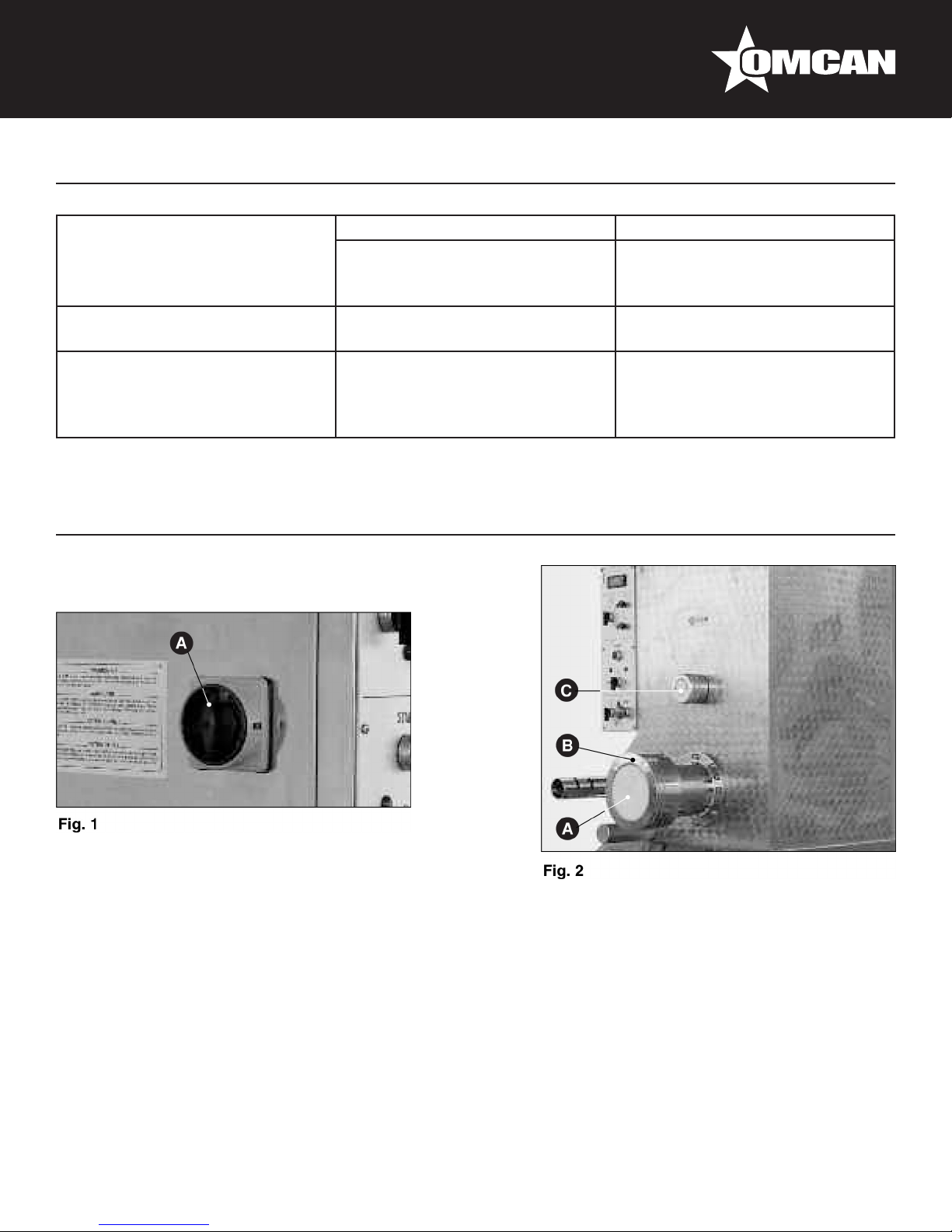
• Position the main switch on “0” (Fig.1 A) and check the correct set-up of the Archimedean screw, making
sure that the cylinder part is sustained by the dragging shaft.
• Then make sure that the plastic cap (Fig.2 A) which replaces the drawplate is correctly positioned and the
ring nut (Fig.2 B) is well-screwed on.
• Finally block the mixer in its place, thanks to the head-knob (Fig.2 C).
Lift the pool cover or hopper (Fig.3 B), by pulling the hooking lever (Fig.3 A), and always put in the pre-
established ingredients in the following sequence: our and then, after closing the cap, all the other liquid
elements. In order to obtain the right dough, you need to create the precise ratio between the weight of the
our and the weight of the liquid part; in order to obtain a very good product, the our has to contain a humidity
percentage of no more than 15%; this allows the addition of water equal to 33% or up to
35% of the our’s weight.
If you are using ours with different humidity contents, please change the quantity of the liquid in the opposite
8
Page 9

Operation
ratio. Moreover, in order to better use the machine, the product inside the pool has to be higher than at a
minimum level which coincides more or less with the position of the mixer axle.
USEFUL ADVICE IN ORDER TO OBTAIN A GOOD DOUGH
Any kind of our can be used (bran or bran our). The dough can be kneaded only with eggs or with a mix
of water and eggs. Water can be partially replaced by spinach or well cut vegetables in order to obtain green
noodles. Because the our’s humidity changes according to the kind used, the environment and the place
where it is stocked, the quantities indicated have to be adapted to the kind of our which is used, lowering or
increasing the quantity of water. The dough is the right one when, at the end of kneading process, it is as big
as coffee beans. If the lumps form in the our you have poured in too much liquid. In this case, before turning
the switch FROM KNEADING (Fig.4 A) TO DRAWING (Fig.4 B) you will have to add some more our and
knead a little longer. If the our does not form a ball and is too oury, add some more water. For the dough for
the sheet of pasta which is to be re-kneaded, use “00” our and add two eggs per kilo of our (maximum). With
these quantities you will obtain a very stretchy dough which is easy to knead.
QUANTITIES IN ORDER TO OBTAIN A GOOD DOUGH
• Supposed weight of an egg: 50 grams.
• If you take 1 egg away you need to add 50 grams of water.
• To obtain a good dough: 1 kg of our + 350 grams of humidity-liquid.
Close the cover or the hopper, position the general switch to “1” (Fig.5 A) and put the selector on position
(Fig.6 A). Push the start button (Fig.6 B). Add the liquid part pouring it gradually but as quickly as possible
through the small hole in the cover. At the end of the kneading operation, which should take around 10
minutes, make sure the product has the right thickness and should look like coffee beans (check through the
small holes of the cover). Turn the machine off by switching the selector to “0” (Fig.6 A).
INSTALLATION OF THE DRAWPLATE AND START-UP OF PRODUCTION
Make sure the machine is switched off.
Withdraw the drawplate and the lter requested from the container lled with water where it was put after
its last use. Thoroughly rinse with plenty of running, warm water, in order to have the piece at the right
temperature (see CLEANING). Dry it with a soft cloth. Unscrew the blocking ring nuts (Fig.7 A) and carefully
clean the internal part including the edging. Take the plastic cap off (Fig.7 B). Set up the lter and the hopper
while taking good care of the Archimedean screw frame at the center of the lter disk and drawplate (Fig.9 A
and B). Close the metal ring with the help of the wrench supplied (Fig.8 A) and check that all the pieces are in
the right places and not axially moved (see correct setting up procedure of the Archimedean screw). In order
to start production, position the selector on the position (Fig.6 A) and push the start button (Fig.6 B). The
initial product coming out of the machine has an unacceptable appearance; this is the reason why it has to be
eliminated. After a short time (a couple of minutes) the product coming out is acceptable, the colour goes from
whitish to yellow and it has a greater consistency.
In order to cut the pasta to the desired length it is necessary to set up the cutting device, made up of motor and
knife, chosen from those available.
9
Page 10

Operation
CUTTING GROUP
The cutting group is chosen on the basis of the length of the pasta to be cut.
LONG-TYPE PASTA
Use group 1 with knife with alternative movement. Release the xed handwheel (Fig.10 A) and wheel the
group (Fig.10 B) until reaching the edge of the guide slit, the knife (Fig.10 C) must be at about the same height
as the drawplate axle). Block the handwheel in the new position.
NOTE: Make sure that group 2 (Fig.10 D) which controls the rotating knife is in the stop position.
WARNING: The group position is signalled by a safety microswitch which prevents the functioning of
the knife, if the group is not inserted in its correct functioning position.
Position the selector (Fig.11 A) on position 1 and regulate the potentiometer (Fig.11 B) to the number desired,
bearing in mind that the numbers indicate the interval shown in seconds x 2, which pass between one cut and
another.
SHORT-TYPE PASTA
Use group 2 (Fig.12 A) with rotating knife. Make sure that the control group 1 (Fig.12 B) is not in the functioning
position, in order to avoid interference between the two groups. Prepare the group, by simply mounting the
knife (Fig.12 C) on the control shaft (the knife must not be blocked in the shaft) while it is in the stop position.
Position the cutting group (Fig.12 A) after having released the handwheel (Fig.13 A) in front of the drawplate
(Fig.12 D), paying attention that the knife (Fig.12 C) moves axially towards the motor and adheres well to the
drawplate (Fig.12 D). To complete this operation, facilitate the movement of the knife by helping yourself, with
your hands, closing the knife tang between two ngers (Fig.12).
NOTE: This group is also controlled by a micro-switch that does not allow the knife to function in a
different position from the one illustrated above.
NOTE: Remember to position the cutting group protection correctly.
Block the handwheel (Fig.13 A) and the selector on position 2 (Fig.11 A) and regulate the knife speed
according to the desired pasta length, by turning the speed-control knob (Fig.11 D). The speed increases
steadily from 0 to maximum, the numbers go from 0 to 10. If the product is quite wet and tends to be sticky, it is
best to dry the surface in any case, by switching on the fan (Fig.14 A).
COOLING SYSTEM OF THE EXTRUSION SLEEVE
The machine is equipped with a cooling device of the extrusion sleeve that can be on, while bearing in mind
some functioning parameters: Mixture consistency and room temperature. Open the regulating tap before
beginning this operation.
NOTE: If the product is kneaded at an excessive temperature, it tends to change colour and/or blanch
slightly.
10
Page 11

Operation
The system functions automatically and maintains the same temperature shown on the extrusion sleeve.
FUNCTIONING OF THE DISPLAY CONTROL (FIG.15 C) AND TEMPERATURE SETTING
When the machine is turned on, the display button ashes for a few seconds and, therefore, shows the
momentary temperature on the extrusion sleeve. To see the last temperature selected, press button “SET”
(Fig.15 A) once. If you want to vary the sleeve control temperature, press the button “SET” and at the
same time button “UP” or “DOWN” (Fig.15 B) depending on whether you want to increase or decrease the
controlled temperature, until you see the desired temperature appear on the display unit. Release the pressed
button, the system memorizes the new temperature, even if the machine is turned off. After a few seconds,
the temperature shown on the sleeve will appear on the display unit. The feeler, positioned on the inside of
the extrusion sleeve shows the temperature taken continuously and while comparing its value with the one
dened, controls the opening and closing of the electrovalve which checks the water for cooling.
At the end of this operation:
• Stop the machine by positioning the pushbutton to start KNEADING/DRAWING and the other control
buttons on the “0” position.
• Rotate the cutting group to the stop position (Fig.8).
• Put the selector on the mixture position for 10-15 seconds in order to eliminate the pressure on the
drawplate caused by the product.
• Return the switch to “0”.
• Turn off the machine pressing the general switch (Fig.1 A).
• Disassemble and wash the movable parts and clean the machine (see CLEANING).
• Turn off the water tap.
Maintenance
CLEANING
Warning: For healthy and hygienic processing of food products, be sure to keep your machine and the
surrounding environment clean.
DANGER: Always cut off the power supply before cleaning.
You have to properly clean all the elements which are in contact with the product (Fig.29) protection cover,
pool , mixer, Archimedean screw, drawplate, lter, ring nut and knife, when the product is still soft.
The moving parts have to be disassembled as follows:
• Mixer: make sure the external shovel is in the upper vertical position (Fig.29 A) (only this position allows
the disassembling of the piece). Disassemble the mixer by unscrewing the external movable support until
releasing the mixer; unthread the shaft from its place and at the same time, rotate the external pin towards
the top. If you want to assemble the piece follow these instructions vice versa. Line the central point of the
shaft with the peg of the moving support (Fig.34 A); thereafter, screw the support, but without blocking it.
11
Page 12

Maintenance
• Metal ring, drawplate and lter: unscrew the metal ring with the appropriate wrench (Fig.30 A) being careful
not to let any pieces fall, since the metal ring is moved from its place, the product and parts still weigh a few
kilos and can easily slip from your hands, causing damage both to people or to the pieces themselves.
• Archimedean screw: after disassembling the ring nut, the drawplate and the lter, the Archimedean screw
can easily be taken off the machine by pushing its spiral from the internal end.
COVER AND POOL CLEANING
Eliminate the dough residue and be sure to thoroughly clean the most remote-access pieces: connections of
the Archimedean screw (Fig.31 B) and mixer (Fig.31 A) movements, extrusion sleeve, pool internal parts and
cover grid. Use some warm water in order to eliminate the residual product and then rinse; dry the surfaces
with the help of blotting paper and disinfectant, with a soft cloth dipped in odourless disinfectant.
WARNING: Never use non-nutritional, abrasive or corrosive chemicals to clean. Also never use coarse
or abrasive objects such as steel wool, abrasive sponges and so on.
To clean the internal and external parts of the machine:
• Remove power supply plug from power mains socket.
• Clean coated surfaces with soft cloth and disinfect with alcohol.
• For the inside parts of the machine, take off the bigger back panel (Fig.33 A) and carry out the cleaning
of the machine, bearing in mind the grease and dust, that are sometimes present; when nished, replace
panel.
CLEANING OF MIXER, ARCHIMEDEAN SCREW, METAL RING, FILTER, DRAWPLATE
AND KNIVES
WARNING: The alternative knife must not be taken apart: remove product left overs with a soft brush.
Eliminate the dough residue and wash the pieces with water; you may use a soft brush or a plastic pallet knife.
These elements can be thoroughly washed in a dishwasher. Rinse and dry the mixer, the Archimedean screw,
the metal ring and the knife and reassemble them on the machine. The drawplate and lter must be kept in a
container placed in water for the entire period in which they are not being used. For reasons of hygiene, please
change the water every day.
WARNING: Clean the surface below the machine daily, if necessary, temporarily move the machine
from its usual working position.
MAINTENANCE AND ADJUSTMENT
WARNING: Remember that all maintenance operations are dangerous if you do not rst disconnect the
power supply plug from the power mains.
The machine parts requiring maintenance are the following: the Archimedean screw reducer, the upright push-
bearing support, the movable mixer support, the sliding chains and belts. Disassemble the bigger back panel
(Fig.33 A) upright.
12
Page 13

Maintenance
MIXER SUPPORT (FIG.34)
Use registered fats for foods (USDA-H1) (in case of requirement contact your local dealer); perform
maintenance daily.
PUSH-BEARING SUPPORT (FIG.35 A) AND CHAIN (FIG.36 A)
Use mineral grease type SAE MR3; maintenance needs to be carried out every six months. When controlling,
grease the chains with as much oil as required.
REDUCER FOR EXTRUSION SHAFT (FIG.37)
Change oil after the rst 500 - 1000 functioning hours, letting the carter oil drain out completely from the cap
(Fig.37 A), afterwards, change the oil every 2000 working hours. To check level, see transparent cap positioned
on the left-hand side of the pan (Fig.37 B). Pour the oil through the oil ller cap (Fig.37 C).
BELT STRETCHING
When performing the above mentioned maintenance or when the machine is not working properly, (loss of
rounds) check the correct stretching of the transmission belt (Fig.36 B). For this reason, disassemble the
left-hand side panel (Fig.36 C) from the machine and make sure that the belt is tight enough. If necessary,
use the regulating system, by moving the motor and therefore, putting tension on the belt, without of course
exaggerating. When nished, reset the panel.
Never use the machine with any missing, disassembled or open guards and shields.
If servicing operations require repairs to the electrical system and/or replacement of bearings or
mechanical components, call an expert technician or your local dealer.
Troubleshooting
Problem Cause Solution
Machine operation Failure Disconnected plug. Connect plug.
Plug leads not correctly connected. Check lead connections.
The product gets stuck when being
poured out.
Trip switch adjusted for insufcient
values.
Unsuitable trip switch. Replace trip switch.
Fuses burnt out. Replace fuse.
Safety rod on pool cover not
properly inserted
Too humid dough is used. Reduce the quantity of water
Adjust trip switch accordingly.
Position rod at end of stroke.
used for the dough respecting the
abovementioned percentage.
13
Page 14
Troubleshooting
The product looks unacceptable
even after the initial minutes: it
breaks and loses our.
The product does not come out of
the drawplate.
The product crushed at an edge
during cutting.
Too short kneading time. Increase the kneading time.
Not enough water percentage. Increase the quantity of
The blocking of the drawplate
because of dried dough.
Cutting speed not adequate (too
low).
Figure Drawings
water in order to respect the
aforementioned percentage.
Disassemble and clean the
drawplate.
Increase cutting speed: remember
that the length of the pasta
cut, depends on the pasta and
drawplate diameter.
14
Page 15

Figure Drawings
15
Page 16
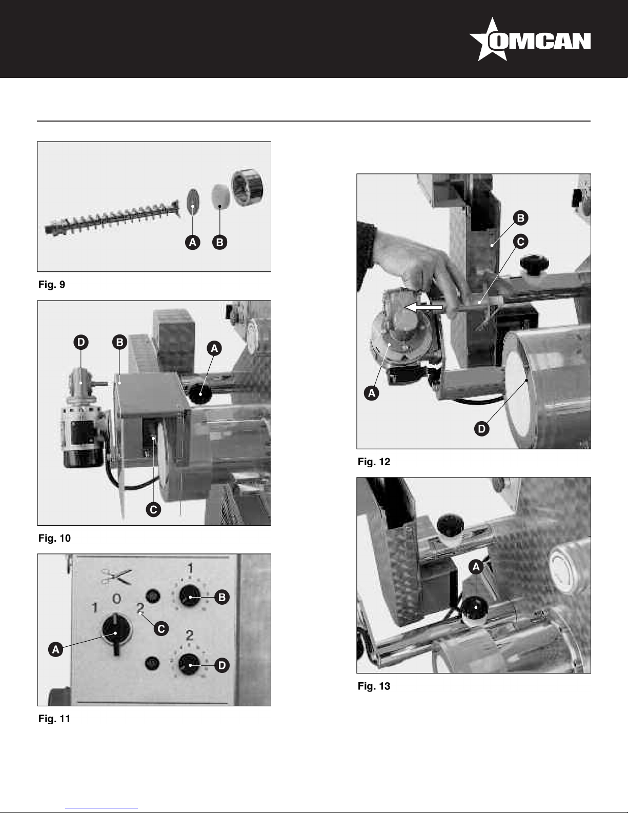
Figure Drawings
16
Page 17
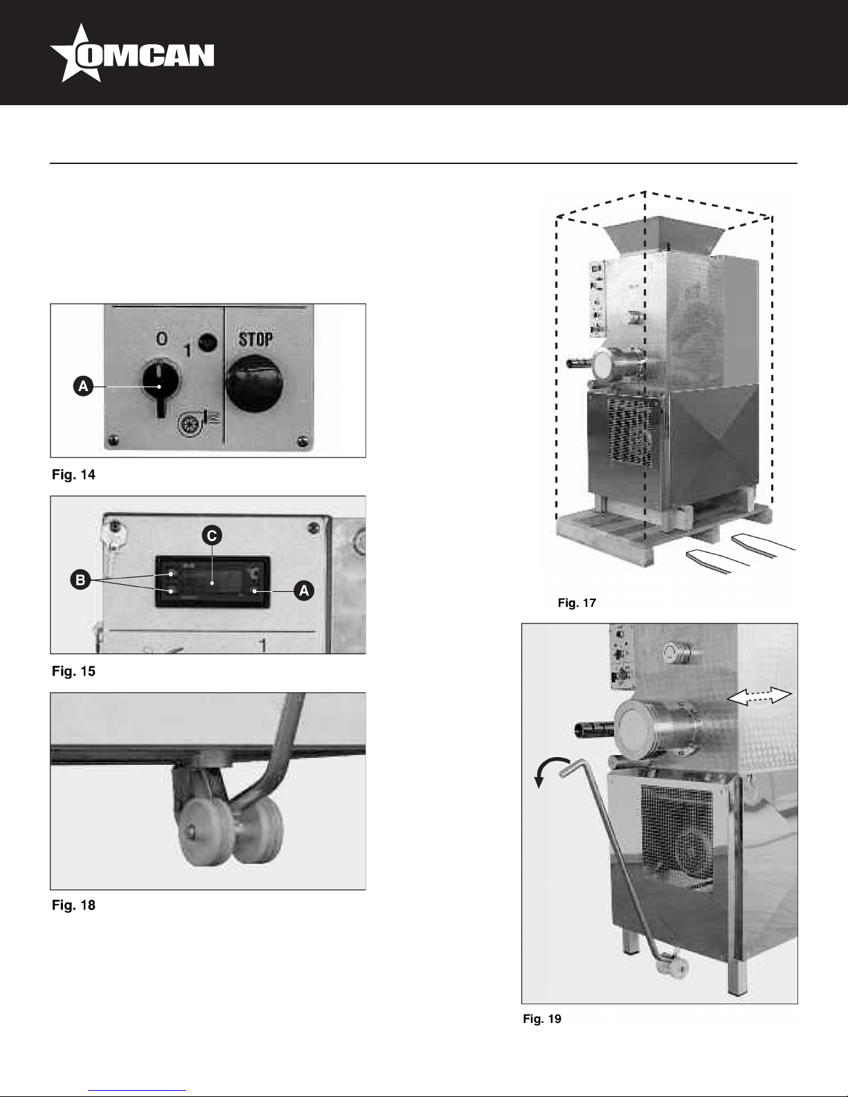
Figure Drawings
17
Page 18
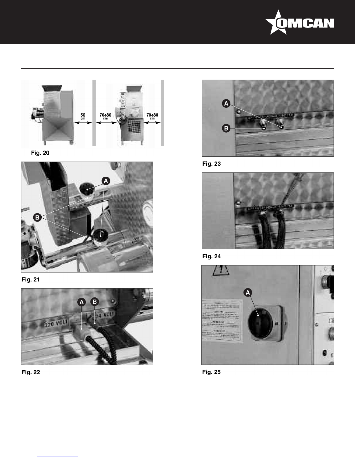
Figure Drawings
18
Page 19
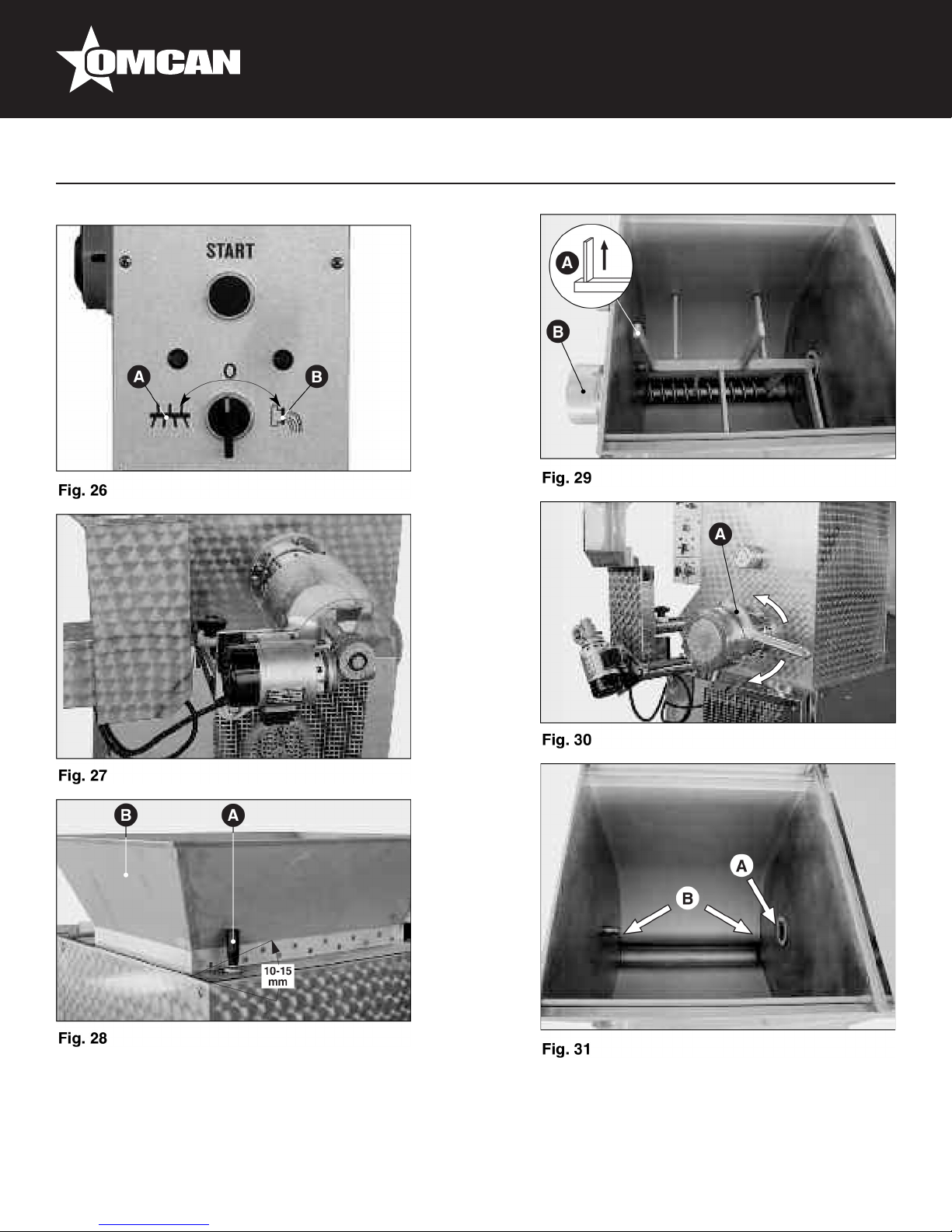
Figure Drawings
19
Page 20
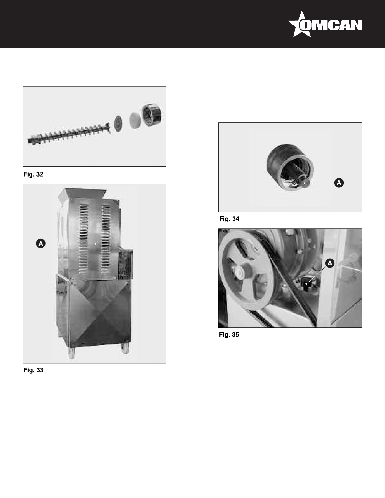
Figure Drawings
20
Page 21

Figure Drawings
21
Page 22

Parts Breakdown
Model PM-IT-0080 13286
22
Page 23
Model PM-IT-0080 13286
Parts Breakdown
23
Page 24
Parts Breakdown
Model PM-IT-0080 13286
24
Page 25

Parts Breakdown
Model PM-IT-0080 13286
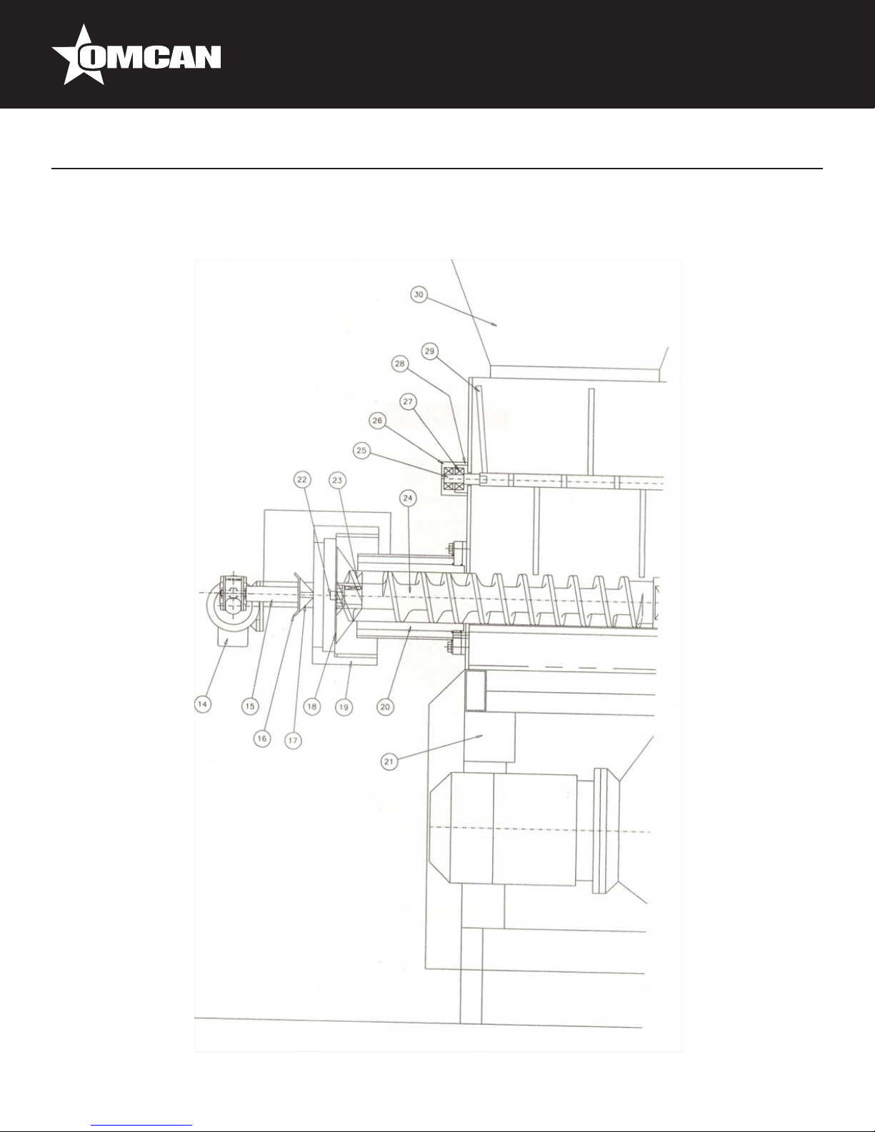
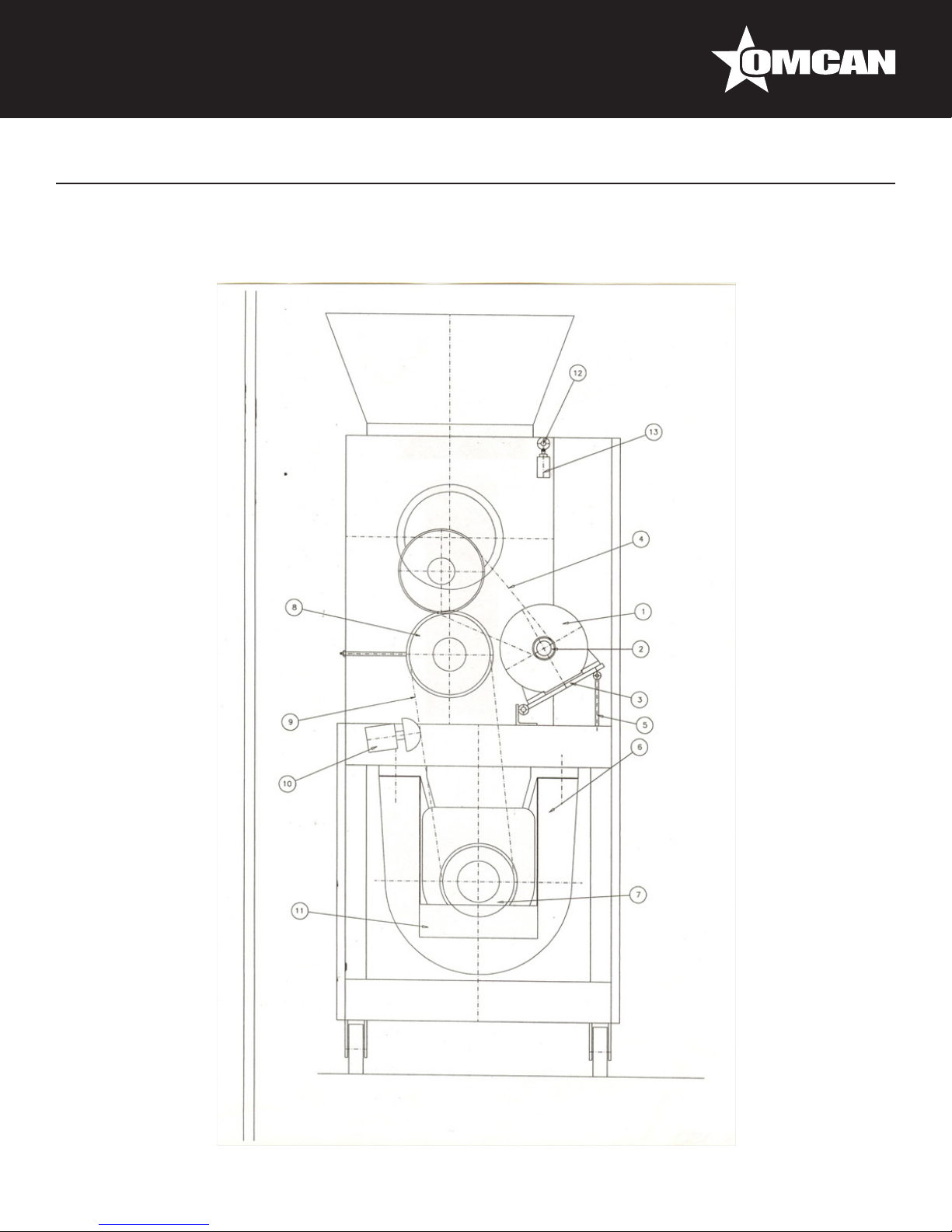
Item No. Description Position Item No. Description Position Item No. Description Position
62520 Mixer Motor for TR150 1 62538 Ring for TR150 19 62556 Distance for TR150 37
62521 Motor Pulley for TR150 2 62539 Cylinder for TR150 20 62557 Bearing for TR150 38
62522 Motor Support for TR150 3 62540 Fan for TR150 21 62558 Red Cover for TR150 39
62523 Belt for TR150 4 62541 Central Steering Wheel for TR150 22 62559 Pin for TR150 40
62524 Tightener for TR150 5 62542 Front Mixer for TR150 23 62560 Lower Support for TR150 41
62525 Motor Screw for TR150 6 62543 Compression Screw for TR150 24 62561 Sealing Ring for TR150 42
62526 Pinion for TR150 7 62544 Mobile Tree Mixer for TR150 25 62562 Distance for TR150 43
62527 Pinion Duct for TR150 8 62545 Mobile Mixer Support for TR150 26 62563 Distance for TR150 44
62528 Chain for TR150 9 62546 Bearing for TR150 27 62564 Wheel for TR150 45
62529 Idler Chain for TR150 10 62547 Fixed Mixer Support for TR150 28 62565 Fixed Motor Knife for TR150 46
62530 Oil Tank for TR150 11 62548 Mixer for TR150 29 62566 Mobile Support for TR150 47
62531 Cam for TR150 12 62549 Hopper for TR150 30 62567 Base Motor Knife for TR150 48
62532 Micro Switch for TR150 13 62550 Superior Support for TR150 31 62568 Knife Protection for TR150 49
62533 Cutting Motor for TR150 14 62551 Tree for TR150 32 62569 Electrical Frame for TR150 50
62534 Tri-Blade for TR150 15 62552 Bearing for TR150 33 62570 Filter for TR150 51
62535 Light Support for TR150 16 62553 Mixer Reducer for TR150 34 62571 Electric Valve for TR150 52
62536 Long for TR150 17 62554 Conducted Pulley for TR150 35
62537 Filter for TR150 18 62555 Lower Tree for TR150 36
25
Page 26
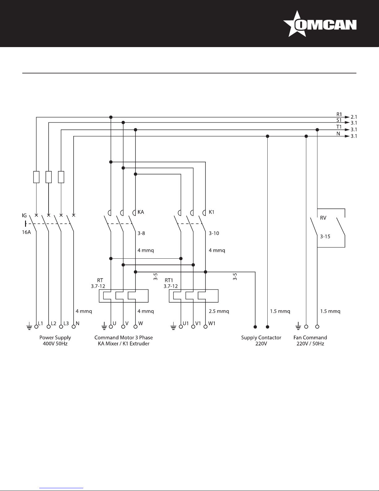
Electrical Schematics
Model PM-IT-0080 13286
26
Page 27
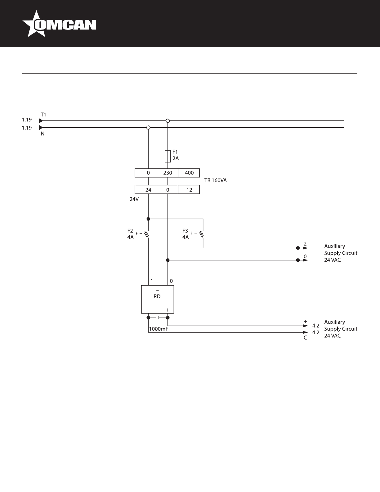
Model PM-IT-0080 13286
Electrical Schematics
27
Page 28
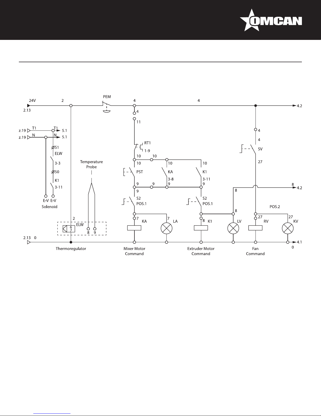
Electrical Schematics
Model PM-IT-0080 13286
28
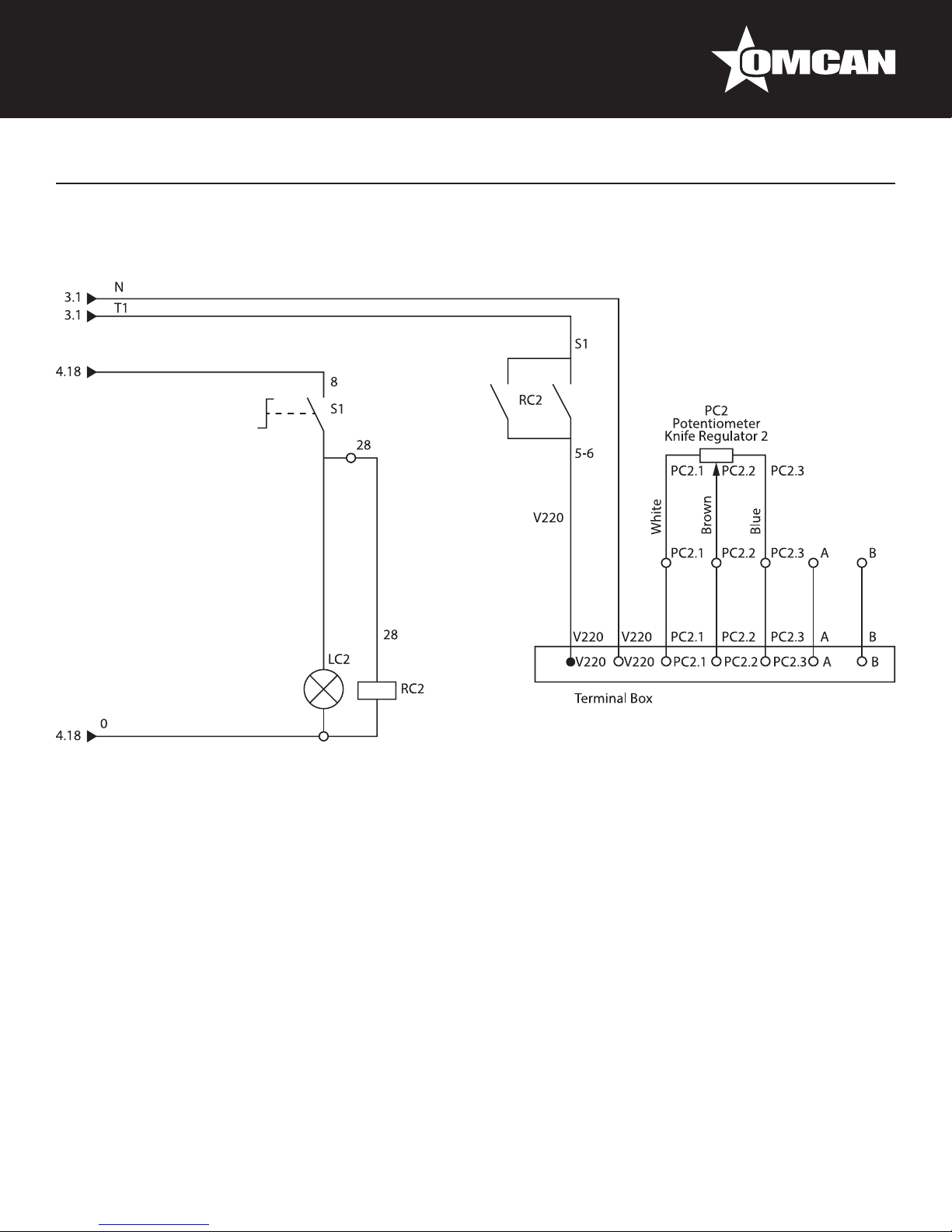
Page 29

Model PM-IT-0080 13286
Electrical Schematics
29
Page 30
Electrical Schematics
Model PM-IT-0080 13286
30
Page 31

Warranty Registration
Thank you for purchasing an Omcan product. To register your warranty for this product, complete the information below, tear off the card at
the perforation and then send to the address specied below. You can also register online by visiting:
Merci d’avoir acheté un produit Omcan. Pour enregistrer votre garantie pour ce produit, complétez les informations ci-dessous, détachez la
carte au niveau de la perforation, puis l’envoyer à l’adresse spécié ci-dessous. Vous pouvez également vous inscrire en ligne en visitant:
Gracias por comprar un producto Omcan usted. Para registrar su garantía para este producto, complete la información a continuación,
cortar la tarjeta en la perforación y luego enviarlo a la dirección indicada a continuación. También puede registrarse en línea en:
www.omcan.com/warrantyregistration.html
For mailing in Canada
Pour postale au Canada
Por correo en Canadá
OMCAN
PRODUCT WARRANTY REGISTRATION
3115 Pepper Mill Court,
Mississauga, Ontario
Canada, L5L 4X5
PRODUCT WARRANTY REGISTRATION
4450 Witmer Industrial Estates, Unit 4,
For mailing in the US
Pour diffusion aux États-Unis
Por correo en los EE.UU.
OMCAN
Niagara Falls, New York
USA, 14305
or email to: service@omcan.com
Purchaser’s Information
Name: Company Name:
Address:
Telephone:
City: Province or State: Postal or Zip: Email Address:
Country: Type of Company:
Restaurant Bakery Deli
Dealer from which Purchased: Butcher Supermarket Caterer
Dealer City: Dealer Province or State: Institution (specify):
Invoice: Other (specify):
Model Name: Model Number: Serial Number:
Machine Description:
Date of Purchase (MM/DD/YYYY): Date of Installation (MM/DD/YYYY):
Would you like to extend the warranty? Yes No
Thank you for choosing Omcan | Merci d’avoir choisi Omcan | Gracias por elegir Omcan
31
Page 32

Since 1951 Omcan has grown to become a leading distributor of equipment and supplies to the North
American food service industry. Our success over these many years can be attributed to our commitment
to strengthen and develop new and existing relationships with our valued customers and manufacturers.
Today with partners in North America, Europe, Asia and South America, we continually work to improve
and grow the company. We strive to offer customers exceptional value through our qualied local sales
and service representatives who provide convenient access to over 3,500 globally sourced products.
Depuis 1951 Omcan a grandi pour devenir un des “leaders” de la distribution des équipements et
matériel pour l’industrie des services alimentaires en Amérique du Nord. Notre succès au cours de ces
nombreuses années peut être attribué à notre engagement à renforcer et à développer de nouvelles
et existantes relations avec nos clients et les fabricants de valeur. Aujourd’hui avec des partenaires en
Amérique du Nord, Europe, Asie et Amérique du Sud, nous travaillons continuellement à améliorer et
développer l’entreprise. Nous nous efforçons d’offrir à nos clients une valeur exceptionnelle grâce à
nos ventes locales qualiées et des représentants de service qui offrent un accès facile à plus de 3500
produits provenant du monde entier.
Desde 1951 Omcan ha crecido hasta convertirse en un líder en la distribución de equipos y suministros
de alimentos en América del Norte industria de servicios. Nuestro éxito en estos años se puede atribuir
a nuestro compromiso de fortalecer y desarrollar nuevas relaciones existentes con nuestros valiosos
clientes y fabricantes. Hoy con socios de América del Norte, Europa, Asia y América del Sur, que trabajan
continuamente para mejorar y crecer la empresa. Nos esforzamos por ofrecer a nuestros clientes valor
excepcional a través de nuestro local de ventas y representantes de los servicios que proporcionan un
fácil acceso a más de 3,500 productos con origen a nivel mundial.
 Loading...