

Page 1
Installaon, Operaon and Maintenance VL10/…‐en Rev.08/2018
INSTALLATION, OPERATION AND
MAINTENANCE MANUAL
ENGLISH
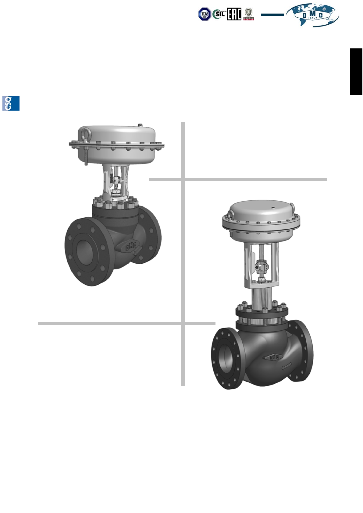
Globe Valves
SERIES
VD10 - KD10 - KA10
KD20 - KA20
Our products are manufactured under ISO-9001 Quality Assurance System, approved by CSQ certified under no.9190.OMC2 - FIRST ISSUE 1994/08/04
OMC S.p.A: Via G. Galilei, 18 - 20060 - Cassina de Pecchi (MI) - ITALY - www.omcvalves.com - Tel.: (+39) 02.95.28.468
Page 1
Page 2

Installaon, Operaon and Maintenance Manual VL10/…‐en Rev.08/2018
TABLE OF CONTENTS
1.0 SAFETY INFORMATION
1.01 INTENDED USE
ENGLISH
1.02 ACCESS
1.03 LIGHTING
1.04 HAZARDOUS FLUIDS IN THE PIPE
1.05 ENVIRONMENTAL SITUATIONS
1.06 TEMPERATURE
1.07 SYSTEM
1.08 PRESSURIZED SYSTEMS
1.09 TOOLS AND CONSUMABLE PARTS
1.10 PROTECTION CLOTHES
1.11 QUALIFICATION OF OPERATORS IN CHARGE OF THE WORKS
1.12 HANDLING
1.13 FREEZING
1.14 OTHER RISKS
1.15 DISPOSAL
1.16 RISK OF CORROSION AND/OR EROSION
2.0 INSTALLATION
2.01 ASSEMBLY OF THE VALVE ON THE PIPE
3.0 ACTUATOR CONNECTION
3.01 PNEUMATIC ACTUATOR CONNECTION
3.02 ELECTRIC ACTUATOR CONNECTION
4.0 MAINTENANCE
4.01 VALVE/ACTUATOR SEPARATION
4.02 REPLACEMENT OF THE PLUG SEAT OF THE STANDARD VALVE
4.03 REPLACEMENT OF THE PLUG SEAT WITH QUICK CHANGE SEAT
4.04 REPLACEMENT OF THE PLUG SEAT OF THE BALANCED VALVE
4.05 REPLACEMENT OF THE PLUG SEAT OF THE VALVE WITH BELLOWS
4.06 REPLACEMENT OF THE STEM PACKING GLAND
5.0 TIGHTENING TORQUES
6.0 SIZES OF PLUG CONNECTION
7.0 PERIODICAL OPERATIONS
8.0 AVAILABLE SPARE PARTS
9.0 PRESSURE/TEMPERATURE REPORT OMC-TUV-00 Rev.03/2018
10.0 REFERENCES OF THE EUROPEAN DIRECTIVE FOR PRESSURE EQUIPMENT
2014/68/EU
11.0 PLATES
11.01 IDENTIFICATION PLATES
11.02 “EC” PLATE PURSUANT TO DIRECTIVE 2014/68/EU
Page 2
OMC S.p.A: Via G. Galilei, 18 - 20060 - Cassina de Pecchi (MI) - ITALY - www.omcvalves.com - Tel.: (+39) 02.95.28.468
Our products are manufactured under ISO-9001 Quality Assurance System, approved by CSQ certified under no.9190.OMC2 - FIRST ISSUE 1994/08/04
Page 3

Installaon, Operaon and Maintenance VL10/…‐en Rev.08/2018
1.0 SAFETY INFORMATION
The safe operation of this product is ensured only if it is installed, commissioned, used and maintained in an
appropriate way by qualified personnel in compliance with the operating instructions.
1.01 INTENDED USE
Verify that the valve is suitable for the intended use and application by checking:
- that the material of which the valve is made up of is compatible with the process fluid;
- that the valve is suitable for the pressures and temperatures of the process fluid;
- that a suitable safety device is fitted to the system to prevent any hazardous overpressures or overtemperatures
in the system.
OMC valves are not intended to withstand any external stresses which can be induced by the systems in which
they are inserted. The installer must take account of these stresses and take the appropriate measures to prevent
them.
1.02 ACCESS
Ensure safe access and, if required, a safe working platform (with a suitable protection) is provided, before
operating or installing the product. Arrange the suitable lifting means, if required.
1.03 LIGHTING
Ensure the area around the valve is adequately lit and is suitable to safely work on the valve.
1.04 HAZARDOUS FLUIDS IN THE PIPE
Take account of the content of the pipe (process fluid) or anything it may have previously contained. Take special
safety precautions where flammable, hazardous substances are present, or where fluid pressure or temperature
may be hazardous to health.
ENGLISH
1.05 ENVIRONMENTAL SITUATIONS
Take account of: areas at risk of explosion, lack of oxygen (such as tanks, wells, etc.…), hazardous gases,
temperature limits, high or low temperature surfaces, risk of fire (for example during welding operations),
excessive noise, moving machines.
1.06 TEMPERATURE
Wait until the temperature normalizes after the interception to prevent any risks of burn or freezing.
1.07 SYSTEM
Take account of the possible effects on the whole expected working system.
In particular, you must assess any proposed actions and the consequences that may result in any other
part of the system, You must ensure the system remains safe at all times.
Make sure that the control valve is isolated via shut-off valves to prevent any abrupt variations to the system.
1.08 PRESSURIZED SYSTEMS
Make sure that the pressure is isolated and discharged to the atmospheric pressure in safe conditions. Take
account of a double insulation (double block and vent) and the blocking or the labelling of the closed valves. Do
not consider the system depressurized even if the pressure gauge indicates zero pressure. The depressurization
process should include taking the valve through its full stroke, to ensure all pressure is allowed to exhaust to
atmosphere.
During the operation the valve is pressurized. Before performing any maintenance operation or action on
the flanges and closing caps, make sure that the line is depressurized (0 bar) and at ambient temperature.
Our products are manufactured under ISO-9001 Quality Assurance System, approved by CSQ certified under no.9190.OMC2 - FIRST ISSUE 1994/08/04
OMC S.p.A: Via G. Galilei, 18 - 20060 - Cassina de Pecchi (MI) - ITALY - www.omcvalves.com - Tel.: (+39) 02.95.28.468
Page 3
Page 4
Installaon, Operaon and Maintenance Manual VL10/…‐en Rev.08/2018
1.09 TOOLS AND CONSUMABLE PARTS
Before starting the work, make sure to have at your disposal all the tools required to perform it, do not make use
of inappropriate tools. Use only OMC original spare parts.
ENGLISH
1.10 PROTECTION CLOTHES
Take account of whether you and/or others need some clothes against the hazards, such as chemical products,
temperatures, radiations, noise, fall of objects, risks for eyes and face.
1.11 QUALIFICATION OF THE OPERATORS IN CHARGE OF THE WORKS
All works must be performed and supervised by some skilled, trained and competent personnel.
1.12 HANDLING
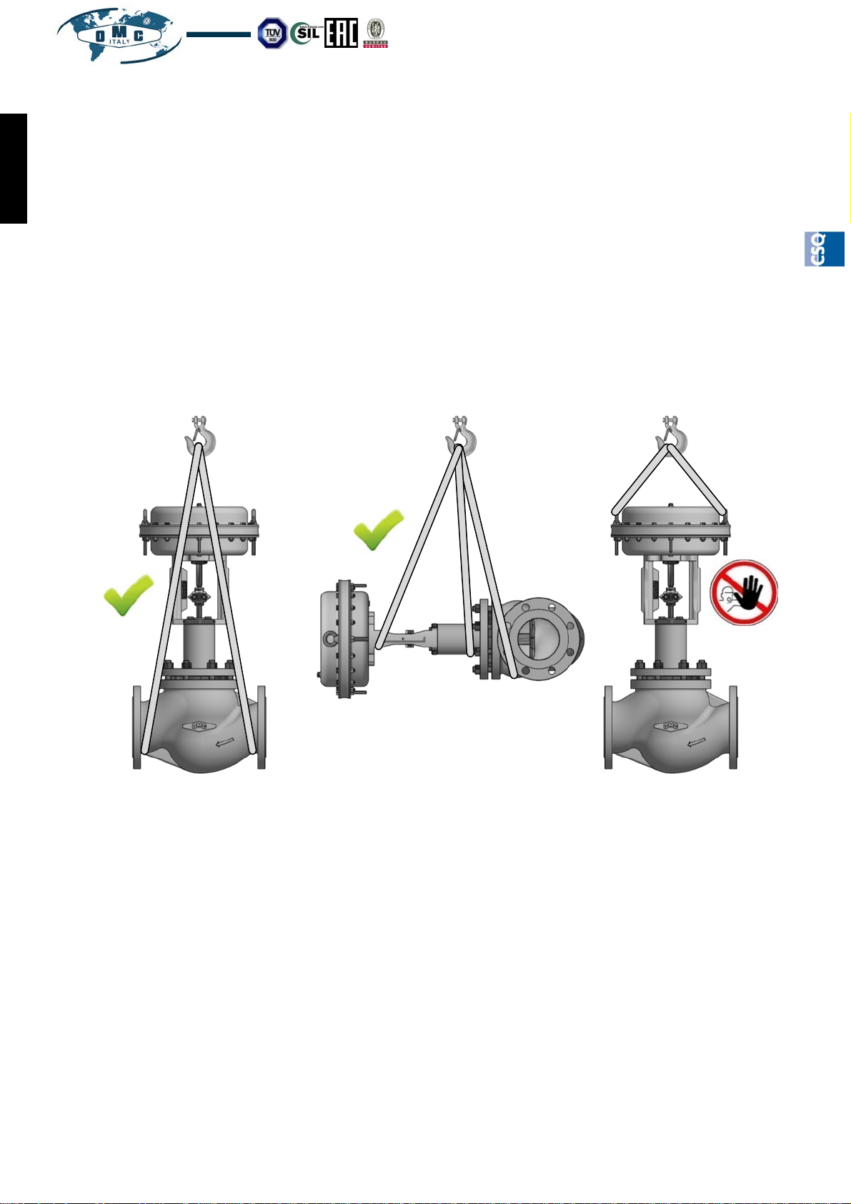
Use suitable lifting means for the handling of the products by assessing all the risks concerning the lifting, the
environment load, the individual and the circumstances of the work which is about to be performed.
CORRECT
CORRECT WRONG
1.13 FREEZING
Protect the product in freezing environments where temperatures are lower than the freezing point of the process
fluid.
1.14 OTHER RISKS
During the operation, the external surface of the product can be at temperatures which are hazardous to touch.
Take account of this risk.
1.15 DISPOSAL
The product should be disposed of in accordance with local legislation. This may be different in each State/
Country/Nation. It is the users responsibility to dispose of the product according to local requirements.
1.16 RISK OF CORROSION AND/OR EROSION
Periodically verify any phenomena of internal and/or external corrosion and/or erosion as they may
significantly damage the pressurized parts by locally reducing the thickness and as a consequence the
safety degree.
Our products are manufactured under ISO-9001 Quality Assurance System, approved by CSQ certified under no.9190.OMC2 - FIRST ISSUE 1994/08/04
Page 4
OMC S.p.A: Via G. Galilei, 18 - 20060 - Cassina de Pecchi (MI) - ITALY - www.omcvalves.com - Tel.: (+39) 02.95.28.468
Page 5
Installaon, Operaon and Maintenance VL10/…‐en Rev.08/2018
2.0 INSTALLATION
All work must be performed and supervised by skilled, trained and competent personnel.
The valve body casting is marked with an arrow showing the direction of flow and its normal flow path. The
casting also has markings which show the type of material and maximum operating pressure.
Before installing the valve, make sure that the inside of the is clean, by performing, if required, an energetic
blowing with steam or compressed air.This should be done with caution.
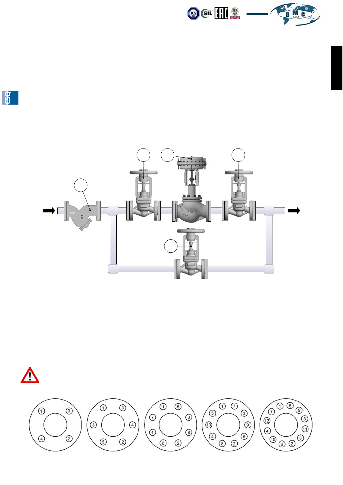
The installation of a filter (pos. A Pic. 1) upstream the valve will prevent dirt entering the valve.
To allow periodical maintenance of valves that are installed on continuously operating systems, it is
recommended to install two Isolating valves, located upstream (pos. B Pic. 1) and downstream (pos. C Pic. 1) of
the control valve, and a by-pass one (pos. D Pic. 1). Use the by-pass valve (pos. D Pic. 1) to manually regulate
the process when the control valve is temporarily disconnected. The two shut-off valves must have the same
internal diameter of the control valve. During the installation of the valve, make sure that the flow in the pipe goes
in the same direction as indicated by the arrow on the valve body.
B C E
Pic. 1 Installation diagram
ENGLISH
A
D
The assembling position of the valve does not limit its operation, but it is recommended to assemble the valve
with the actuator pointed upward (pos. E Pic.1) as other positions may allow the accumulation of any impurities
which are contained in the fluid thus damaging the valve itself.
2.01 FITTING THE VALVE TO THE PIPE
To ensure a uniform load and a uniform alignment, the flange bolts must be gradually tightened in criss-cross
sequence, as indicated in Pic.2
Prevent any excessive tightening. Use the recommended tightening torques. Prevent any pipe
misalignment. Choose the flange gaskets according to the operating conditions.
ATTENTION!!! For valves with braze-on connections, the welding operation must be performed
only by qualified personnel and, in order to prevent any damages to the valves, keep the valve
body cold during the above-mentioned operation.
Our products are manufactured under ISO-9001 Quality Assurance System, approved by CSQ certified under no.9190.OMC2 - FIRST ISSUE 1994/08/04
OMC S.p.A: Via G. Galilei, 18 - 20060 - Cassina de Pecchi (MI) - ITALY - www.omcvalves.com - Tel.: (+39) 02.95.28.468
Pic. 2 Tightening sequence
Page 5
Page 6
Installaon, Operaon and Maintenance Manual VL10/…‐en Rev.08/2018
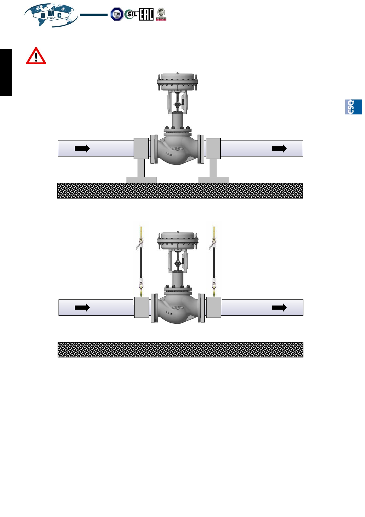
ATTENTION!!! Any excessive weight of the valve might damage the system structure. If required,
support the valve by using suitable devices (Pic.3) and/or ropes (Pic.4)
ENGLISH
Pic. 3 Installation with
supports on the ground
Pic. 4 Installation with
lifting ropes
3.0 ACTUATOR CONNECTION
3.01 PNEUMATIC ACTUATOR CONNECTION
The pneumatic actuator is provided with two 1/4"NPT connections, one of which is closed by a filter. Connect the
control air pipe to the connection which has remained free. The control air must be clean, dry and free from oil
and grease and must not exceed an allowed maximum pressure. The signal required to control the valve is
provided on the plate fixed on the actuator’s yoke. If the valve is provided with a pilot positioner, refer to its
manual.
For the maintenance operations of the OMC pneumatic actuators, refer to the specific manual.
3.02 CONNECTION OF ELECTRIC ACTUATOR
For the connection of the electric actuator refer to its specific manual.
Page 6
OMC S.p.A: Via G. Galilei, 18 - 20060 - Cassina de Pecchi (MI) - ITALY - www.omcvalves.com - Tel.: (+39) 02.95.28.468
Our products are manufactured under ISO-9001 Quality Assurance System, approved by CSQ certified under no.9190.OMC2 - FIRST ISSUE 1994/08/04
Page 7
Installaon, Operaon and Maintenance VL10/…‐en Rev.08/2018
4.0 MAINTENANCE
All operations described below must be performed and supervised by skilled, trained and competent personnel.
The OMC valves are uniquely identified by a serial number fixed on the plate located on the actuator’s yoke. To
order any spare parts or for any other need, always refer to the above-mentioned number.
During operation the valve is pressurized. Before performing any maintenance operation or
action on any pressure retaining part, make sure that the line is depressurized (0 bar) and at
ambient temperature.
4.01 VALVE / ACTUATOR SEPARATION
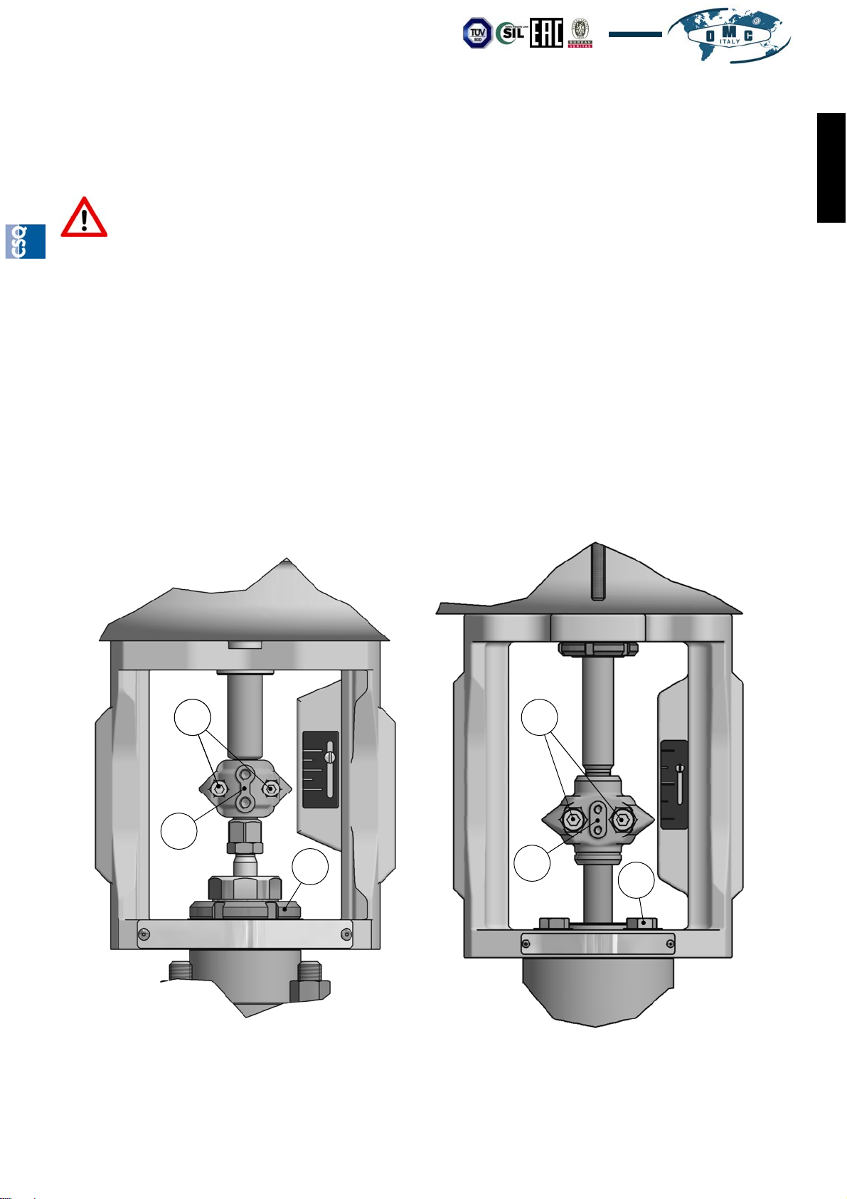
By referring to Pic. 5 (for valves DN15÷DN100 / 1/2”÷4”) or to Pic. 6 (for valves DN125÷DN200 / 6”÷8”) perform
the following steps:
Set the valve to the 50% stroke
Fully unscrew the screws (1) and remove the terminals (2)
For valves DN15 ÷ DN 100 (1/2” ÷ 4”) fully unscrew the ring nut (3).
For valves DN125 ÷ DN 200 (6” ÷ 8”) fully unscrew the screws (4).
Remove the actuator
To re-assemble the valve and actulator the above steps must be performed in the reverse order by paying
attention to the alignment of stem to the value (A)
ENGLISH
1 1
1
2
3
2
4
Pic. 5 Valves DN15 ÷ 100 / 1/2” ÷ 4” Pic. 6 Valves DN125 ÷ 200 / 6” ÷ 8”
Our products are manufactured under ISO-9001 Quality Assurance System, approved by CSQ certified under no.9190.OMC2 - FIRST ISSUE 1994/08/04
OMC S.p.A: Via G. Galilei, 18 - 20060 - Cassina de Pecchi (MI) - ITALY - www.omcvalves.com - Tel.: (+39) 02.95.28.468
Page 7
Page 8
Installaon, Operaon and Maintenance Manual VL10/…‐en Rev.08/2018
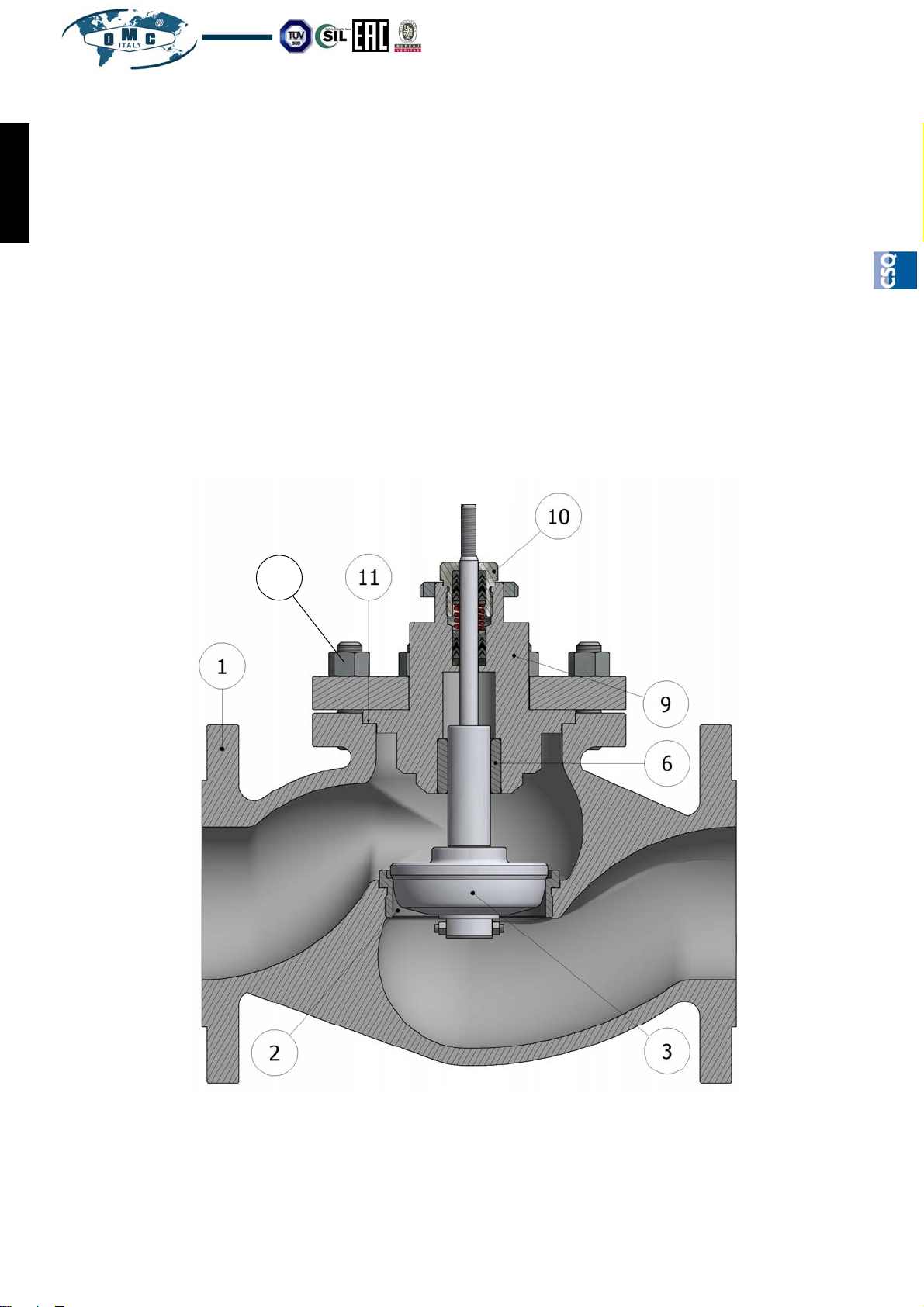
4.02 REPLACEMENT OF THE SEAT/PLUG OF THE STANDARD VALVE
By referring to Pic. 7 perform the following steps:
Separate the actuator from the valve body as described in the previous paragraph
ENGLISH
Loosen the nut (10) and fully unscrew the bolts (15).
Separate the bonnet group (9) from the valve body (1).
Remove the complete plug (3) from the bonnet (9).
If required, unscrew and replace the seat (2) by using the specific wrenches
Insert in the bonnet (9) the new plug by paying attention to grease the stem with some silicone oil.
Always replace the body gasket (11) and carefully clean the supporting surfaces.
Re-assemble everything by repeating the steps in the reverse order and pay specific attention to the re-
alignment of stem, seat and plug.
Gradually tighten the nuts (15) in criss-cross sequence, as indicated in the example in Pic.2 paragraph 2.01
by applying the torques indicated in chapter 5
Attention: when the plug is being replaced it is also nessesary to replace the packing gland (see next
paragraphs).
15
Page 8
Pic. 7 Standard valve
Our products are manufactured under ISO-9001 Quality Assurance System, approved by CSQ certified under no.9190.OMC2 - FIRST ISSUE 1994/08/04
OMC S.p.A: Via G. Galilei, 18 - 20060 - Cassina de Pecchi (MI) - ITALY - www.omcvalves.com - Tel.: (+39) 02.95.28.468
Page 9
Installaon, Operaon and Maintenance VL10/…‐en Rev.08/2018
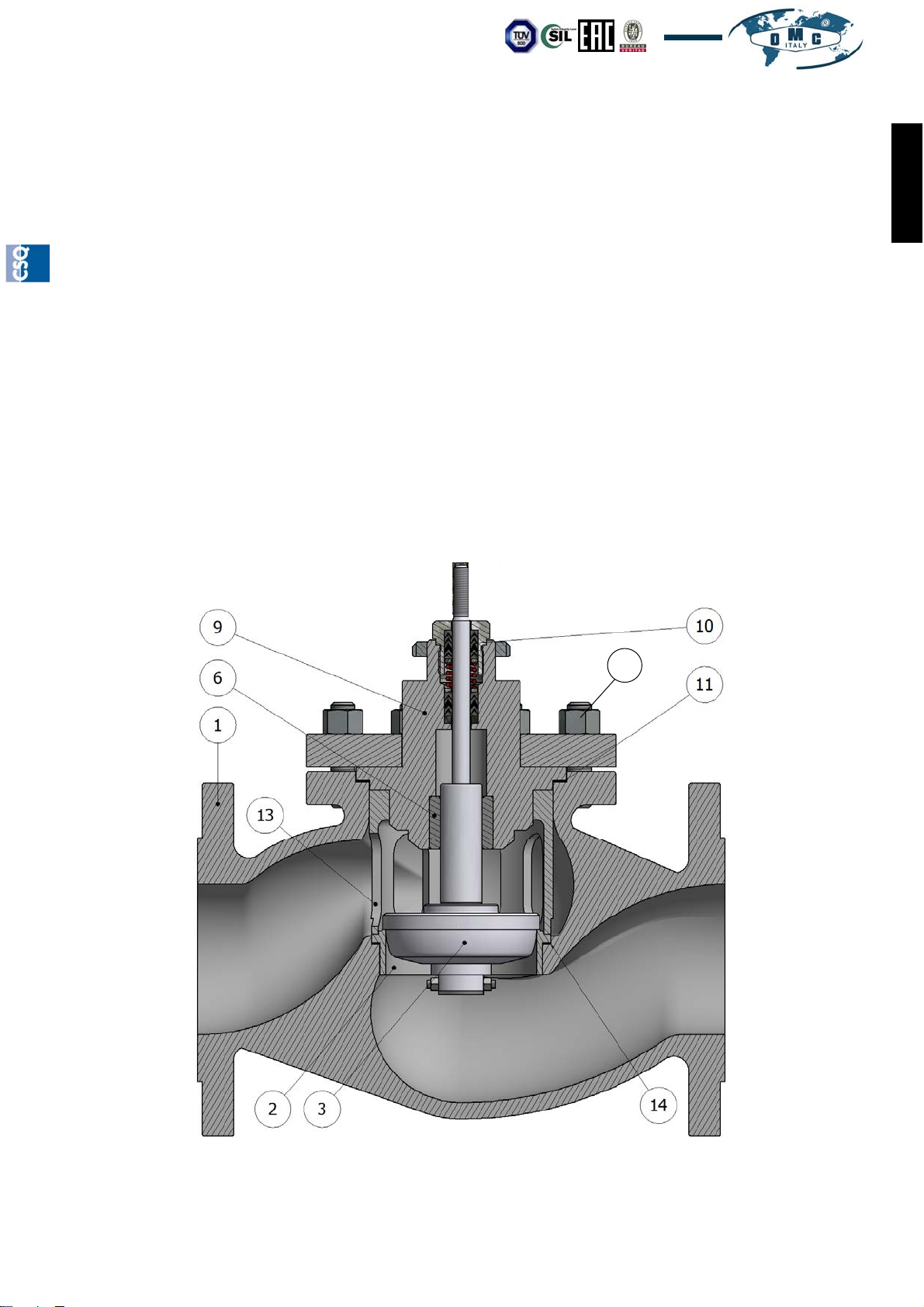
4.03 REPLACEMENT OF THE SEAT/PLUG OF THE VALVE WITH QUICK CHANGE SEAT
By referring to Pic. 8 perform the following steps:
Separate the actuator from the valve body as described in the previous paragraph
Loosen the nut (10) and fully unscrew the bolts (15).
Separate the bonnet group (9) from the valve body (1).
Remove the complete plug (3) from the bonnet (9).
Remove the seat blocking cage (13)
If required, remove and replace the seat (2).
Insert in the bonnet (9) the new plug by paying attention to grease the stem with silicone oil.
Always replace the body gasket (11) and the seat gasket (14) and carefully clean the supporting surfaces.
Re-assemble everything by repeating the steps in the reverse order and pay specific attention to the re-
alignment of stem, seat and plug.
Gradually tighten the nuts (15) in criss-cross sequence, as indicated in the example in Pic.2 paragraph 2.01
by applying the torques indicated in chapter 5
Attention: when the plug is being replaced it is also nessesary to replace the packing gland (see next
paragraphs).
ENGLISH
15
Pic. 8 Valve with Quick Change seat
Our products are manufactured under ISO-9001 Quality Assurance System, approved by CSQ certified under no.9190.OMC2 - FIRST ISSUE 1994/08/04
OMC S.p.A: Via G. Galilei, 18 - 20060 - Cassina de Pecchi (MI) - ITALY - www.omcvalves.com - Tel.: (+39) 02.95.28.468
Page 9
Page 10
Installaon, Operaon and Maintenance Manual VL10/…‐en Rev.08/2018
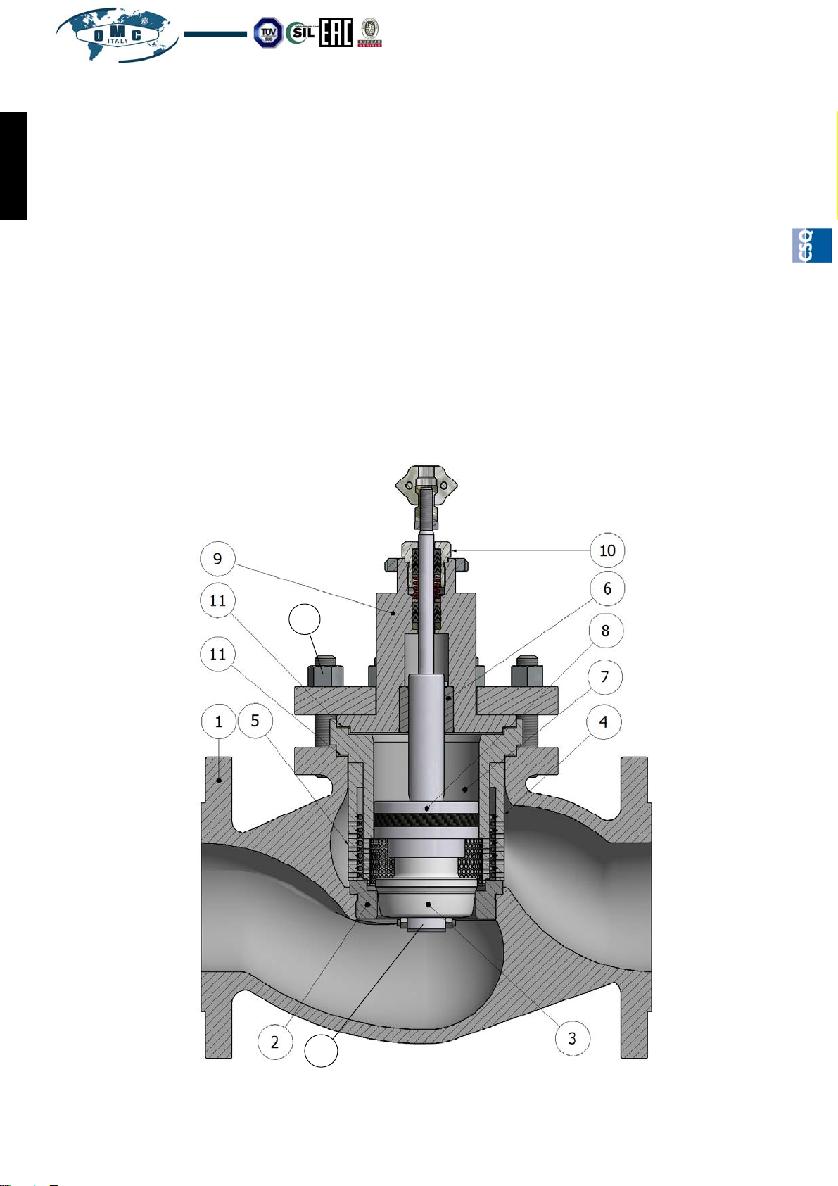
4.04 REPLACEMENT OF THE SEAT/PLUG OF THE BALANCED VALVE
By referring to Pic. 9 perform the following operations:
Separate the actuator from the valve body as described in the previous paragraph
ENGLISH
Loosen the nut (10) and fully unscrew the bolts (15).
Separate the bonnet group (9), the balancing chamber (7), the complete plug (3) and the balancing piston
(8) of the valve body (1).
Remove any cage (5)
Replace the sealing gasket of the balancing piston (8) by unscrewing the nut (16).
If required, unscrew and replace the seat (2) by using the specific wrenches
Insert in the bonnet (9) the new plug by paying attention to grease the stem with the silicone oil.
Always replace the body gasket (11) by carefully cleaning the supporting surfaces.
Re-assemble everything by repeating the operations in the reverse order by consequently paying attention
to the re-alignment of stems, seat and plug.
Gradually tighten the nuts (15) in criss-cross sequence, as indicated in the example in Pic.2 paragraph 2.01
by applying the torques indicated in chapter 5
Attention: when the plug is being replaced it is required to replace also the packing gland (see next paragraphs).
15
Page 10
16
Pic. 9 Valve with balanced plug
Our products are manufactured under ISO-9001 Quality Assurance System, approved by CSQ certified under no.9190.OMC2 - FIRST ISSUE 1994/08/04
OMC S.p.A: Via G. Galilei, 18 - 20060 - Cassina de Pecchi (MI) - ITALY - www.omcvalves.com - Tel.: (+39) 02.95.28.468
Page 11
Installaon, Operaon and Maintenance VL10/…‐en Rev.08/2018
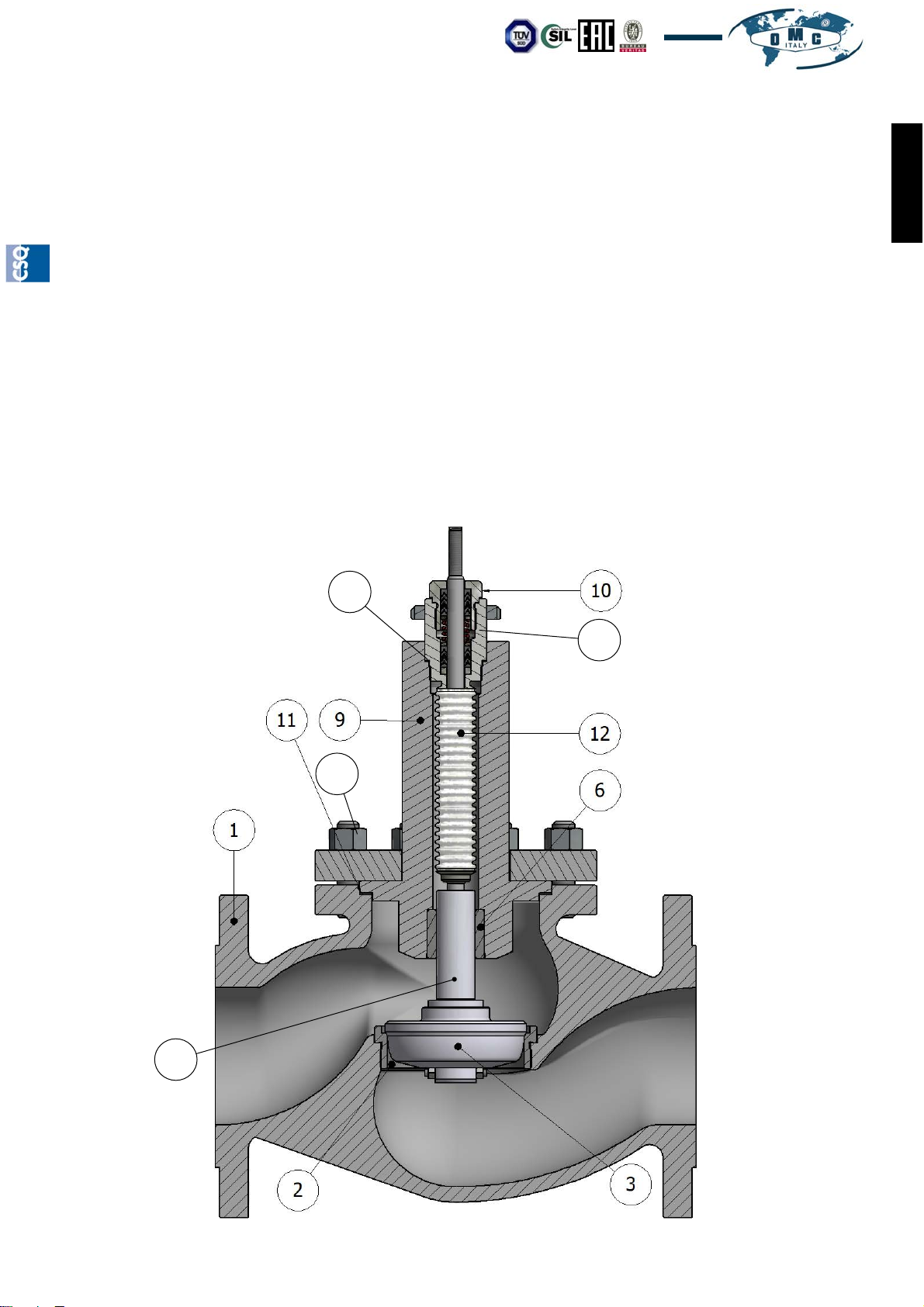
4.05 REPLACEMENT OF THE SEAT/PLUG OF THE VALVE WITH BELLOWS
By referring to Pic. 10 perform the following steps:
Separate the actuator from the valve body as described in the previous paragraph
Loosen the nut (10) and fully unscrew the bolts (15).
Separate the bonnet group (9) from the valve body (1).
Remove the complete plug (3) from the bonnet (9).
Remove the pin (17) and remove the plug (3)
If required, unscrew the bellows block (19) and replace it, by replacing also the gasket (18)
If required, unscrew and replace the seat (2) by using the specific wrenches
Insert in the bonnet (9) the new plug by paying attention to grease the stem with the silicone oil.
Always replace the body gasket (11) by carefully cleaning the supporting surfaces.
Re-assemble everything by repeating the steps in the reverse order and pay specific attention to the re-
alignment of stem, seat and plug.
Gradually tighten the nuts (15) in criss-cross sequence, as indicated in the example in Pic.2 paragraph 2.01
by applying the torques indicated in chapter 5
Attention: when the plug is being replaced it is also nessesary to replace the packing gland (see next
paragraphs).
ENGLISH
18
15
19
17
Our products are manufactured under ISO-9001 Quality Assurance System, approved by CSQ certified under no.9190.OMC2 - FIRST ISSUE 1994/08/04
OMC S.p.A: Via G. Galilei, 18 - 20060 - Cassina de Pecchi (MI) - ITALY - www.omcvalves.com - Tel.: (+39) 02.95.28.468
Pic. 10 Valve with bellows
Page 11
Page 12
Installaon, Operaon and Maintenance Manual VL10/…‐en Rev.08/2018
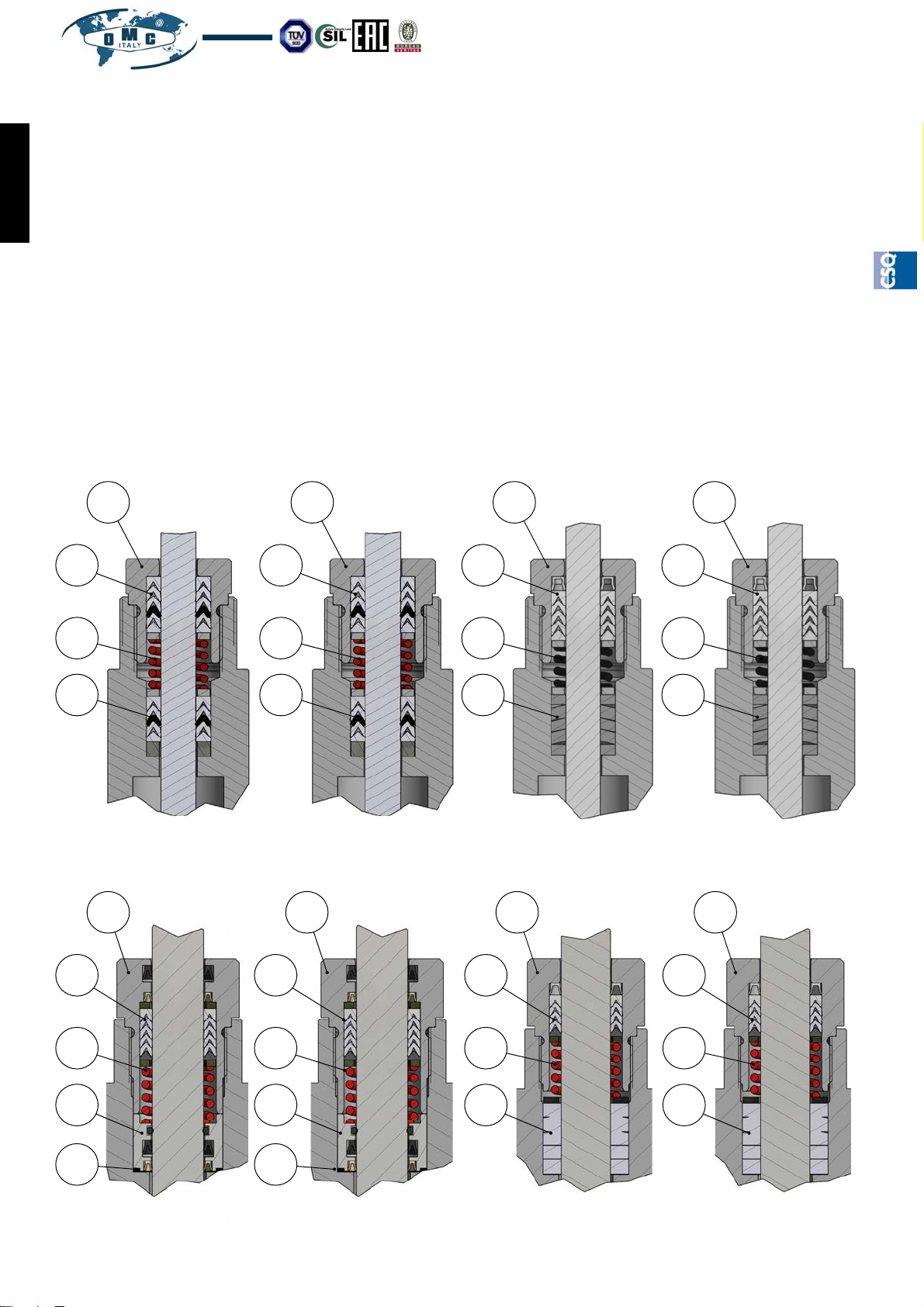
4.06 REPLACEMENT OF THE STEM PACKING GLAND
By referring to the picture corresponding to your packing gland model (from Pic 11 to Pic. 18) perfom the following
steps:
ENGLISH
Remove the plugs as described in the previous paragraphs
Fully unscrew the screw (1).
Remove the upper packing gland (2).
Remove the spring (3)
Remove the lower packing gland (4).
Replace the O-ring (5) if present
Carefully clean the housing chamber and grease it with silicone oil.
Insert the new packing gland as indicated in the picture corresponding to your model
Screw the nut (1) but not completely
Insert the plug by paying attention to grease the stem with the silicone oil.
Always replace the body gasket, and carefully cleaning the supporting surfaces.
Re-assemble everything as described in the previous paragraphs
Tighten the nut (1) as indicated in chapter 5
2
3
4
1
Pic. 11 “LP200” Pic. 12 “SP200” Pic. 13 “HP200” Pic. 14 “EcoPack 1”
1
2
3
4
1
1
2
3
4
1
1
1
2
3
4
1
2
3
4
5
Page 12
2
3
4
2
3
4
2
3
4
5
Pic. 15 “LP400” Pic. 16 “SP400” Pic. 17 “HP400” Pic. 18 “EcoPack 2”
OMC S.p.A: Via G. Galilei, 18 - 20060 - Cassina de Pecchi (MI) - ITALY - www.omcvalves.com - Tel.: (+39) 02.95.28.468
Our products are manufactured under ISO-9001 Quality Assurance System, approved by CSQ certified under no.9190.OMC2 - FIRST ISSUE 1994/08/04
Page 13
Installaon, Operaon and Maintenance VL10/…‐en Rev.08/2018
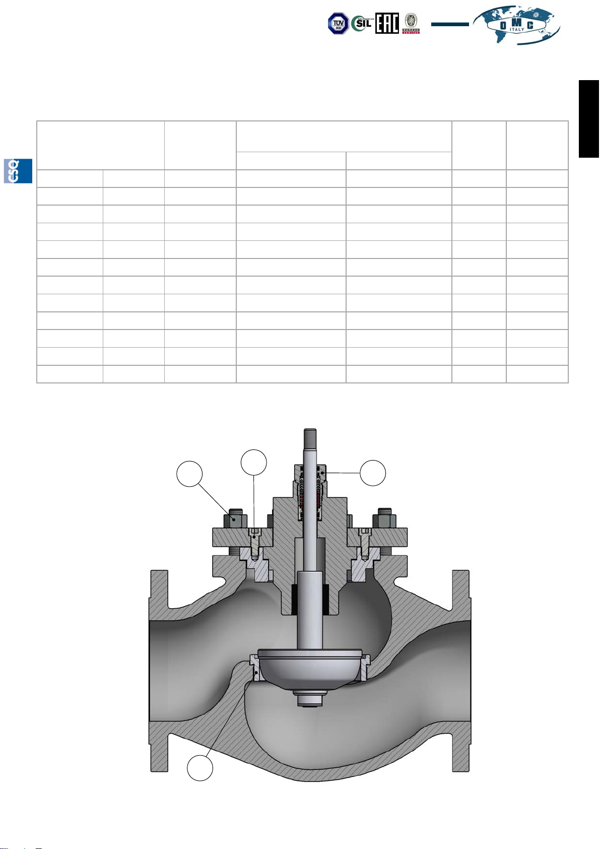
5.0 TIGHTENING TORQUES
VALVE DIAMETER
SEAT (1)
Nm ±10%
BONNET NUTS (2) Nm ±10%
VD10-KD10-KA10 KD20-KA20
SCREWS
(3)
Nm ±10%
NUT (4)
Nm ±10%
DN15 1/2” 190 30 45 // 190
DN20 3/4” 190 30 45 // 190
DN25 1” 240 30 45 // 190
DN32 1” 1/4 350 30 45 // 190
DN40 1” 1/2 550 50 85 // 190
DN50 2” 570 50 85 // 190
DN65 2” 1/2 700 100 110 // 190
DN80 3” 700 100 110 // 190
DN100 4” 850 100 110 // 190
DN125 5” 900 140 155 85 240
DN150 6” 900 140 160 85 240
DN200 8” 950 145 160 85 240
ENGLISH
2
3
4
1
Pic. 19
Our products are manufactured under ISO-9001 Quality Assurance System, approved by CSQ certified under no.9190.OMC2 - FIRST ISSUE 1994/08/04
OMC S.p.A: Via G. Galilei, 18 - 20060 - Cassina de Pecchi (MI) - ITALY - www.omcvalves.com - Tel.: (+39) 02.95.28.468
Page 13
Page 14
Installaon, Operaon and Maintenance VL10/…‐en Rev.08/2018
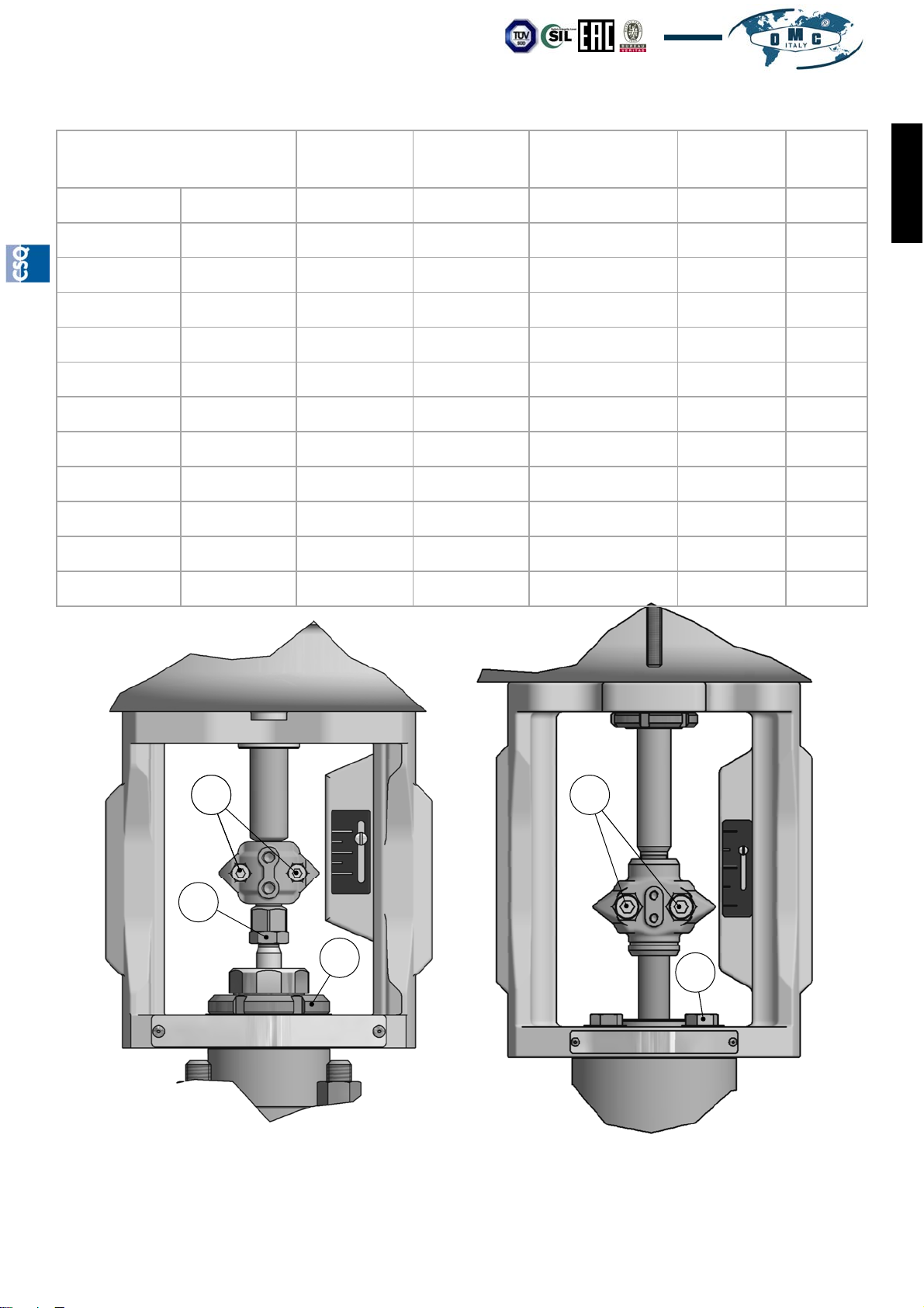
VALVE DIAMETER
NUTS (9)
Nm ±10%
NUT (6)
Nm ±10%
RING NUT (7)
Nm ±10%
SCREWS (5)
Nm ±10%
SCREWS
(8)
Nm ±10%
DN15 1/2” // 40 350 5 //
DN20 3/4” // 40 350 5 //
DN25 1” // 40 350 5 //
DN32 1” 1/4 // 40 350 5 //
DN40 1” 1/2 // 40 350 5 //
DN50 2” // 40 350 5 //
DN65 2” 1/2 // 40 480 5 //
DN80 3” // 40 480 5 //
DN100 4” // 40 480 5 //
DN125 5” 80 // // // 50
DN150 6” 80 // // // 50
DN200 8” 80 // // // 50
ENGLISH
1 5
8
6
7
9
Pic. 20 Valves DN15 ÷ 100 / 1/2” ÷ 4”
Our products are manufactured under ISO-9001 Quality Assurance System, approved by CSQ certified under no.9190.OMC2 - FIRST ISSUE 1994/08/04
Pic. 21 Valves DN125 ÷ 200 / 6” ÷ 8”
OMC S.p.A: Via G. Galilei, 18 - 20060 - Cassina de Pecchi (MI) - ITALY - www.omcvalves.com - Tel.: (+39) 02.95.28.468
Page 14
Page 15
Installaon, Operaon and Maintenance VL10/…‐en Rev.08/2018
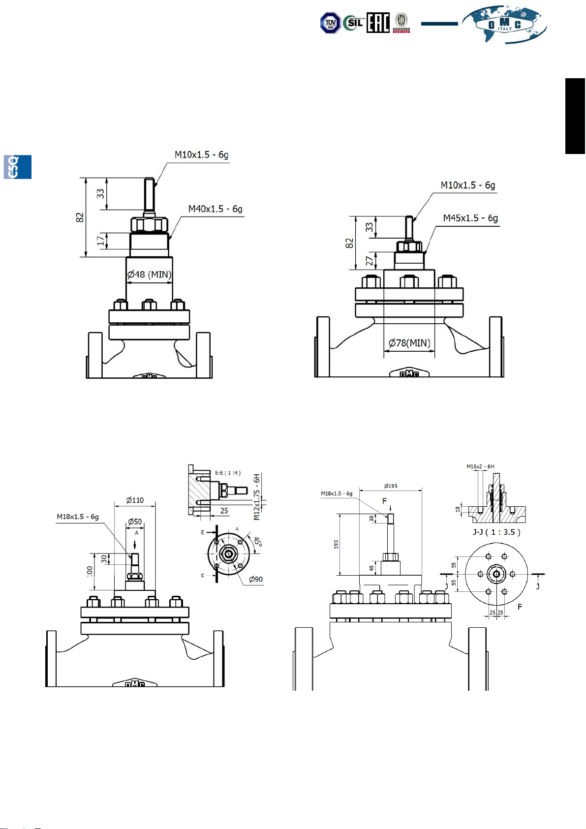
6.0 SIZES OF THE ACTUATOR CONNECTIONS
ENGLISH
Pic. 22 Valves DN15 ÷ 50 / 1/2” ÷ 2”
Closed plug
Pic. 23 Valves DN65 ÷ 100 / 2”1/2” ÷ 4”
Closed plug
Pic. 23 Valves DN125÷ 200 / 5”÷4”
VD10-KD10-KA10
Closed plug
Our products are manufactured under ISO-9001 Quality Assurance System, approved by CSQ certified under no.9190.OMC2 - FIRST ISSUE 1994/08/04
OMC S.p.A: Via G. Galilei, 18 - 20060 - Cassina de Pecchi (MI) - ITALY - www.omcvalves.com - Tel.: (+39) 02.95.28.468
Pic. 23 Valves DN125÷ 200 / 5”÷4”
KA20-KD20
Closed plug
Page 15
Page 16
Installaon, Operaon and Maintenance Manual VL10/…‐en Rev.08/2018
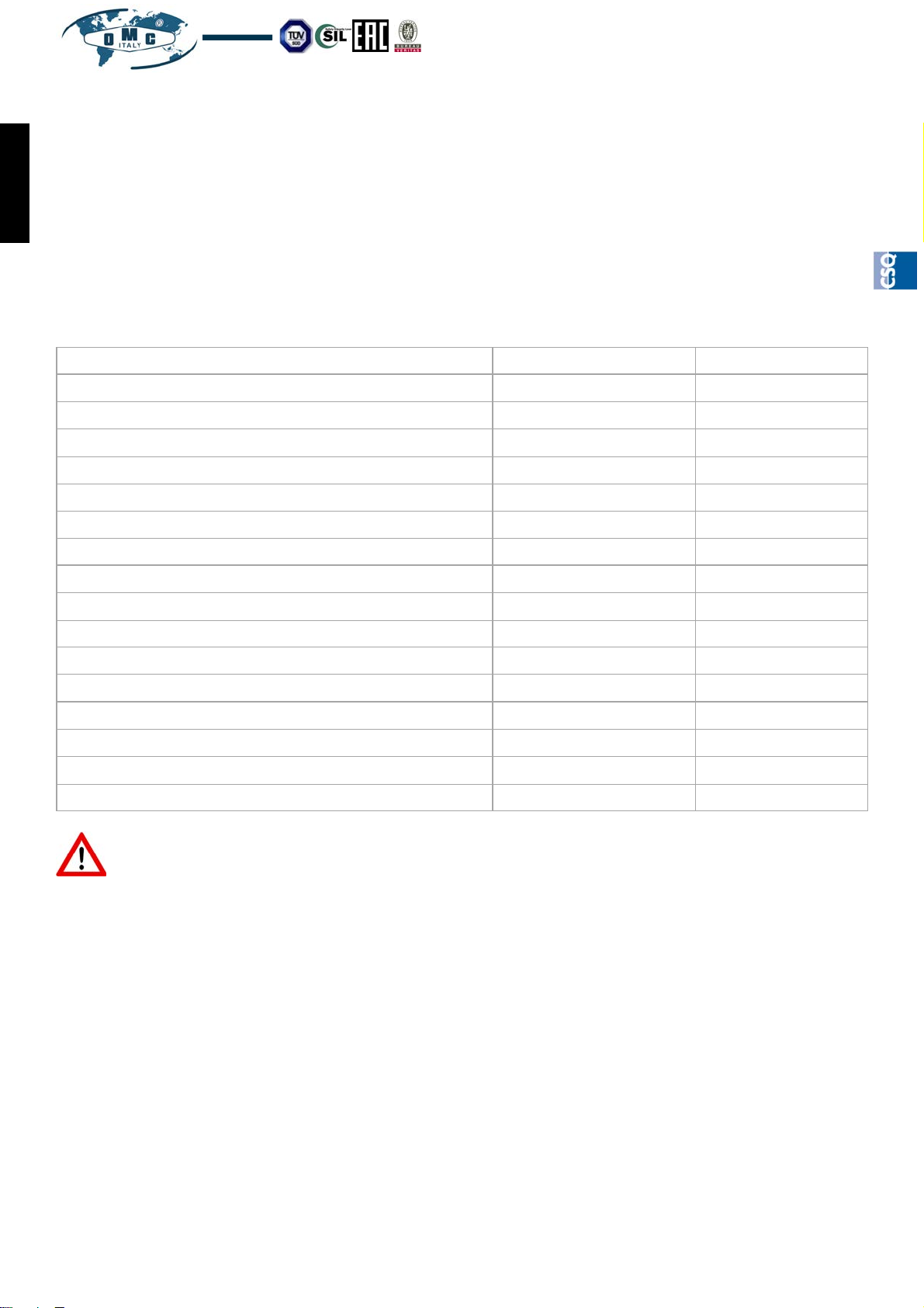
7.0 PERIODICAL CHECKS
24 hours after the first commissioning, check the connections to the pipe and especially ensure the flange bolts
are tightened to the correct torque. Inspect the valve every year by verifying its wear and replacing any damaged
ENGLISH
parts.
Periodically verify any phenomena of internal and/or external corrosion and/or erosion as they may significantly
damage the pressurized parts by locally reducing the thickness and as a consequence the safety degree.
8.0 AVAILABLE SPARE PARTS
DESCRIPTION PICTURE POSITION
Screwed seat 7 2
Plug for screwed seat 7 3
Quick-Change Seat 8 2
Plug for Quick-Change seat 8 3
Body Gasket 7 11
Gasket of Quick-Change seat 8 14
Sealing gasket of the balancing piston 9 8
ZEB20 bellows 10 12
LP200 stem packing gland 11 //
SP200 stem packing gland 12 //
HP200 stem packing gland 13 //
EcoPack 1 stem packing gland 14 //
LP400 stem packing gland 15 //
SP400 stem packing gland 16 //
HP400 stem packing gland 17 //
EcoPack 2 stem packing gland 18 //
ATTENTION!!!The OMC valves are uniquely identified by a serial number fixed on the plate located on
the actuator’s yoke. To order any spare parts or for any other need, always refer to the above-mentioned
number.
9.0 PRESSURE/TEMPERATURE RELATIONSHIP
For the pressure regression in relation to the temperature refer to the document:
- OMC-TUV-00
The actual use of the valve depends on the combination of the materials of which it is made up.
Page 16
OMC S.p.A: Via G. Galilei, 18 - 20060 - Cassina de Pecchi (MI) - ITALY - www.omcvalves.com - Tel.: (+39) 02.95.28.468
Our products are manufactured under ISO-9001 Quality Assurance System, approved by CSQ certified under no.9190.OMC2 - FIRST ISSUE 1994/08/04
Page 17
Installaon, Operaon and Maintenance VL10/…‐en Rev.08/2018
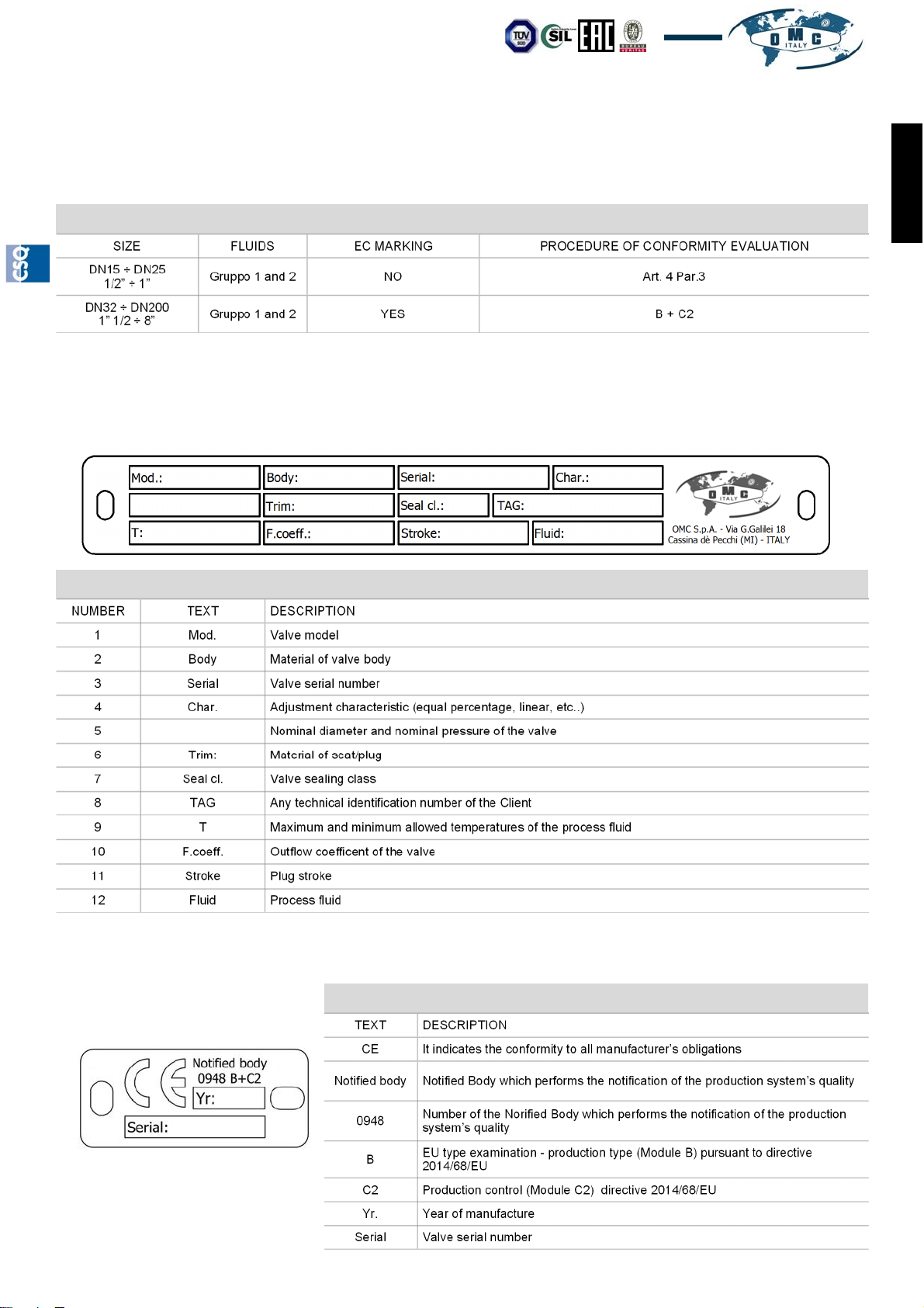
10.0 REFERENCES OF THE EUROPEAN DIRECTIVE FOR PRESSURE
EQUIPMENT 2014/68/EU
SIZE FLUIDS EC MARKING PROCEDURE OF CONFORMITY EVALUATION
DN15 ÷ DN25
1/2” ÷ 1”
DN32 ÷ DN200
1” 1/2 ÷ 8”
Gruppo 1 and 2 NO Art. 4 Par.3
Gruppo 1 and 2 YES B + C2
11.0 PLATES
11.01 IDENTIFICATION PLATES
All OMC valves are provided with an identifiction plate for the identification unique of the valve.
1 2 3 4
5
6
7
8
ENGLISH
9
10
11 12
LEGEND
NUMBER TEXT DESCRIPTION
1 Mod. Valve model
2 Body Material of valve body
3 Serial Valve serial number
4 Char. Adjustment characteristic (equal percentage, linear, etc..)
5 Nominal diameter and nominal pressure of the valve
6 Trim: Material of seat/plug
7 Seal cl. Valve sealing class
8 TAG Any technical identification number of the Client
9 T Maximum and minimum allowed temperatures of the process fluid
10 F.coeff. Outflow coefficent of the valve
11 Stroke Plug stroke
12 Fluid Process fluid
11.02 “EC” PLATE PURSUANT TO DIRECTIVE 2014/68/EU
If planned (see paragraph 10.0) the valve is provided with an “EC” plate containing the following data
Our products are manufactured under ISO-9001 Quality Assurance System, approved by CSQ certified under no.9190.OMC2 - FIRST ISSUE 1994/08/04
OMC S.p.A: Via G. Galilei, 18 - 20060 - Cassina de Pecchi (MI) - ITALY - www.omcvalves.com - Tel.: (+39) 02.95.28.468
LEGEND
TEXT DESCRIPTION
CE It indicates the conformity to all manufacturer’s obligations
Notified body Notified Body which performs the notification of the production system’s quality
0948
B
C2 Production control (Module C2) directive 2014/68/EU
Yr. Year of manufacture
Serial Valve serial number
Number of the Norified Body which performs the notification of the production
system’s quality
EU type examination - production type (Module B) pursuant to directive
2014/68/EU
Page 17
 Loading...