

OMC 1966 Snow Cruiser C-1560, 1966 Snow Cruiser C-2060, 1966 Snow Cruiser C-2065 Ownr Manual
l
HAPPY
SNOW
CRUISING
This Owner
's Manual
has
been
prepared
to
assist
you
in
the
operation
and
maintenance
of
your
new
Snow
Cruiser.
It
contain~
informatio
n that you
should
know
in
order
to
realize
the
peak
performanc
e
and
pleasure
of
operation
that
has
been
built
into
this
machine. Read
the
ent
ire
book
carefully,
then
keep
it
hanny
for
future
reference.
Your
Snow
Cruiser
is
produced umler
the
finest
quality
controlled
methods
and
built
to
give
many
hour
s
of
dependa
ble
service.
Ills
our
belief that a sa
le
does
not
com
plete
the
transaction
betw
een
the
man
-
uf
acturer
and
tile buye1·.
It est
ablishes, rathe
r , a
new
obligation--an
obligation whereby
Outboard
Ma1·ine Co
rporation
of
Canada
Ltd.
agrees
to
assist
the
buyer
in
obtaining utmost
service
from
his
Snow
Cruiser
.
W
ith
this
policy
upper
most
in
ou.r
minds,
we have appoi
nted
our
most capable Johnson,
Evinr
ude
and
Lavht-
Boy
Service Deal
ers
us
Snow
Cruiser Service
Dealers.
These
people
are
trained and
equipp
ed
to
se
rvice your
unit.
Away
from home, authorized
0 .
M.
C.
Service
Deal
ers' names
may
be
loc
ated
in
the
yellow
pages
of the
telep
hone
direct
ory
.
Outboa
rd
Marine Corporation
of Canada
L t
n.,
Peterboroug
h,
Canana
. -
r
TABLE
OF
CONTENT
S
Page
SPEC
IF ICATIONS • • • • • • • . . . . • • • • . • • . • 2
ASSEMBLY
INSTRUCTIONS
-Windshield
• • • • • • • • • • . • • • • 3
-Taillight
• • • • • • • • • • • . . • • • 3
-:::>kis
• • • • • • • • • . . • • . • • . • 3
- Tow Ba:r,
Seat
Dack &
Compartmcn
,t : • 3
-Battery.
• • • • • . • • • . • • . • . • 3
CONTROLS
-Throttle
• • • • • 4
-Warm-Up
Lever.
1
-Light Switch
• • 4
-Neutral
Shift
• • 4
-Hand
Hrake
• • 4
- Po.rking
Brllltc
• 4
-
Transmission
• 5
HOW
TO
GR'T'
STARTED
- B1·eak-In Pel'iod . . . . • . . . , • G
-
Fuel
Mixture
& Recommendations
!'i
-Mixing
Fuel
• . . • 5
-Start
ing
Engine
. . 6
-Electric
SL<u·Cing
7
-Emergency Starting
7
OP
ERATION
- E
lectric
Starting
Models 7
-Extreme
Cold
Weather
7
-Uph!ll
• • . . • • • 7
-Downhill
. • • . • • 7
-Glare
Ice
. • . . . 7
-Safety
Precautions
8
PART
No.
404278
GENERAL
MAINTENANCE
-Ca.rhuretor
-
Engine
Shroud •••••
.
-
Battery
.•.....
..
. .
-Chain & Transmission Guard
-Gas
Tank
.......•
-Dl'ive
Cha
in
Adjustment
•
-
Installing
Drive
Chain
.
-Brake
Adjustment
-T
rack
Tension
-Traek
AligrunenL
D
RIVE
BELT
REPLACEMENT
••••.
•
••••
-Procedure
for
Installing
the
Transmission
Belt
-::>tarter Motor Drive Belt • •
-Ski
Alignment
• • • • • • • •
-Off
Season
Storage
• • • . .
-After
Storing -Before
Using
TROTJRT.F. CHECK
L
IST
SERVIC
E DIAGNOSIS • •
MAINTENANCE
AND
LUBRICATIOK
ITEMS
OF
SPECIAL
INTEREST
-Repair
Service
•••••••
-Replacement
Parts
. . . . .
-Owner':;
Warranty
Certificate
•
-Where
to
Find
Model
&
Serial
Ntunber
WARRAN
TY
...••.•.•
• . •.•••
Page
8
9
9
9
9
9
10
10
11
11
12
13
13
11
14
14
14
15-16
16
17
17
17
17
. . .
..
~
18

SPECIFICATIONS
LENGTH--
107"
WI
DTH--
32"
llEIGHT --40-1/4" (33-1/1" less
windshield)
ENGINE--
OMC
2-cycle
oppo
sed
twin
RATING - -
Maximum
14
HP
A.t
4500
rpm
SPEED
--
30
mph
pl
us
S
TARTER-
-
Model
15
60 --Manua
l r
ewi!ld
Model 2060 --Marrual r
ewind
Model
2065 --Electric
and
manual
rewind
CLU
TCH - -
Centrifugal
-ope1·
ated
sheave
engages belt
DRIVE -Torque
Sensitive, Vari.
a
bl
e Speed, V-
belt
and
chain
.
TRANSMISSION
--
Variabl
e -
speed,
3:1
to
1:1
rati
o
NEUTRAL
LOCK-0UT --Neu-
tral
l:)Ck
for
starts and
WP.rm-
ups
MUFFLER
--
Eng
ine
muffl
er
for
quiet
op
et'atio:~.
BRAKE
Disc
type,
h~J
H"l
OpAl'-
ated
TRACK
Speci:l
lly
rtesigne<i
flexible tr
ack
,
fully
adj
ustable
WIDTH
Model
1560 --15.5
In.
Model 2060 --20.6 In.
Mod
el 2065 --20.5 ln.
SKIS --Formed steP.
I,
equipped
vn
th
shock-absorblng
leaf
FIGURE
I
spr
ings
Rnrt
replaceab
le
wear
run."lers
SEATING--
Two
adults, vin
yl
coated
t
wU!
cover, molded
ure-
thane
foam
cu::;hion
SHROUD
--
Mo
lded
fihergl
as~
with
built-in headli
ght
FUEL
TANK
--
Capacity
4.5
Imp.
or
5
.4
U.S.
gallo:~.s
FUEL MIXT
URE-
16:1 nsing SAE
30
Oil
IGNITION
BREA
:<ER POIN1'
GAP--
.020
SPAR
K
PLUG
AND
GAP
- -
Champion
JSJ
or
equival
ent
-
.0
21'
"
gap
2
ASSEMBLY
INSTRUCTIONS
All small
parts
are
pack
ed
in
r
e.a
r e
(}m-e
r
&:tppo
rt
of
pack.
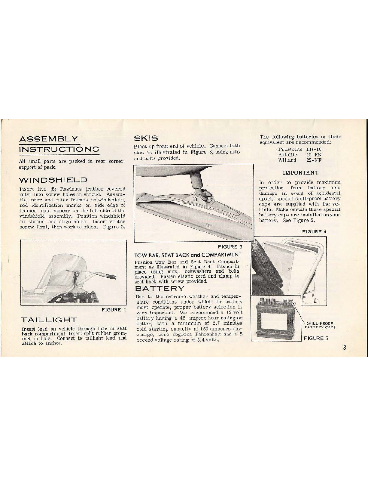
WINDSHIELD
Insert
five
(5)
Rawlnuts
(rublJer
euveret.l
nuts) into
screw
holes in sh!"oud.
Assem-
t.le i
nner
llnrl
oute
:r
framP.~
o"\ windshiP.ld,
re d
idcntificlltion
mar
ks
on
cide
edge
o:
frames
must
appear
on •.ha
left
side
uf
the
windshield
assembly. Posit
ion windshield
on
shrourl
::lnci ali
gn
holes. lnsP.l't
cP.ntP.r
scre
w f i
rst,
then
work
to
s i
des
. Fig.1re
2.
FIGURE
2
TAILLIGHT
Insent lead on vehicle through hole
in
se•at
hack compartment. Insert split rubber grcm-
me
.t
in
hole. ConnP.d to taillight
le
•ad and
a-ttach
to
anchor.
SKIS
BlOCk up
fron
t end
of
vehicle.
COIUtect
b
oth
skis
as
illustrated
in
Figure
3,
using
nuts
and
bolts ?rovided.
FIGURE
3
TOW
BAR, SEAT
BACK
and
COMPARTMENT
Position
Tow
Bar
and
Sea-t
Dack
Compart-
m
em
a-s
illus•trat~d
i.u
Figure
4.
F.as.
ten
in
pbace us•ing
nuts
, Lockwashers
and
oo·l!>S
provided.
Fasten
ela.s
tic cord
and
cl
amp
to
sea•t
back
with screw provide
d.
·
BATTERY
Due
to
the
cxtxcmo
wco.ther
and
tem
per-
ature
conditions
under
which
the
JJattery
must
operate,
proper
battery
select
ion
i:s
very
ir.1.portant.
We
recommend
8 1 2
vo
lt
battery haY
ing
a.
42
ampere
hour
ro.ting
or
better,
with a minimum
of
2.7 rninuLeo
cold
starting
capacity
at
150
amperes
dis
-
charge,
zero
degrees
Fahre:1.heit
and
11.
!1
second
voltage rating
of
8.4
volts.
The
following
battexies
or
their
equivalent
are
recommended:
I'rcsto!ite
HN-10
Autollte
10-HN
Willard
22-NF
IMPOR
TANT
ln
o:rr1P.
:r
to
provide
maxim:~m
protection
fr
om
battery
acid
darmtge
in
eve:1t
of
accideutul
upset
, sp
ecial
spill-proof
ba:tery
~
aps
ll.l'P.
supplied
with
the
ve-
hicle.
Make
certain these
special
JJa·
.tery
cuvs are
iuolall
ed
onyouL·
battery.
See
Figure
5.
FIGURE
4
3
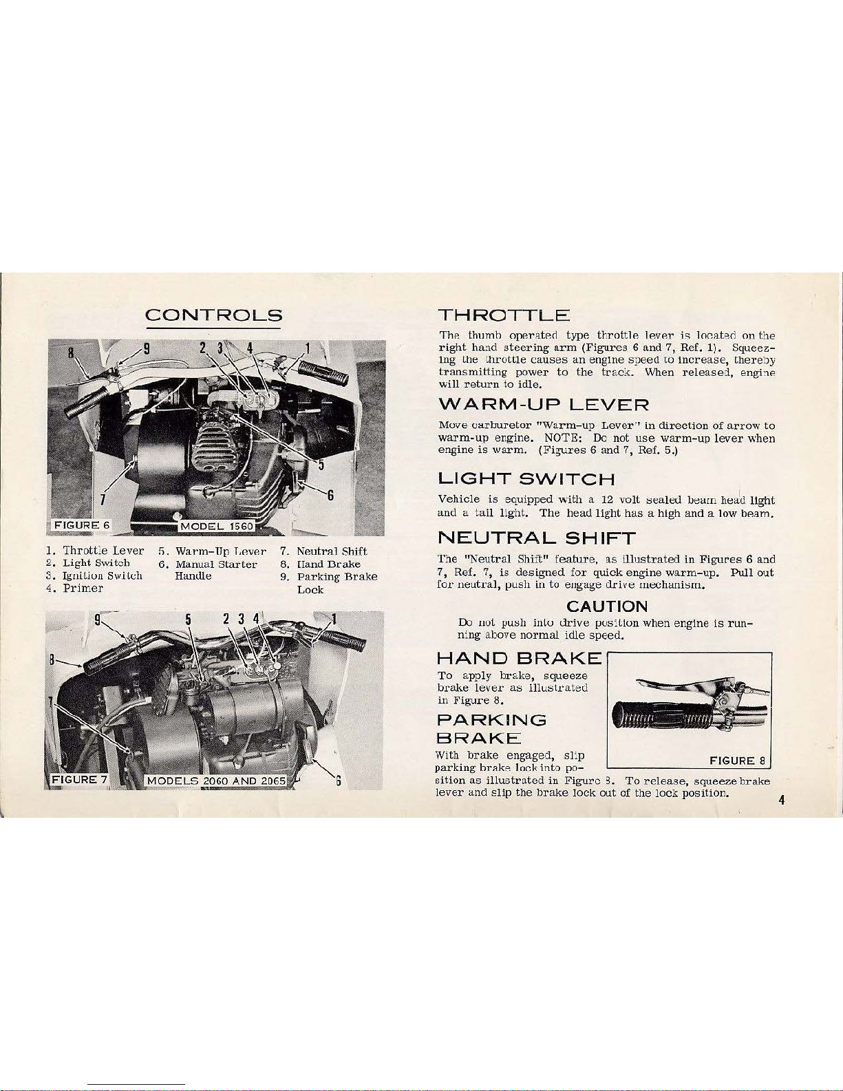
1.
Thrott~e
Lever
2.
Lig
ht
Switch
3 . Igniliuu
Swlich
4.
Primer
CONTROLS
5.
Warm-Up
T.P.v
er
6.
Manual
Starter
Handl
e
Neutral
Shift
!land
Drake
Parking
Bra
ke
Lock
THROTTLE
'The
thumb
operatP.ct
type
throttle
lever
j,:;
lo~fl.te
d
on
the
right
ha:~.d
steering
arm
(Figures
6
and
7,
Ref.
1).
Squeez:-
tng
Lhe
t
hrottle
causes
an
engine
speed
to
increase,
there
by
transmitting
power
to
the
trac
:, . When rel
eased,
enghe
will
return
to
idle
.
WARM-UP
LEVER
Move
Cll.rburetor
"Warm-up
Lever·•
in
direction
of
arrow
to
warm-up
engine.
NOTE:
Do
not
use
warm-up
lever
when
engine
is
warm. (Figures 6 and
7,
Ref.
5.)
LIGHT
SWITCH
Vehicle
is
equipped
''•iith a 12
volt
sealed
!Jearn heJu
light
and
a t
ail light.
The
head
light
has a high
and
a low bP.am.
NEUTRAL
SHIFT
T
he
"Neutr
al
Shift"
feature,
as
illustrated
in
Figures 6 and
7,
Ref. 7,
is
designed
for
quick
engine
warm-up.
Pull out
for
neutral,
push
in
to
eugage
drive
1!lechani::;m.
CAUTION
D:>
uoL
.fJU::>h
inLo
drive position
when
engine
is
run-
ning
abo
ve
normal
idle
speed.
HAND
BRAKE
To
apply
brake,
squeeze
b!·ake
lever
as
illustL·ated
in
Figure
8.
PARKING
BRAKE
With
brake
engaged,
s lip
FIGURE
8
parking
brake
lock into
po-
sition
as
illustrated
in
Figure
3.
To
release, squ
eeze
brake
lever
and
slip
the
brake
lock
out
of
the
lock
position
.
4
 Loading...