

OMAS Air-Fi AFT7, Air-Fi AFT9, Air-Fi AFT77 DUAL, Air-Fi AFT99 DUAL Installer And User Instruction Manual
Page 1
CLIMATIZZATORE DA PARETE CON POMPA DI CALORE
WALL TYPE AIR CONDITIONER WITH HEATING PUMP
MANUALE DI INSTALLAZIONE E USO
INSTALLER AND USER INSTRUCTION MANUAL
GAS REFRIGERANTE R410A
COOLING GAS R410A
Page 2

1. GENERAL INFORMATION
1.1 GENERAL ADVICES
1.2 RECEIVING THE PRODUCT
1.3 HANDLING
1.4 OPERATING CONDITIONS
1.5 DISPOSAL OF THE PRODUCT
2. INSTALLATION
2.1
CHOOSING THE AIR FLOW DIRECTION
2.2 WHERE TO INSTALL THE AIR CONDITIONER
2.3 INTERNAL UNIT INSTALLATION
2.4
2.5
PREPARING THE COOLING LINES
CONNECTING THE PIPES ON THE INTERNAL UNIT
2.6 EXTERNAL UNIT INSTALLATION
2.7 REFRIGERANTS CIRCUITS
2.8
INDOOR/OUTDOOR UNIT MULTIFILAR WIRING DIAGRAM
2.9 EXTERNAL UNIT CONNECTION PIPES
2.10 VACUUM AND FILLING OPERATION
3. USE AND MAINTENANCE
3.1 REMOTE CONTROL FUNCTIONS
3.2 INSTRUCTIONS FOR USE
3.3 RESET OPERATION
3.4
3.5
MAINTENANCE
PROBLEM - POSSIBLE CAUSES / REMEDIES
ENVIRONMENTAL INFORMATION : this equipment contains fluorinated
greenhouse gases covered by the Kyoto Protocol. It should only be serviced or
dismantled by professional trained personnel.
GAS R410A,GWP( GlobalWarming Potential ) = 1975
INDEX
Page 3

1 GENERAL INFORMATION
1.1 GENERAL ADVICES
After having removed the packing, check that all the
content is intact and complete. In the event of noncompliance, contact the Retailer which sold you the
appliance.
The appliance should be installed and the
maintenance should be effected by a qualified
Company in accordance with the laws and
regulations in force in the country of installation.
Upon work accomplishing, this Company should
issue the owner the declaration of compliance of
installation with current regulations and standards
and with instructions given on this booklet.
These appliances have been designed to heat or
cool the air of rooms and should only be used for this
purpose, in compatibility with their performances
features. The manufacturer cannot be held liable for
damage caused to property or injury to persons or
animals due to incorrect installation, regulation and
maintenance or to improper use.
This air-conditioner contains R410-A refrigerant : at
the end of its use, operate with caution during the
disposal, in order to not damage the cooling
connections and the battery.
Do not switch on the unit before having totally
assembled it and before having put it in its correct
operating position.
Before starting the appliance, check that it is
correctly earthed, according to the legislation in force
in the country concerned.
BASIC SAFETY RULES
Using electrical appliances implies the observance of
basic safety rules, such as those given below:
Children and unassisted handicapped persons are
not allowed to use the air-conditioner.
Do not touch the air-conditioner when foot or parts
of the body are wet or damp.
Do not carry out any cleaning operation until the airconditioner has been disconnected from the mains
electricity supply by putting the installation on/off
switch to “off”.
Do not pull, remove or twist the electric cable
connected to the air-conditioner, even if
disconnected from the mains electricity supply.
A too low temperature is harmful to health as well as
being a useless waste of energy.
Avoid prolonged direct contact with the flow of the
air. Avoid the room being closed for a long time.
Periodically open the windows to guarantee a correct
change of air. During storms put the on/off switch to
“off” position.
This instruction booklet is an integral part of the
appliance and should be therefore carefully
preserved and always accompany the appliance,
also in the event of transfer to another owner or user
or another installation. Should the booklet be
damaged or lost, please request a copy to your
Technical Assistance.
Repair or maintenance works must be carried out by
Technical Assistance or by qualified technicians in
compliance with the instructions given in this booklet.
Do not alter the appliance, since hazardous
situations could be created while the manufacturer of
the appliance will not be liable for any damage or
injury caused.
Before staring the installation it is suggested to
foresee an omnipolar switch, fixed in accessible
position, with contacts opening distance equal or
superior to 3 mm.
This machine has been submitted to a 40MPa
testing pressure.
Do not sit or stand on the appliance or put anything
at all on top of it.
Do not spay or throw water directly into the airconditioner.
Do not introduce sharp or pointed objects through
the air intake or outlet grids.
Do not access internal parts of the air-conditioner
without having put the on/off switch to “off” position.
Do not leave the packing material ( cardboard,
staples, plastic bags, etc..) to be taken by of children,
but dispose it properly since it could be a source of
danger.
Do not alter the safety or regulating devices without
the permission and instructions of the air-conditioner
manufacturer.
ENGLISH -2-
Page 4
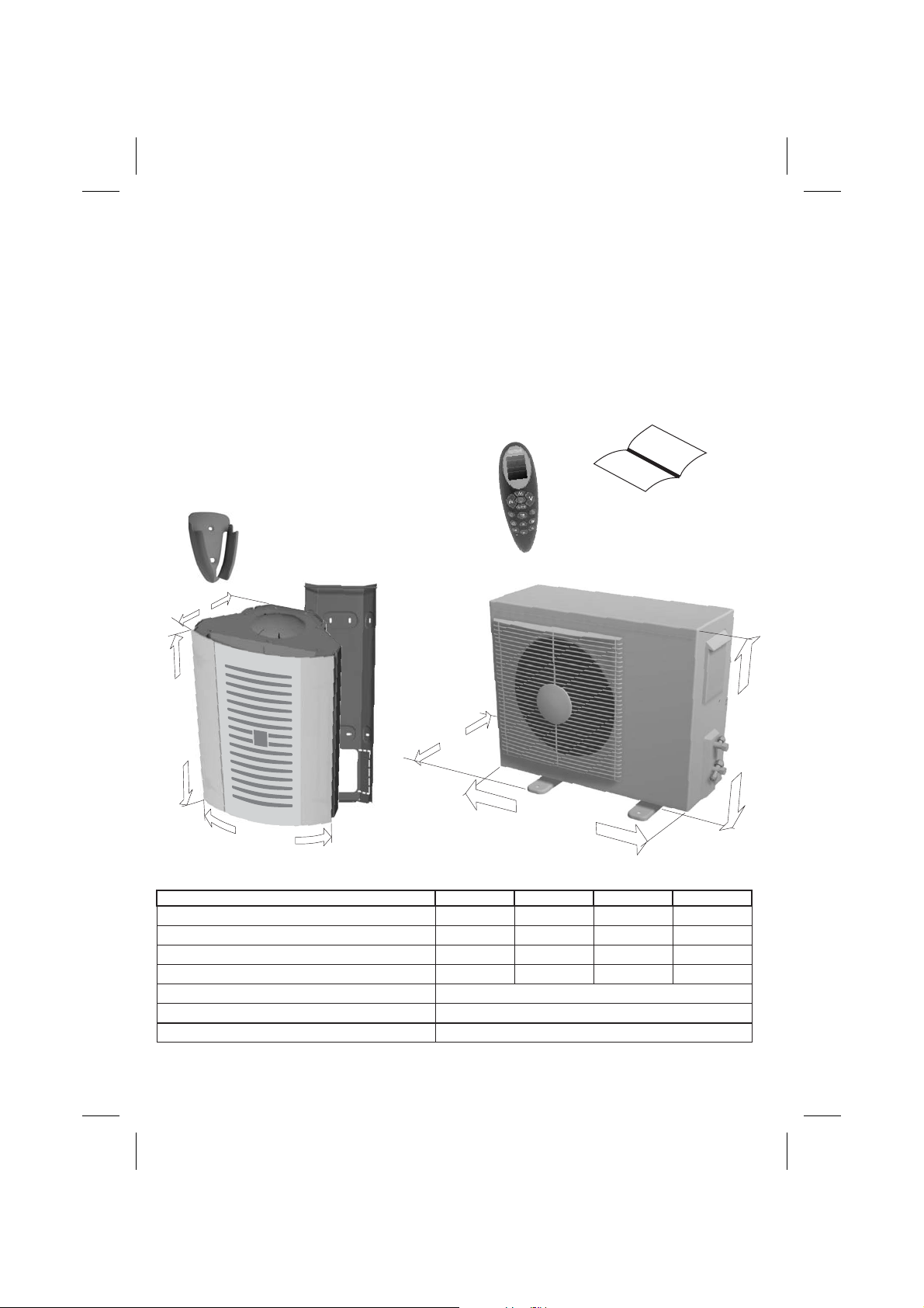
1.2 RECEIVING THE PRODUCT 1.3 HANDLING
The air-conditioner is delivered in two different
packings protected by card-board and is
accompanied by:
- Instruction booklets.
- Wall-mounting support.
- Supplied accessories for installation
operation.
- Remote control.
- Connection pipes.
- Drainage pipes
- Electrical connection cables.
Packaging components must be disposed
correctly and not left without control to
children, since they are a potential source
of danger
REMOTE CONTROL WALL
MOUNTING SUPPORT
WALL MOUNTING SUPPORT
D
The air-conditioner should be handled by
technical staff using suitable equipment for
the appliance weight.
It is advisable to remove the packing only when
the air-conditioner has been located in the point
of installation.
During transportation the outdoor unit must be
kept in UPRIGHT position.
USER AND INSTALLER
BOOKLET
REMOTE CONTROL
H
W
INTERNAL UNIT
Model
Internal unit dimensions H/W/D(cm)
Internal Unit weight (Kg)
External Unit dimensions H/W/D(cm)
External Unit weight (Kg)
Rated voltage (V)
Cooling gas
Additional cooling gas per each meter ( more than 5m ) g/m
D
W
EXTERNAL UNIT
AFT7
54,5/35/25
7,1 7,1 7,1
49,5/67/30
27,5 28,5 52
ENGLISH -3-
AFT9
54,5/35/25 54,5/35/25
49,5/67/30
220-240
R410 A
20
AFT77 DUAL
61/91/34,5
H
AFT99 DUAL
54,5/35/25
7,1
61/91/34,5
53
Page 5
1.4 OPERATING CONDITIONS
COOLING MODE
- Internal temperature from 18°C 47% R.H. to 32°C 47% R.H.
- External temperature from 18°C 41% R.H. to 43°C 41% R.H.
HEATING MODE
- Internal temperature from 18°C 47% R.H. to 27°C 47% R.H.
- External temperature from -5°C to 24°C 41% R.H.
1.5 IMPORTANT INFORMATION FOR CORRECT DISPOSAL OF THE
PRODUCT IN ACCORDANCE WITH EC DIRECTIVE 2002/96/EC
.
At the end of its working life, the product must not be disposed of as urban waste.
It must be taken to a special local authority differentiated waste
collection centre or to a dealer providing this service.
Disposing of a household appliance separately avoids possible negative
consequences for the environment and health deriving from inappropriate
disposal and enables the constituent materials to be recovered to obtain
significant savings in energy and resources.
As a reminder of the need to dispose of household appliances separately,
the product is marked with a crossed-out wheeled dustbin.
BS PLUG WIRING
Wiring Instructions: Should it be necessary to change the plug please note the wires in the
mains lead are coloured in accordance with the following code :
BLUE - NEUTRAL
BROWN - LIVE
GREEN AND YELLOW - EARTH
As the colours of the wires in the mains lead of this appliance may not correspond with the
coloured markings identifying the terminals in your plug, proceed as follows:
1. The wire is the and must be connected to the terminal which is marked with
BLUE NEUTRAL
the letter or coloured .
2. The wire is the and must be connected to the terminal which is marked with the
letter or coloured
3. The is the and must be connected to the terminal which is marked
with the letter or or coloured .
4. Always ensure that the cord grip is positioned and fastened correctly.
If a fused plug is used it must be fitted with a fuse.
If in doubt consult a qualified electrician.
Wiring for a 13 Amp Plug (BS1363)
Please note. The Earth Terminal is
Marked with the letter or Earth Symbol .
N BLACK
BROWN LIVE
L RED.
GREEN/YELLOW EARTH
E GREEN OR GREEN/YELLOW
13A (BS 1363) 13A
E
Earth(Green/Yellow)
13 AMP
ENGLISH -4-
Neutral - N
(Blue)
Live - L
(Brown)
Page 6
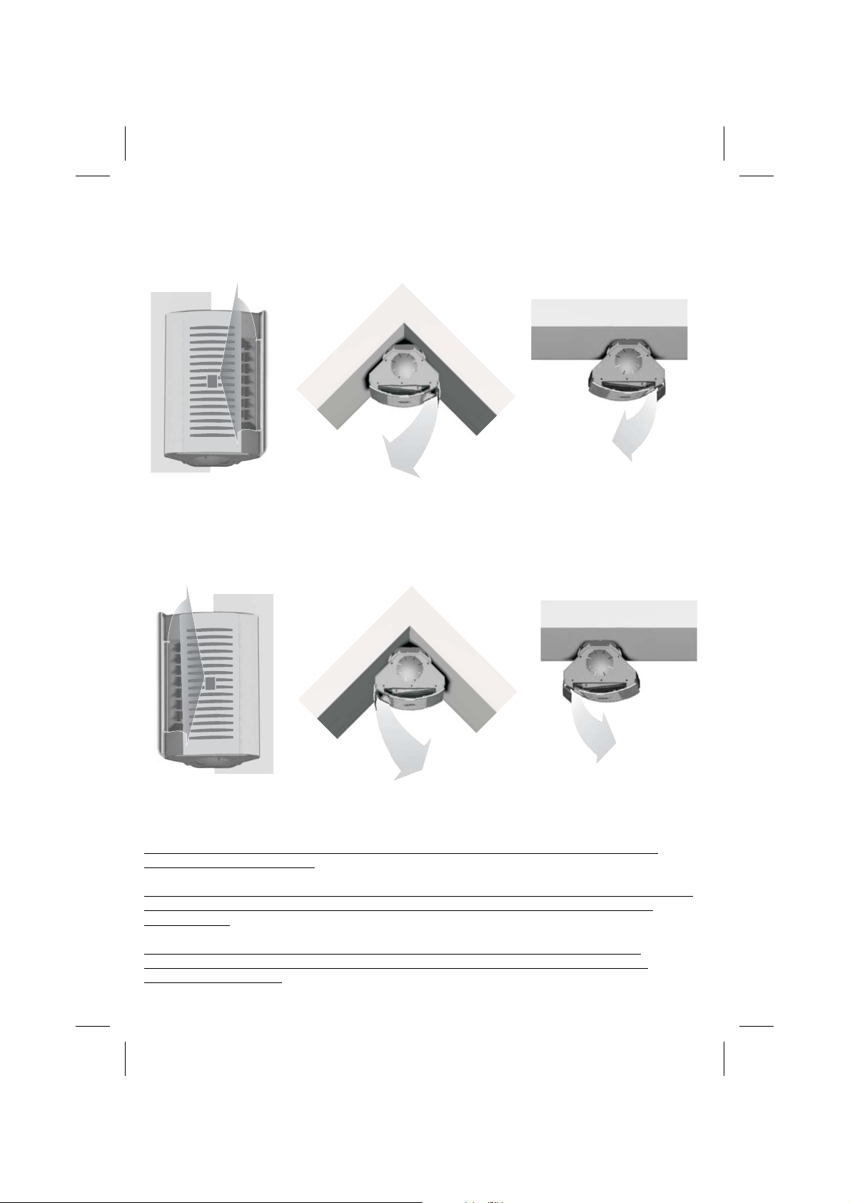
2.1 CHOOSING THE AIR FLOW DIRECTION.
THE UNIT IS SUPPLIED WITH THE AIR FLOW EXIT POSITIONED IN THE RIGHT SECTOR:
THIS ALLOWS THE AIR DIFFUSION FROM RIGHT TO LEFT SIDE.
IN CASE THE USER WANTS TO MODIFY THIS STANDARD AND DIRECT THE AIR DIFFUSION
FROM LEFT TO RIGHT SIDE
FOLLOW THE INSTRUCTIONS CONTAINED INSIDE THE INSTALLER PARAGRAPH.
ATTENTION: THESE OPERATIONS CAN BE EFFECTED ONLY BY A QUALIFIED AND
AUTHORIZED TECHNICIAN.
FOR SAFETY AND PRACTICAL REASONS, WE SUGGEST TO ANALYSE THE POSSIBILITY
OF MODIFYING THE AIR EXIT DIRECTION BEFORE STARTING THE INSTALLATION
PROCEDURE.
IF THE MODIFICATIONS NECESSARY TO CHANGE THE AIR EXIT OCCUR AFTER
INSTALLATION, BEFORE STARTING THE OPERATION ALWAYS DISCONNECT THE
ELECTRICAL SUPPLY.
ENGLISH -5-
Page 7
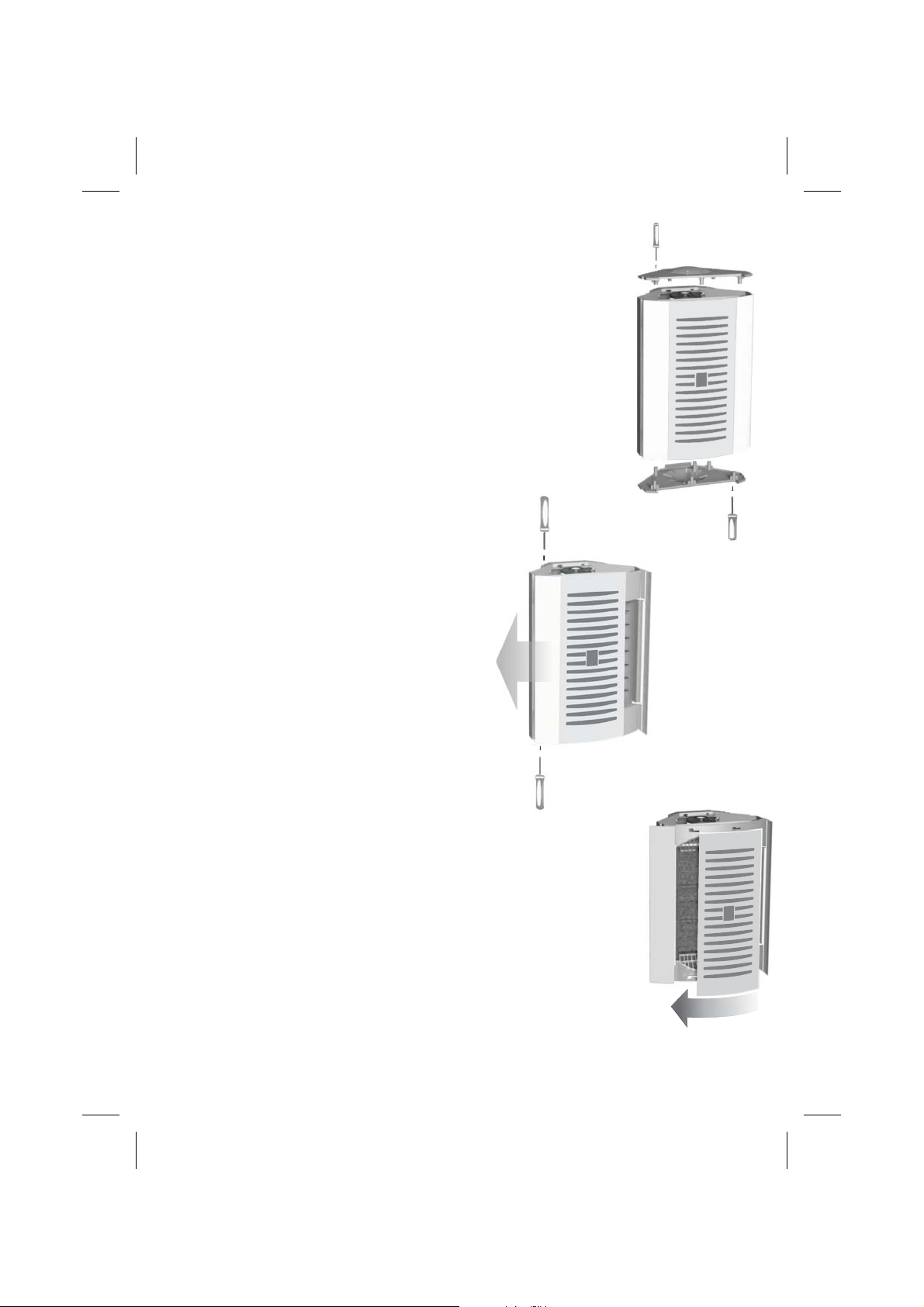
!
Remove the screws that fix the upper and lower
closing caps.
!
Remove the screws that fix the left side frontal
panel on the upper and lower part of the indoor unit.
!
Extract the front panel by pulling it out.
!
Remove carefully the central panel, by rolling it
from right to left side.
ENGLISH -6-
Page 8

!
Remove the screws fixing the display
support and rotate it of 180°. Pay attention to
place in the correct position the electrical
cables.
!
Position the display back by using the
screws previously removed. Rotate the indoor
unit of 180°, by maintaining the air exit on the
left side.
!
By maintaining the front panel with the brand
plate in the lower part, insert it back by rolling
it from right to left side.
!
Both the pipes located in the rear part of the
indoor unit must be rotated up to 180°:
!
Remove the 4 screws (A) that fix the plastic
protection covering the cooling circuit.
A SPECIAL ATTENTION SHOULD BE PAID
DURING THE FOLLOWING STEPS :
!
Take the indoor unit pipes out of 15°
(PHASE 1)
(A)
!
Rotate the terminal part, gently, up to 180°,
avoiding possible bendings on the curve
(PHASE 2) by maintaining the pipes blocked
in the (B) position.
The internal unit is equipped with condense
drainage connection option both on the upper
and lower part. If the air exit position should
be changed, the condense drainage position
must be modified too : take the pipe and the
plug positioned on the drainage connection off
and then invert their position.
!
Put all the removed platics parts back to their
original position and fix them with the screws.
!
Position the indoor unit on the upper part of
the wall mounting bracket and rotate it up to
45°.
After these operations the air conditioner is
ready to be installed with air exit located on its
left side.
ENGLISH -7-
Page 9

IMPORTANT:
To not compromise the air-conditioner integrity, do not install it among windows or doors.
If this installation is however necessary, put a stop system on the door/window, in order
to avoid any inconvenience.
·
To not compromise the operating of the air-conditioner, do not install it near curtains or
similar
ENGLISH -8-
Page 10

2.2 SELECTING THE LOCATION
The place of installation should be arranged by the
installation designer or by a technically competent
person and should take into account technical
requirements as well as relevant current laws and
regulations which envisage the obtaining of specific
permits (e.g. town-planning, architectural, fire,
environmental pollution regulations, etc. ); it is
therefore advisable to apply for and obtain the
necessary permits before installing the airconditioner.
The air-conditioner should be installed by a qualified
Company in compliance with relevant laws and
regulations in force inthe country of installation.
Before starting installation take intoconsideration:
- The position of the indoorandoutdoor unit,
- The minimum technicalspaces,
- The maximum lengthof the refrigerant lines
- The difference inlevel between the appliances
- The presence ofother heating sources.
- The possibility of draning the moisture.
.
2.3 INTERNAL UNIT INSTALLATION
The wall-mounting support allows two different
solutions:
A) Wall mounting installation
B) Corner area installation.
A) WALL MOUNTING INSTALLATION
!
Unscrew the two screws in the inferior part of the
unit to remove the wall mounting support (Fig.1)
!
Lean on the wall the support, in the foreseen
installation area, check the level and the distances
(Fig.2)
!
Mark with a pencil inside the fixing holes
(B). (Fig.2)
Remove the support.
!
Make two holes in correspondance to the pencil
!
marks.
If the pipes have to pass through the wall in X
!
direction (Fig.4), drill a hole ø 70/80 mm inclined of
3-5° downward in correspondance to the (B)
area (Fig.2).
If the direction is Y, (Fig.4), take away the pre-
!
sheared metal part, in the selected direction.
!
In case the upper pre-shared part should be
removed too, the mounting bracket must be fixed
through the holes located in C position and the
supplied washers must be interposed between the
bracket and the wall.
Fix the support through the 4 screws anchors and
!
the provided screws.
Avoid bending the copper pipes several times in
the same point, otherwise they could be
damaged
(Fig.3),
only
.
(A) and
ENGLISH -9-
ceiling
90°
20 cm
(A) (A)
20 cm 20 cm
wall
(A) (A)
180/200 cm
floor
X
Y
(C)
Fig.1
wall
(B)
Fig.2
3-5°
Fig.3
Y
Fig.4
Page 11

B) CORNER INSTALLATION
!
Unscrew the two screws in the inferior part of the
unit to remove the wall mounting support (Fig.1)
!
Lean on the wall the support, in the foreseen
installation area, check the level and the distances
(Fig.2)
!
Mark with a pencil inside the fixing holes
(B). (Fig.2)
Remove the support.
!
Make two holes in correspondance to the pencil
!
marks.
If the pipes have to pass through the wall in X
!
direction (Fig.4), drill a hole ø 70/80 mm inclined of
3-5° downward in correspondance to the (B)
area (Fig.2).
If the direction is Y, (Fig.4), take away the pre-
!
sheared metal part, in the selected direction.
In case the upper pre-shared part should be
!
removed too, the mounting bracket must be fixed
through the holes located in C position and the
supplied washers must be interposed between the
bracket and the wall.
Fix the support through the 4 screws anchors and
!
the provided screws.
Avoid bending the copper pipes several times in
the same point, otherwise they could be
damaged
(Fig.3),
only
.
(A) and
Fig.1
ceiling
20 cm
Corner area
(A) (A)
(A) (A)
3-5°
Fig.3
ENGLISH -10-
180/200 cm
floor
X
(B)
Fig.2
(C)
Y
50 mm
Fig.4
Page 12

2.4 PREPARING THE COOLING LINES:
- The cooling lines between the two units should be in
special copper pipes forcooling installation.
- Check the internal part of the pipes and eventually
remove dirt or dampness as they can interfere with
proper operation.
- The cooling lines should be singularly insulated with
polyurethane foam with closedcells.
- Plan theroute of thepipeline to reduce the length and
the number of bends as much as possible for best
performance of the system.Alwaysuse a pipe folder.
- After having cut the connection pipes, eliminate the
slight defects by maintaining the pipe opening
downward.
- For a correct flange operation, use a flange tool for
pipes and eliminate the eventualdefects.
- Check that the flangesdo not have anydefect.
- Removethe connectionslocated onthe indoorunit. A
little quantity of air will be expelled to show the good
condition of the circuit.
Not correct !
Correct !
- Screw andtighten the pipe unionwith manometric key
as per the followingdata:
OUTSIDE DIAMETER THIGHTENING COUPLE
mm
ø 6,35
ø 9,52
Inch
¼”
3/8”
Kg/m
1,8
4,2
During this operation keep the connections with
another key in order to avoid possible pipes twistin
g.
Attention:
Check the flanging with the above mentioned
images.
If the section is not correct, cut it away and
proceed with another one.
ENGLISH -11-
Copper
tube
1,3/2mm
Page 13

2.5 CONNECTING THE PIPES ON THE
INTERNAL UNIT
Hook the unit on the wall mounting support, by
matching intoAB.
Line up the pipes of the indoor unit together with the
ones of the outdoor unit and screw manually the
unions.
DO NOT FORCE THE SCREWING WITH TOOLS IF
THE LINE UP OPERATION ON THE THREAD
PARTS IS NOT PERFECTLY EFFECTED.
Then, tighten with the help of a dynamometric key by
respecting the details quoted in the previous page.
Put then the pipe insulating back to its position and
complete the operation by adding polyethylene tape.
It is advisable to insulate the moisture drainage pipe
with the cooling pipes in order to have the pipes all
together in one block (FIg.3).
B
A
Position back the unit and fix it on the wall mounting
support with the fixing screws placed in the bottom
part (Fig.4).
ENGLISH -12-
Page 14

CONDENSE DRAINAGE
The indoor unit is fitted with condense drain pipe
which a drainage hose ( inside 16 mm) should be
connected, leading to a suitable drainage outlet area.
Fasten the condensate drain pipe to the refrigerant
pipes with adhesive tape whenever the lines cross
through a wall; this is to prevent the condensate drain
pipes from being crushed.
The drainage pipe should have a 3-5° inclination
down towards the drain; it should never be inclined
upwards.
Check all the joints for leaks.
The condensate drain pipe should be inserted into the
couplings located on the bottom left or right part of the
indoor unit.
Carefully check the condensed water
outflows from thepipeeasily.
ENGLISH -13-
3-5°
Page 15

2.6 EXTERNAL UNIT
INSTALLATION.
The outdoor unit should be put in a position
that guarantees the minimum space for air
circulation and for allowing maintenance work
and connection of the refrigerant and electrical
lines.
30 Cm
70 Cm
100 Cm
8cm8
cm
30 Cm
70 Cm
IT IS ADVISABLE TO AVOID:
- Installation in cavitiesor air vents;
- Installation where obstacles or barriers could
cause recirculation of the expelledair.
- Installation in place with an aggressive
atmosphere.
- -Installation in confined places in which the
sound level of the outdoor unit could be
increased by reverberation orresonance.
- Installation in corners where dust, leaves or
similar could reduce the efficiency of the airconditioner by obstructing theair circulation.
- Installation in places where the air expelled by
the outdoor unit could enter inhabited rooms
through windows or doors, thereby causing
inconveniences to other people.
- Installation in a place where the air expelled
from the outdoorunit is againsta prevailing wind;
- Installation in aplace that is directsunlighted.
The outdoor unit can be installed on a floor or
on a flat surface or wall-mounted, by checking
if its weight is properly supported and there is
no transmission of vibration to the nearest
As the unit also operates in heating
rooms.
mode, during this operation, the condensed
water may be drained from the outdoor unit.
For this reason it is advisable to check if the
moisture drainage directly on the floor is
acceptable. If not, it is possible to collect the
moisture through a union elbow ( supplied
together with the unit ) connected to a drainage
pipe. In this way the moisture will be
discharged in a specific area.
In case of floor installing, before connecting the
drainage pipe to the union elbow, it is before
necessary to insert below the unit some
spacers to avoid vibrations: the spacers also
allow the necessary space to insert the union
elbow.
ENGLISH -14-
Page 16

2.7 REFRIGERANT CIRCUITS
ENGLISH -15-
Page 17

2.9
CONNECTING THE PIPES ON
THE EXTERNAL UNIT
Line up the pipes of the internal unit together
with the ones of the external unit and screw
manually the unions.
Do not force the screwing with tools if the
line up operation it is not perfectly effected.
Tighten then with the help of a dynamometric
key by respecting the details quoted in the
previous page :
After this, put the pipe insuting back and
complete the insulating operation with
polyethylene tape.
It is advisable to insulate the moisture drainage
pipe with the cooling pipes in order to have the
pipes all together.
Pipes length
The maximum length of the connection pipes is
20m. For more than 5m, pay attention to the
cooling quantity to add for each additional meter
of pipe ( Seesection 1.2 ).
If the vertical distance between indoor and
outdoor unit is more than 3m (max. 10m ), the oil
plug phenomenon can occur. To avoid this
phenomenon it is advisable the presence of a
siphon into the pipeline.
max 10 m
ENGLISH -16-
max 10 m
Page 18

2.10 VACUUM AND FILLING
OPERATION
Vacuumand filling of the circuit
The air-conditioner must be switched off.
- See Fig.(1):
1. Valvesplug.
2. Coolant cylinder valve.
3. Pin valve.
4. Vacuumline.
5. Connection pipe.
6. 3-way valve.
7. Vacuumpump.
8. Manometers group.
B Cooling tap.
C High pressure valve.
- Check the 2-way and 3-way valves
locks are closed Fig.(2)
- Take away the plug from the valve n°1
on the gas line coupling.
- Connect the vacuum line n°4 coming
from the manometers group n°8.
- Empty the installation, until the nominal
pressure of 0.3mBar is reached.
- Close the tap on the manometers group
n° 8 connected to the vacuum pump n°
7 and switch it off.
- Take away the plugs on the taps n°2
Fig.(2) and open the taps with the allen
spanner and let the cooling gas
contained in the outdoor unit circulating
Fig.(3).
- Screw and tighten the plugs n°2 on the
taps Fig.(2).
- Take away the vacuum line from the
valve n°3 and screw and tighten the
relative plug n°1.
Check with the leaking tester there are no
gas cooling leakages, particularly in
proximity of the couplings.
Check the correct operation of the airconditioner
Check the operating pressure through the
3-ways valve with the indoor unit set at the
following conditions :
Cooling mode;
High ventilation speed.
The correct pressure must be between 8
and 9 kg/cm2, with external temperature
more than 27°C.
ENGLISH -17-
Page 19

3. USE AND MAINTENANCE
3.1 REMOTE CONTROL
INSTALL AND CHANGE THE BATTERY
-Open the cover of battery case.
-Insert the battery (AAA, 2 pcs),
the positive must be same with the
mark on the plastic surface.
-Reinstall the cover of battery.
- Important: if pressing ON/OFF
button no icons are displayed, please
install the battery in the correct position.
- The exhausted battery must be
disposed responsibly.
REMOTE CONTROL FUNCTIONS
All the air-conditioners functions can be controlled, set
Or adjusted through the infrared remote control.
ICON
°C
FUNCTION
Automatic mode
Cooling mode
Dehumidifying
Heating mode
Time
--
Fan speed
Air direction
Timer off
Timer on
Sleep mode
Temperature
DISPLAY FUNCTIONS
RED LED switched on:
GREEN LED switched on:
YELLOW LED switched on:
BLUE LED switched on:
To switch on the unit, direct the remote
control toward the indoor unit.
power supply is connected.
compressor is on.
timer is on.
night mode is on.
ENGLISH -18-
Page 20

3.2 ISTRUCTION FOR USE WITH REMOTE CONTROL
- Press the button to switch on the unit.
COOLING FUNCTION
- Press the button until the cooling mode is set.
- Press the buttons to adjust the setting temperature.
- Press the button and select the fan speed among
high , middle , low or auto.
(In case AUTO is chosen, the fan speed is automatically
adjusted to keep it as high as needed to reach the setting
temperature).
SLEEPING FUNCTION
- Press the button until cooling /heating /auto .
- Press the buttons to select the temperature (not possible
in AUTO function).
- Press the button : when this icon in displayed, the
function is automatically set.
- Press again to cancel this function setting.
HEATING FUNCTION
- Press the button until the heating mode is set.
- Press the buttons to adjust the temperature.
- Press the button and select the fan speed among
high , middle , low or AUTO.
(In case AUTO is chosen, the fan speed is automatically
adjusted to keep it as high as needed to reach the setting
temperature).
DEHUMIDIFYING FUNCTION
- Press the button until the dehumidifying mode is set.
- Press the button to adjust the temperature.
- The fan speed is automatically set.
FAN FUNCTION
- Press the button until the fan mode is set.
- Press the buttons to adjust the temperature.
- Press the button and select the fan speed among
high , middle , low or AUTO.
ENGLISH -19-
Page 21

AUTO MODE
- Press the button until the AUTO mode is set.
The unit will work automatically to create an optimal comfort
temperature in the room.
AUTOMATIC SWITCHING OFF
- Press the button until the desired function.
- Press the buttons to select the temperature.
- Press the button and select the fan speed among
high , middle , low or auto.
(In case AUTO is chosen, the fan speed is automatically
adjusted to keep it as high as needed to reach the setting
temperature).
- Press the button.
- Adjust the switching off time pressing the button (hours) and
(Minutes).
Press again to confirm the setting.
- Once the time is over, the unit will switch off automatically.
To confirm the set function press the button again.
The setting will be cancelled if the button is pressed again.
AUTOMATIC SWITCHING ON
- With the unit switched on, select the desired function by
pressing the button..
- Switch off the unit.
- Press the button.
- Set up the switching time pressing the button (hours) and
(minutes).
- To confirm the operating mode, press the button.
The unit will start to work automatically according to the
selected time.
- To cancel the setting, press again the button.
CHOOSING THE AIR DIRECTION
- With unit switched on and while the the fan is working:
Press the button to obtain a wide ray of air diffusion.
If a fixed angle of ventilation is desired, press again the
button and choose the desired inclination of the flap.
To reach the best cooling effects, the internal unit is equipped
with deflectors to adjust the air diffusion in order to reach all the
possible areas.
ENGLISH -20-
Page 22

3.4 MAINTENANCE
INTERNAL UNIT
The maintenance should be done by cleaning
the indoor unit and the air filters.
FILTERS CLEANING:
The filters cleaning is necessary to keep the
unit efficiency. Clean the filters at least every
week.
How to proceed:
Disconnect the unit from the electrical supply.
!
Extract the filter through the practical handle
!
and pull it down until it is completely out.
As the filter has three different compositions,
the cleaning operations should be done as
follows:
Extract the filters B/C from their case.
!
Clean the / filters only with a vacuum
!
cleaner,paying the maximum attention.
Clean the filter by washing it with warm
!
water (max 40°C) and neutral detergent .
Rinse with water only and and let it dry in a
!
shadowy place (do not expose it to direct sun
rays).
When the filter is perfectly dry, insert it back
!
together with the other filters in their original
position.
!
Insert the filters inside the unit until they are
perfectly blocked.
BC
A
It is advisable to change theB/Cfilters
during the annual ordinary maintenance
( performed by a qualified technicain ) to
guarantee the best cooling performances.
ATTENTION: Do not use the air-conditioner
without filters: there is risk to seriously
damage the unit.
CLEANING THE INTERNAL UNIT:
Disconnect the unit from the electrical supply.
!
Take a cloth and wet it with some water and a
!
little quantity of neutral detergent: then clean
the external surfaces.
Do not use abrasive cloth, alcohol or gasoline
!
as the surfaces could be damaged.
Do not use cloths or sponges excessively
!
wet, to not create water stagnation that could
damage the unit and compromise the safety.
EXTERNAL UNIT MAINTENANCE
How to proceed
!
Disconnect the unit from the electrical supply.
!
Take a cloth and wet it with some water and a
little quantity of neutral detergent: then clean
the external surfaces.
!
Do not use abrasive cloth, alcohol or gasoline
as the surfaces could be damaged.
!
Do not use cloths or sponges excessively
wet, to not create water stagnation that could
damage the unit and compromise the safety.
!
Check the presence of leaves or similar
inside the aspiration grids and remove them.
!
Do not insert tools inside the external unit to
remove dirty residues or similar: if necessary,
call a qualified technician to run this operation.
!
Do not splash water inside the unit.
ENGLISH -22-
Page 23

3.5 PROBLEM
POSSIBLE CAUSE / REMEDIES
The air-conditioner does not work.
The air-conditioner does not refrigerate the
room
Strange smell in the room.
.
The air-conditioner makes noise as a liquid
flux.
Water losses from the air-conditioner.
The remote control does not work.
The air-conditioner does not work for 3' when
switched on.
- Wrong setting of the timer / Check it.
- Problems on the power supply/Verify the
Presence of voltage.
- The filter could be dirty / Clean it.
- The room temperature is too high / Wait until
the temperature goes down.
- The temperature is not properly set / Check
it.
- The grids could be obstructed / Check and
remove the eventual obstacles.
- Dampness in the room, coming from walls,
carpets, furnishing or similar
- Freon flux inside the air-conditioner.
- Dehumidifying water on the indoor unit of the
air-conditioner.
- Wrong installation of the air-conditioner.
- Wrong connection of the drainage pipe.
- Exhausted batteries.
- Wrong insertion of the batteries inside the
remote control
- Protection of the air-conditioner. Wait for 3'
and the air-conditioner will start to work
again.
The remote control is broken.
- To force the air-conditioner working, press
the RESET button. If pressed one time the
unit will start to work in AUTO mode, if
pressed twice the unit will stop working.
.
The Company is not responsible of possible
mistakes on this instruction manual.
The Company can change without official
notice the features of the products
ENGLISH -23-
 Loading...