

Page 1
Description of Functions
1.
2. Mai nly s uitab le fo r small o ff -gr id sola r power syst em, for exam ple: ho me so lar pow er sy stems , ships,
self -se rvice b ase s tatio ns, outpos ts, etc .
3. LCD d isp lay var iou s param eters of cha rge and disc harge .
4. Boo st ch arge vo lta ge and ba ttery low vo ltage prot ectio n poi nt can be a dju stabl e
5. The three- stage P WM ch argin g mod e
6. Loa d out put can b e man ually c ontrolle d。
7. Wit h hig h-pre cis ion tem perature c ompensat ion fun cti on.
8. Wit h ele ctron ic pr otect ion
The ch arg e contr oll er auto maticall y recogniz e 12V or 24 V sys tem.
SOLAR CHARGE CONTROLLER
User Manual
SNC50/60 Series
Thank you ve ry much for buying ou r product ,Please r ead
thorough ly before using the p rouuct
Attentions
The ch ar ge r egula to r is i ntended f or u se in photo vo ltaic sys te ms w ith 12V o r 24 V no minal vol ta ges, It sha ll b e used
with v en te d or seal ed ( VR LA) lead ac id b atterie s on ly.
Safe ty R ec ommen da ti ons:
1.Ba tt er ies sto re a l ar ge amount o f en ergy. Never shor t ci rcuit a bat te ry w hatev er.
2.Ba tt er ies can p ro du ce flamma bl e gases. Avoid mak in g sparks, u si ng fire or an y na ke d flame . Ma ke s ure that th e ba ttery
room i s ve nt ilate d.
3.Avoid to uc hing or sho rt c ir cuiti ng w ir es and term in als. Be awa re t hat the vol ta ge s on spec if ic t erminal s an d wires can
be up to d ou bl e of batt er y vo ltage. Us e is olated to ol s. Stand on d ry g ro und and k ee p yo ur hands dr y.
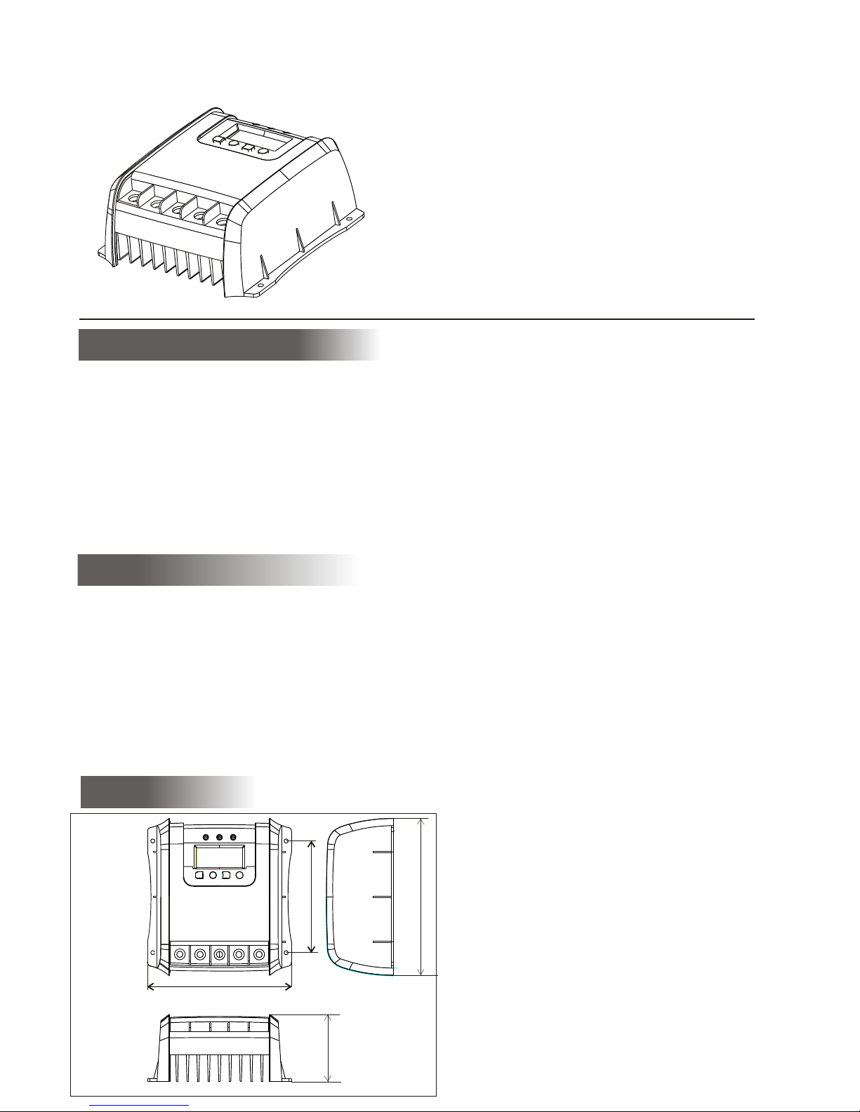
Installation
Plea se i ns talle d in t he r oom, avoi di ng direct -c learanc e,
do not i ns ta ll in the w et e nv ironmen t, w hen use it ou td oor,
plea se i ns tall co nt ro ller and ba tt eries in th e sa me place,
and th e ba tt eries i ns ta lled in the s am e place, th e co ntrolle r
can me as ur ing the b at te ry temper at ure, char ge
volt ag e re gulat io n.
Attention:
1. Scr ew s sp ecifi ca ti ons M3 × 10
2. Mak e su re h eat-l oc at ion were no t l bl ocke
6.3 / 1 6 0
4. 9 / 124
6. 8 / 174
3.0 / 7 5
inc h / m m
Uni t :
Page 2
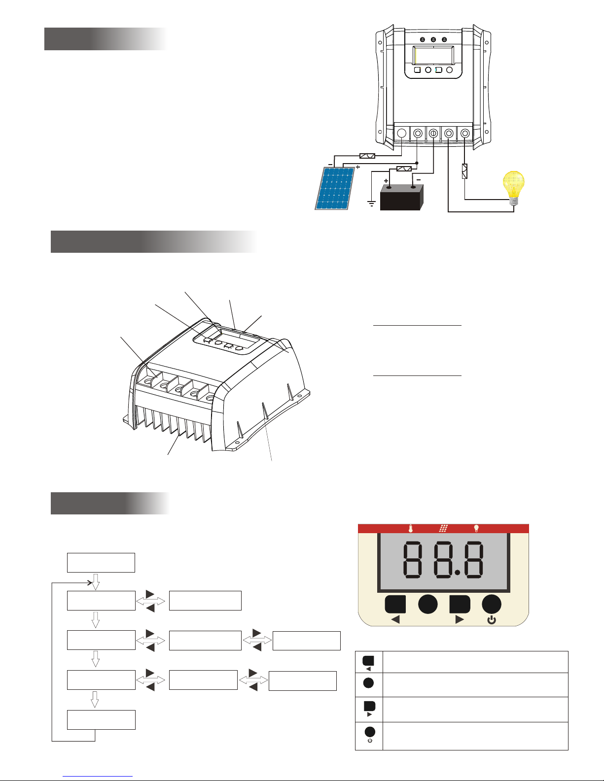
Part Names
Operating
Radia tor
Termina l Blo cks
Button
LCD
shell
Tempera tur e sensor
Charge ind icator
load in dic ator
charge indicator (green LED)
ON: ch arg ing
OFF: no chargi ng
ON: St op ou tput
OFF: Output no rma l
SE T
Parameter Browse
SE T
SE T
Ambi ent
temp era ture
SE T
Char gin g curre nt
Char ge ca pacit y
Load c urr ent Load v olt age
capacity percent
start
Key Descri ption
SET
Previous
Func tio n key, cycle d isp lay mai n men u
Load ON/OF F
Connecting
1. Con ne ct s equence 1 . --2. --3.
2. Wie r si ze : 50A: Min1 0m m
60A: Min 12 mm
3. Gro un di ng the sola r sy stem: Be aw ar e that the po si ti ve term in al s
of the S NC c on troller a re c onnecte d in ternall y an d th erefo re h av e
the sa me e le ctrical p ot ential. i f an y groundi ng i s re quire d ,a lw ays
do thi s on t he p ositive w ir es.
load s batt ey sola r ar ra y
2
charge indicator (Red LED)
PV votage
Batt ery v otage
Load s tat e
Back
Ba t t e ry
Fu s e
Fu s e
Fu s e
REMA RK : Mi nd the re co mm endatio ns o f your batt er y
manu fa ct urer, we s tr on gly recom me nd connec ti ng a fuse
dire ct ly t o the bat te ry t o protect a ny s hort circ ui t at t he batt er y
wiri ng . Th e fu se must tak e th e ch arge co nt ro ller nomi na l current :
SNC5 0 : 10 0A
SNC6 0: 1 20 A
Page 3

setting
start
SE T
The co ntroller user can m odify:
1. B oo st voltag e 2. Load l ow-voltage prot ection point
3. Tempe rature units. 4. Charging c apacity cleared
SE T
SE T
Short push
Charging c apacity cleared
SE T
(twinkle )
temperat ure units
SE T
Technical Date
MODEL SNC50 SNC60
Max.solar panel current 50 A 6 0 A
Max. load current 50A 60A
Use voltage 12V/24V,auto m a t i c r e c o g n i t i o n
NO-load current 10 mA
Overvoltage protection 1 5 . 5 V / ( 1 2 V s y s t e m ), 3 1 V / ( 2 4 V s y s t e m )
Work temperature range: -35℃- - + 5 5℃
Boost voltage 14.6V(12V sy s t e m ) , 2 9 . 2 V / ( 2 4 V s y s t e m ) ( T h e d e f a u l t v a l u e , i t c a n b e s e t )
Equalization voltage 14. 8 V ( 1 2 V s y s t e m ) , 2 9 . 6 / ( 2 4 V s y s t e m )
Float voltage 13.8V(12V sy s t e m ) , 2 7 . 6 V / ( 2 4 V s y s t e m )
Recharge voltage 13.2V(1 2 V s y s t e m ); 2 6 . 4 / ( 2 4 V s y s t e m );
Temperature compensati o n - 5 m v /℃/ 2 V
Low-voltage disconnect 1 1 V ( 1 2 V s y s t e m ); 2 2 V / ( 2 4 V s y s t e m ); ( T h e d e f a u l t v a l u e , i t c a n b e s e t ) )
Load reconnect voltage 12. 6 V(1 2 V s y s t e m ) , 2 5 . 2 V /(2 4 V s y s t e m) ;
Charge control mode PWM
diplay mode LCD
When you are m ake setting opera tion, the related n umb er will twinkl e.
After you fi nish the setting, t he tw inkle will sto p and t he related number
will save.
hold 5 secon ds
boost volt age
( )twinkle
load lo w-vol tag e
protecti on point
(twinkle )
Short push
charging c apacity
(twinkle )
Short push
Reduce
( reduce 0.0 1V)
the voltag e value
increase t he voltage value
( increase 0 .01V)
Reduce
( reduce 0.0 1V)
the voltag e value
increase t he voltage value
( increase 0 .01V)
Fahrenhe it and Celsius cycl e show
 Loading...