

Page 1

Description of Functions
1.
(mic roprocess or) by 10 % to 30 % ( effi ciency > 95 % )
2. Swi tchable cha racteri st ic lines of c harging for o ptimum ch ar ging of Gel /dryfit /A GM/flee ce or acid/ le ad-acid , as well
as LiF ePO4 batter ies .
3. Two Batter y Chargin g Po rts: Autom atic char gi ng of the mai n battery or bo ard batte ry ( Board I):
Supp ort chargin g and trick le c harging ( max. 1 A) of the v eh icle's st arter bat te ry (Start I I) w ith overc harge pro te ction
4. Una ttended Cha rging: St an dard prot ection ag ai nst overl oad, overhe ating, re verse batte ry and back d is charge of t he
batt ery (in case of i nsufficient s olar powe r, su ch as at twil ight, at ni gh t etc.).
5. Ove rcharge pro tection : Re duction o f the charg in g current o f the battery i n case of exc es sive sola r power and f ul l
batt ery. Im mediate r ec harging i n case of pow er c onsumpt ion to ensu re a lways the b est possibl e chargin g state of the
batt ery.
6. Con nection for t emperat ur e sensor, Aut omatic ad ap tation of t he chargi ng v oltage to t he battery te mperatu re . In case
of low o utside temp erature s, f ull
char ging of the wea ker batte ry i s improve d, and in cas e of s ummery te mperature s unneces sary batter y gassing w il l
be avo ided.
This i s highly reco mmended , if t he batter y is exposed to s trong var ia tions in te mperatu re , such as in th e mo tor
comp artment.
Incr eased MPP charg in g current c ompared w it h convent ional con tr ollers, d ue to ultramo dern cont roller tech nology
User Manual
MPPT5012A-DUO|MPPT5025A-DUO
Thank you v ery much for b uying our pr oduct ,Ple ase read
thoroug hly before u sing the pro uuct
solar controllerDual battery
MPPT
Safety Regulations and Appropriate Application:
1.Ch arging of lea d-gel, le ad-AGM, lea d-acid or L iF ePO4 (wit h integra te d BMS!) bat teries of the i ndicate d no minal vol tage
and si multaneou s supply of t he c onsumer s being con ne cted to the se batter ie s in fixed in stalled sys tems.
2.So lar panels up t o the maxim um p ower rati ng (Wp) of th e us ed solar co ntrolle r.
3.The in dicated c ab le cross se ctions at the c harging p orts and at the p anel inpu t.
4.With f uses of the ind icated ca pacity near t he batter y to p rotect th e cabling b et ween batt ery and cha rg ing ports .
5.Inst allatio n in a w ell-ven tilated roo m, protec te d from rain , humidit y, dust , aggress iv e battery g as, as well as in a n
envi ronment bei ng free fro m co ndensat ion water
6.Ex cept for the fu se, the uni t is n ot equipp ed with par ts , which can b e replace d by t he user. Alwa ys use replac ement car
fuse s of the indica ted capac it y!
7.Ke ep children a way from th e so lar contr oller and t he b atterie s.
Page 2
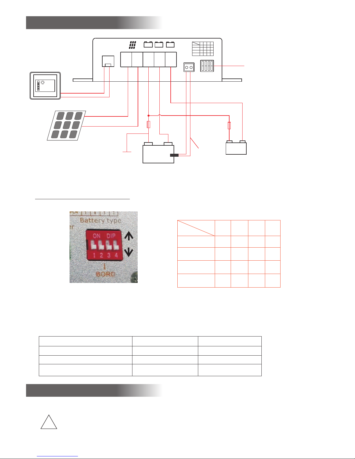
Connection Plan
+
-
-
Ⅰ
+
Ⅱ
Ⅰ
+
mainⅡSTART
+
Temp. sense r
Ⅰ
MAI N
Bat tery ty pe
Ⅰ
MAI N
1 2 3 4
GEL
Lead Acid
AGM2
LiFePO4
↑
↑↑↑
↑
↑↑↑
↑
↑↑↑
↑↑↑↑
Battery 12 V
Ⅰ
Main
Ⅱ
START
-
+
+
-
+
-
Select th e battery
type of mai b attery
(See Batt ery type tab le)
Main b attery
Temper ature
Sens or
(opt ion)
Battery selection
Battery type
1 2 3 4
GEL
Lead Acid
AGM2
LiFePO4
↑
↑↑↑
↑
↑↑↑
↑
↑↑↑
↑↑
↑
↑
Total capac ity of pane l
MPPT 5012A-DUO m ax.165W
MPPT 5025A-DUO m ax. 350W
NOTE:
Inst all the solar c ontroll er n ear
the ma in battery
Fuse
Vehic le
chas sis
main b attery
moto r battery
(opt ion)
Fuse
5A
Note:
The co nnection pl an shows th e ma ximum ter minal ass ig nment for o peratio n of a ll existi ng function s of the sola r
cont roller. The mini mum termina l assignm en t consist s of the sola r pa nel input s ("+" and "- ") a nd the conn ections of
the ma in battery.
Alwa ys connect th e fuses as cl os e as possib le to the bat te ries (cab le protec ti on!).
Requ ired Cable Cr oss Secti ons, MPPT 50 12A-DUO M PPT5024A- DUO
+/- Pa nel cables, l ength as re qu ired 2.5- 4 mm 2 6-10 mm 2
+/- Ba ttery I cable s, length m ax . 2 m 2.5-4 mm 2 6- 10 m m 2
Fuse c lose to batte ry I 15 A 30 A
Note s
Connection
*The p olarities ( + a nd - ) of solar p an el and batt eries are a bs olutely t o be observ ed !
Obse rve the cross -sectio ns a nd length m easures o f th e cables!
!
*Con nection of th e solar con tr oller to th e battery " Bo ard I" shou ld be effected fi rst. Cable
Prot ec tion:
the fu se s near the ba tteries i nt o the + cable s (protec ti on agains t cable fire) !
*The s olar panels s hould be pr otected fro m direct su nl ight (by co vering or s ha ding) pri or to conne ct ion.
13 .3 V
LCD Me ter
(opti on)
Page 3

1.) Main B attery “M AI N I” (must be co nnected):
○Conn ect the batte ry connec ti ons of the co ntrolle r - (M inus) and + ( Plus) to the 12 V m ain batte ry, obs erving th e co rrect
pola rity and the cr oss secti on o f the cable s (refer to c on nection p lan).
○Neve r operate the c ontroll er w ithout th e battery “ Ma in I” . If the ba ttery is not co nnected , th e unit will n ot delive r a
defi ned output vo ltage.
○In cas e of wrong pola rity of bat te ry I, the int ernal saf et y fuse will b e released. The repla cement fuse s hould hav e th e same
capa city, and it shoul d be of the same ty pe (car fus e) !
Para llel chargi ng of two or se ve ral batte ries of the s am e voltage ( 12 V) is admiss ible. The batte ries are to b e “p arallel ed”
2.) Sola r Panel (mu st b e connect ed ):
Shad e th e panels to m inimize s pa rking dur ing conne ct ion and to av oid damag es d ue to event ual wrong p ol arity.
Obse rv e the cable c ross-se ct ions (ref er to conne ct ion plan) !
If sev er al small so lar panel s ar e used, the y are conne ct ed in paral lel (refe r to c onnecti on plan). Par tial shad in g of the pane ls
resu lt s in averag e higher ca pa city (see c onnecti on p lan).
3.) Star ter Batte ry „ START II“ (Optio n, can be con ne cted):
Conn ect the secon d chargin g po rt to the sec ond batte ry u sing the re d connectio n cable (wi re cross sect ion 1.5 - 2.5 m m² ).
This cable m ay be longe r. In c ase of non- utiliza ti on, this te rminal is l ef t free.
If use d, t he output f or starte r ba ttery II wi ll be working w ith reduc ed voltage an d chargin g cu rrent rat es. Th us, the val uable
sola r power will be s upplied t o bo ard/sol ar batter y I be ing more su itable.
Howe ver, the vehic les start er b attery II w ill be kept i n a co ndition , that starti ng will alw ays be possib le, even in c as e of
long er downtime s and durin g wi nter oper ation.
Conn ection of the n egative p ol e „START II“ is n ot requir ed , if the nega tive pole „ BO ARD I“ is con nected to the
vehi cle body. Depend in g on the leng th of the cab le , it may also b e connect ed t o the commo n negative
conn ection of the s olar cont ro ller or to th e negativ e po le of „BOAR D I“.
4.) Tempera tu re Sensor ( Option, can b e connect ed ):
For au tomatic ada ptation a nd c orrecti on of the cha rg ing volta ge to the bat te ry temper ature (temp erature c om pensati on).
Moun ting:
The th ermal conta ct of senso r an d battery " Main I" (in si de temper ature) shou ld be well. Thus, i t should be s cr ewed down
to the n egative pol e or positi ve p ole of the ba ttery. It is also po ssible to f as ten it at the s idewall cen tre of the ba tt ery casin g.
Ensu re that the ins tallati on p lace is not i nfluenc ed b y any sourc e of heat (mo to r block, ex haust, heat er etc.).
Conn ection:
Conn ect the tempe rature se ns or to the ter minal by me an s of a 2-pole c able (cab le c ross sect ion 0.5 - 1.5 mm² ). The p olarity
and ca ble length is o f no import ance. The solar c on troller r ecogniz es t he sensor a utomati ca lly.
Effect:
The te mperature -depend ent chargin g voltage o f ba ttery I wil l be adapte d au tomatic ally to the bat tery temp er ature.
The te mperature s ensor mea su res the bat tery temp er ature. In c ase of low temp erature s (winter ope ration) , th e chargin g
volt age will be inc reased in o rder to impro ve and acce le rate full c harging o f th e weak batt ery.
Safe ty Mode:
Batt ery Protect ion:
In cas e of too low batt ery tempe ra tures ( -30 ° C for lead ba tt eries or -2 0 °C for LiFePO 4) or too hig h ba ttery tem peratur es
(fro m +50 °C), the ch arging vo lt age will be r educed st ro ngly to saf ety charg in g voltage f or battery pr otectio n (d ependin g on
the ty pe from 12.75 V t o 13.00 V). S af ety mode, L ED "charg e" i s flashin g, but any char ging data b eing record ed hither to w ill
be kep t in memory.
Batt ery chargin g is then int er rupted, b ut the supp ly o f eventua lly conne ct ed consum ers will be con tinued by t he solar
cont roller, and th e battery i s al lowed to co ol down. As so on a s the batte ry temper at ure reach es the admiss ible rang e again,
auto matic charg ing will be c ontinued.
The so lar control ler recog nizes autom aticall y a mi ssing sen sor, cable b re ak or short -circui t of t he sensor l ines, as
well a s unreasona ble measu ring values . In that cas e, i t will swit ch automa ti cally to th e usual cha rg ing volta ge
rate s of 20 °C / 25 °C bein g recomme nd ed by the bat tery manu fa cturers .
5)
The LC D display ind icates th e fo llowing v alues: Ba tt ery volta ge, charg in g current , chargin g
capa city, stored cap ac ity and ene rgy (V, A, W, Ah, Wh )
5) LCD me ter ( Optio n, c an be conne ct ed):
Page 4

Pilot Lamps
“Batt . Full” (Batt ery fully c ha rged, gre en):
If it is l ighting: Ba ttery (ba tt eries) ha s (have) been c harged to 1 00 % , finishe d.
If it is l ighting dim ly: Main ch ar ging proc ess is stil l effe cted in the cha rging Con stant volta ge
Off: Main ch arging proc ess is stil l effe cted in the c ha rging con stant cur re nt
“>80 % ” (green):
If it is l ighting: Ba ttery has b ee n charged a lmost fully. Sol ar c ontroll er is still i n th e chargin g constan t cu rrent
"Cha rge" (only MP PT5012A -D UO, green ):
If it is l ighting: The br ig htness fr om slight dim ly lighti ng up to full bri ghtness i nd icates th e chargin g cu rrent int ensity.
Off: Solar p ower is insuffi ci ent.
If it is f lashing: Ba ttery Prote ction:
1. Switc hover to sa fe ty chargi ng voltag e in c ase of batt ery overtem peratur e, s uch as > +50° C,
automa tic retur n an d continu ed chargi ng i n case of dro p of the batter y tempera tu re by 2°C.
2. Disco nnectio n, c aused by ov ervolta ge a t the batte ry.
“MPP ” at MPPT5012 A-DUO (co nt rol, gree n):
If it is l ighting: Pr oper func ti oning of th e solar contr oller.
Shor t flashing: D isplay of r ea diness fo r service in ca se of missi ng solar powe r (at night ).
“MPP ’ at MPPT5025A -DUO(co nt rol, gree n):
If it is l ighting: Pr oper func ti oning of th e solar contr oller. The brigh tness fro m sl ight diml y lightin g up t o full
bright ness indi ca tes the cha rging cur re nt intens ity.
If it is f lashing: Ba ttery Prote ction:
1. Switc hover to sa fe ty chargi ng voltag e in c ase of batt ery overtem peratur e, s uch as > +50 °C ,
automa tic retur n an d continu ed chargi ng i n case of dro p of the batter y tempera tu re by 2 °C.
2. Disco nnectio n, c aused by ov ervolta ge a t the batte ry.
Shor t flashing: D isplay of r ea diness fo r service in ca se of missi ng solar powe r (at night ).
“Bat t. Low“ (yell ow):
If it is l ighting: Lo w voltage a t ma in batter y I.
The ba ttery shoul d be rechar ge d as soon as po ssible!
All pi lot lamps (5) a re flashi ng :
The po sitions of th e selecto r sw itches "M AIN Batte ry " are incor rect. For rea sons of saf et y, th e solar con tr oller is sw itched-
off. Adju st t he desire d battery typ e accordi ng t o table 1.
Operating Instructions:
Lifetime of the battery:
Rech arge totall y dischar ge d batteri es immedi at ely!
Sulp hation of the l ead batte ry p lates due t o total dis ch arge is to be p revented by s oon charg ing, partic ularly in c as e
of hig h ambient tem peratur es . If the grad e of sulpha ti on is not too i ntensive, t he batter y ca n recover p art of the
batt er y capacit y after sev er al chargi ng/disc ha rging cyc les.
Page 5

Keep b atteries co ol and dry; c ho ose an appr opriate l oc ation for i nstalla ti on.
In cas e of insufficie nt solar powe r and/or hi gh c urrent co nsumpti on , the batte ry should be su bject to oc casional
full c harging by me ans of a main s su pply char ger.
The 12 V solar c ontroll er s protect t hemselv es a gainst co nnectio n of e xcessiv e battery vol tage rate s or w ill be swit ched-
off in case of d efectiv e ad ditiona l chargin g sy stems, sw itching t hr eshold 15 .0-16.0 V.
Over voltage Lim itation :
Sens itive consu mers are pr ot ected by me ans of a limi ta tion of the c harging vol tage to max . 15.0 V during a ll modes of
char ging.
Over load / Overhe ating Pro te ction Sol ar Controll er:
The solar co ntrolle r is equipped w ith a doubl e el ectroni c protect io n against o verload a nd w ith an auto matic pro te ction
agai nst adverse i nstalla ti on condit ions (e. g. i ns ufficient v en tilatio n, excessiv e ambient t emperatur es) by grad ua l
redu ction of the ch arging ca pa city.
Voltage Mea suremen t: M easurem ent of the vo lt age is to be effe ct ed at the bat tery and neve r at the sola r co ntrolle r
(los s at the chargi ng cable) .
Over voltage Pro tection :
Battery charging parameter
Batt ery type
GEL
Lead Ai cd/AGM1
AGM2
LiFe PO4
Boos t charging vo ltage
14.3 V (3-10h)
14.4 V (1.5-6h)
14.7 V (1.5-5h)
14.6 V (0.5-3h)
Floa t charging vo ltage
13.8 V
13.4 5V
13.5 V
13.6 V
Defa ult tempera ture
20℃
20℃
20℃
20℃
ATTENTION: Only connect LiFePO4 batteries with integrated BMS!
Note : The po ssible pa rallel/fl oating op er ation wit h consume rs b eing conn ected to th e
batt ery is also aut omatica ll y conside red by all ch ar ging prog rams.
Part ially Disch arged Bat te ries:
In con tr ast to othe r battery t yp es, batte ries on lea d ba sis do not ha ve any harmfu l memory effect . Consequ en tly: In
case o f doubt, part ially dis ch arged bat teries ha ve t o be charge d fully as so on a s possibl e.
Alway s store only fu lly charg ed l ead batte ries. Rec ha rge them pe riodica ll y, pa rticula rl y in case of us ed (older)
batt eries and hig her tempe ra tures.
Charging Process
V/I
Char ging time
char ging voltag e (V)
char ging curren t(I)
Floa t charging vo ltage
Boos t charging vo ltage
<100 %
<75%
100% m aintenanc e
Page 6

Technical Data:
MPPT50 12 A-DUO MPP T5 025A-DU O
Capa city of Solar M odule (re co mmended / m ax.): 50 - 16 5 Wp 5 0 - 350 Wp
Curr ent Solar Mod ule: 0 - 10 A 0 - 21.0 A
Volta ge Solar Modu le (Voc): max. 5 0 V ma x. 50 V
Nomi nal Voltag es o f Batteri es MainI and St art II: 12 V 12 V
Char ging Curren t: 0 - 12 A 0 - 25.5 A
Curr ent Consump tion Stan d- by (max.) : 4 mA 4 mA
Main P ort Battery I :
Char ging/Floa ting/Lo ad Current: 0 - 1 2 A 0 - 25.5 A
Max. P relim. Char g. Curren t
(tot ally discha rged batt er y): 6 A (<8 V) 12,7 A (<8 V)
Rese t Voltage (30 se c): 12.7 V 12.7 V
Char ging Volta ge L imitati on (max.): 15 .0 V 15.0 V
Over load Protec tion (Cur re nt Limiti ng Device ): Yes Yes
Inte grated Prot ection ag ai nst Short -circui t: Yes Yes
Inte grated Prot ection ag ai nst Overt emperat ur e: Yes Yes
Inte grated Cool ing Fan wit h Temp. Co ntrol: Yes Yes
Unit F use (Type FKS) : 15 A 30 A
Inpu t for Battery I Tempe ra ture Sens or: Yes Yes
Char ging Timer: 3- fo ld 4-fold
Auxi liary Port Veh icle Star te r Battery I I (Start II ):
Char ging Curren t: 0 - 1.0 A 0 - 1.0 A
Over load Protec tion (Cur re nt Limiti ng Device ): Yes Yes
Inte grated Prot ection ag ai nst Short -circui t: Yes Yes s
Inte grated Prot ection ag ai nst Overt emperat ur e: Yes Yes
Dime nsions, inc l. Mounti ng Flanges (m m): 147x7 4x 40mm 147x 74 x40mm
Weight : 340g 4 00 g
Ambi ent Conditi ons, Humi dity of Air: max . 95 % RH, no conde nsation
Ava ilable Accessor ie s:
Temper ature Senso r
SH E NZ H EN O LYS C OMPA NY L I MI T ED
Addr : 5 floor, B build ing of Shen g De Industri al Park, La ng K ou, Da Lang ,
Long H ua New distri ct, Shenz hen, Guangd ong, Chin a
TEL: + 86 0755 29533 796
E-ma il: olys@ol ys-digi ta l.com
www.o lyssolar.c om
MADE I N CHINA
LCD me ter
 Loading...