

Olympus Panametrics Epoch 4 Plus User Manual

EPOCH 4PLUS
Advanced Test Equipment Rentals
www.atecorp.com 800-404-ATEC (2832)
®
E
s
t
a
b
l
i
s
h
e
d
1
9
8
1
Part No. 910-250C
USER’S MANUAL

In accordance with European Directive 2002/96/EC on Waste Electrical and Electronic Equipment, this symbol
indicates that the product must not be d isposed o f as unsorted municipal was te, but sh ould be collected separately.
Refer to your local Olympus distributor for return and/or collection systems avai labl e in your country.
Copyright 2005 by Olympus NDT, Inc. All rights reserved.
No part of this manual may be reproduced or transm itte d in any form or by any means , el ectroni c
or mechanical, including photocopying, recording, or by any information storage and retrieval
system, without the written permission of Olympus NDT, except where permitted by law. For
information, contact: pana@OlympusNDT.com.
Other product names mentioned in this document may be trademarks of their respective companies, and
are mentioned for identification purposes only.
Printed in the United States of America.

Warranty
Warranty
The EPOCH 4PLUS Digital Ultrasonic Fl aw Detector has been design ed and
manufactured as a high quality instrument .
Inspect the unit thoroughly upon receipt for evidence of external or internal damage that
may have occurred during shipment. Notify the carrier making the delivery immediately
of any damage, since the carrier is normally liable for damage in shipment. Preserve
packing materials, waybills, and other shipping documentation in order to establish
TM
NDT
damage claims. After notifying the carrier, contact Olympus
so that we may assist
in the damage claims, and provide replacement equipment, if necessary.
Olympus
NDT guarantees the EPOCH 4PLUS to be free from defects in materials and
workmanship for a period of one year (t welve months ) from date of shipment. This
warranty only covers equipment that has been used in a proper manner as described in this
instruction ma nual and has not been subjec ted to excessive abuse, at tempted unauthorized
repair, or modificatio n. DURING THIS WARRANTY PERIOD, Olymp us
NDT
LIABILITY IS STRICTLY LIMITED TO REPAI R OR REPLACEMENT OF A
DEFECTIVE UNIT AT ITS OPTION. Olympu s
NDT does not warrant the EPOCH
4PLUS to be suitable of intended use, or fitness for any particular application or purpose.
Olympus
NDT accepts no liab ility for consequent ial or inci dental damag es includi ng
damage to property and/or personal injury. In addition to our standard one year warranty,
Olympus
NDT also offers an optional two year warranty (call for further details).
This warranty do es not include transducers, transducer cables, or battery. The customer
will pay shipping ex pense to the Olympus
NDT plant for warranty repair; Olympus NDT
will pay for the return of the repaired equipment. (For instruments not under warranty, the
customer will pa y shipping ex penses both ways.)
In this manual, we hav e attempted to teach the prope r operation o f the EPOCH 4PLUS
consistent wit h accepted flaw detectio n technique s. We believe t he procedures and
examples give n are accura te. However, t he informat ion contain ed herein is intended
solely as a teaching aid and should not be used in any particular application without
independent testing and/or verification by the operator or the supervisor. Such
independent verification of procedures become more important as the criticality of the
application increases.
For these reasons, we make no warranty, expressed or implied, that the techniques,
examples, or pr ocedures de scribed her ein are con sistent with industry st andards n or that
they will meet the requirements of any particular application. Olympus
NDT expressly
disclaims all implied warranties of merchantability and of fitness for any particular
application.
Part # 910-250C
Olympus
responsibility for modifying previously manufactured products. Olympus
NDT reserves the right to modify all products without incurring the
NDT does not
assume any liability for the results of particular installations, as these circumstances are
not within our control.
THE WARRANTIES SET FORTH HEREIN ARE EXCLUSI VE AND ARE IN LIEU
OF ALL OTHER WARRANTIES WHETHER STATUTORY, EXP RESS, OR
IMPLIED (INCLUDING WARRANTIES OF MERCHANTABI LITY AND FITNESS
FOR A PARTICULAR PURPOSE, AND WARRANTIES ARISING FR OM COURSE
OF DEALING OR USAGE OR TRADE).

EPOCH 4PLUS

Table of Contents
Table of Contents
Warranty
Table of Contents
1 Preface . . . . . . . . . . . . . . . . . . . . . . . . . . . . . . . . . . . . . . . . . . . . . . . . . . . . . . . 1
1.1 Product Description . . . . . . . . . . . . . . . . . . . . . . . . . . . . . . . . . . . . . . . . . . . . . . . . 1
1.2 About this Document . . . . . . . . . . . . . . . . . . . . . . . . . . . . . . . . . . . . . . . . . . . . . . . 2
1.3 Audience. . . . . . . . . . . . . . . . . . . . . . . . . . . . . . . . . . . . . . . . . . . . . . . . . . . . . . . . . 2
1.4 Typographic Conventions . . . . . . . . . . . . . . . . . . . . . . . . . . . . . . . . . . . . . . . . . . . 3
1.5 If You have Documentation Comments. . . . . . . . . . . . . . . . . . . . . . . . . . . . . . . . . 4
1.6 Revision History. . . . . . . . . . . . . . . . . . . . . . . . . . . . . . . . . . . . . . . . . . . . . . . . . . . 4
1.7 Technical Help . . . . . . . . . . . . . . . . . . . . . . . . . . . . . . . . . . . . . . . . . . . . . . . . . . . . 4
2 Operating the Power Supply. . . . . . . . . . . . . . . . . . . . . . . . . . . . . . . . . . . . . . 5
2.1 Using AC Line Power . . . . . . . . . . . . . . . . . . . . . . . . . . . . . . . . . . . . . . . . . . . . . . 5
2.2 Using Battery Power . . . . . . . . . . . . . . . . . . . . . . . . . . . . . . . . . . . . . . . . . . . . . . . 5
2.3 Operating Time for the Battery . . . . . . . . . . . . . . . . . . . . . . . . . . . . . . . . . . . . . . . 6
2.4 Replacing the Battery. . . . . . . . . . . . . . . . . . . . . . . . . . . . . . . . . . . . . . . . . . . . . . . 6
2.5 Charging the Battery . . . . . . . . . . . . . . . . . . . . . . . . . . . . . . . . . . . . . . . . . . . . . . . 6
2.6 Using a “AA” Alkaline Battery . . . . . . . . . . . . . . . . . . . . . . . . . . . . . . . . . . . . . . . 7
3 Managing Basic Operations . . . . . . . . . . . . . . . . . . . . . . . . . . . . . . . . . . . . . . 9
3.1 Powering-up/LCD Screen Adjustment. . . . . . . . . . . . . . . . . . . . . . . . . . . . . . . . . . 9
3.2 Using the Keypad. . . . . . . . . . . . . . . . . . . . . . . . . . . . . . . . . . . . . . . . . . . . . . . . . 10
3.2.1 Enter Key . . . . . . . . . . . . . . . . . . . . . . . . . . . . . . . . . . . . . . . . . . . . . . . . 10
3.2.2 Direct Access Operation . . . . . . . . . . . . . . . . . . . . . . . . . . . . . . . . . . . . 10
3.3 Summarizing Keypad Functions . . . . . . . . . . . . . . . . . . . . . . . . . . . . . . . . . . . . . 10
3.3.1 Main Keypad Functions. . . . . . . . . . . . . . . . . . . . . . . . . . . . . . . . . . . . . 12
3.3.2 Datalogger Keypad Functions . . . . . . . . . . . . . . . . . . . . . . . . . . . . . . . . 15
3.4 Editable Parameters Software . . . . . . . . . . . . . . . . . . . . . . . . . . . . . . . . . . . . . . . 17
3.5 Color Settings. . . . . . . . . . . . . . . . . . . . . . . . . . . . . . . . . . . . . . . . . . . . . . . . . . . . 20
3.6 Managing the Display . . . . . . . . . . . . . . . . . . . . . . . . . . . . . . . . . . . . . . . . . . . . . 20
3.6.1 Full Screen A-Scan Display. . . . . . . . . . . . . . . . . . . . . . . . . . . . . . . . . . 20
3.6.2 Split Screen Display. . . . . . . . . . . . . . . . . . . . . . . . . . . . . . . . . . . . . . . . 21
3.6.3 Display Flags and Markers. . . . . . . . . . . . . . . . . . . . . . . . . . . . . . . . . . . 22
3.7 Setting-up Parameters. . . . . . . . . . . . . . . . . . . . . . . . . . . . . . . . . . . . . . . . . . . . . . 23
3.7.1 Language Selection. . . . . . . . . . . . . . . . . . . . . . . . . . . . . . . . . . . . . . . . 24
3.7.2 Units of Measurement . . . . . . . . . . . . . . . . . . . . . . . . . . . . . . . . . . . . . . 25
3.7.3 Analog Out. . . . . . . . . . . . . . . . . . . . . . . . . . . . . . . . . . . . . . . . . . . . . . . 25
3.7.4 Clock . . . . . . . . . . . . . . . . . . . . . . . . . . . . . . . . . . . . . . . . . . . . . . . . . . . 25
3.7.5 Advanced User. . . . . . . . . . . . . . . . . . . . . . . . . . . . . . . . . . . . . . . . . . . . 26
3.7.6 USB Connector . . . . . . . . . . . . . . . . . . . . . . . . . . . . . . . . . . . . . . . . . . . 27
Part # 910-250C

EPOCH 4Plus
3.7.7 VGA Output On/Off . . . . . . . . . . . . . . . . . . . . . . . . . . . . . . . . . . . . . . . 28
3.7.8 Beep On . . . . . . . . . . . . . . . . . . . . . . . . . . . . . . . . . . . . . . . . . . . . . . . . . 28
3.7.9 Grid On/Off . . . . . . . . . . . . . . . . . . . . . . . . . . . . . . . . . . . . . . . . . . . . . . 28
3.7.10 Keypad Lock Functions . . . . . . . . . . . . . . . . . . . . . . . . . . . . . . . . . . . . . 28
3.7.11 Filled Live . . . . . . . . . . . . . . . . . . . . . . . . . . . . . . . . . . . . . . . . . . . . . . . 29
3.7.12 Filled Peak . . . . . . . . . . . . . . . . . . . . . . . . . . . . . . . . . . . . . . . . . . . . . . . 29
3.7.13 “AA” Alkaline Battery Selection. . . . . . . . . . . . . . . . . . . . . . . . . . . . . . 29
4 Adjusting the Pulser Receiver . . . . . . . . . . . . . . . . . . . . . . . . . . . . . . . . . . . 31
4.1 Adjusting System Sensitivity. . . . . . . . . . . . . . . . . . . . . . . . . . . . . . . . . . . . . . . . 31
4.2 Using AUTO-80%. . . . . . . . . . . . . . . . . . . . . . . . . . . . . . . . . . . . . . . . . . . . . . . . 31
4.3 Setting a Gain Reference Level and Adding Scanning Gain . . . . . . . . . . . . . . . . 33
4.4 Using the Pulser Key . . . . . . . . . . . . . . . . . . . . . . . . . . . . . . . . . . . . . . . . . . . . . . 34
4.4.1 Waveform Rectification. . . . . . . . . . . . . . . . . . . . . . . . . . . . . . . . . . . . . 34
4.4.2 Pulser Energy . . . . . . . . . . . . . . . . . . . . . . . . . . . . . . . . . . . . . . . . . . . . . 35
4.4.3 Damping. . . . . . . . . . . . . . . . . . . . . . . . . . . . . . . . . . . . . . . . . . . . . . . . . 35
4.4.4 Test Mode. . . . . . . . . . . . . . . . . . . . . . . . . . . . . . . . . . . . . . . . . . . . . . . . 36
4.4.5 Narrowband Filters. . . . . . . . . . . . . . . . . . . . . . . . . . . . . . . . . . . . . . . . . 36
4.4.6 Pulser Type Selection. . . . . . . . . . . . . . . . . . . . . . . . . . . . . . . . . . . . . . . 38
4.4.7 Pulser Frequency Selection . . . . . . . . . . . . . . . . . . . . . . . . . . . . . . . . . . 39
5 Managing Special Waveform Functions . . . . . . . . . . . . . . . . . . . . . . . . . . . 41
5.1 Reject . . . . . . . . . . . . . . . . . . . . . . . . . . . . . . . . . . . . . . . . . . . . . . . . . . . . . . . . . . 41
5.2 Peak Memory . . . . . . . . . . . . . . . . . . . . . . . . . . . . . . . . . . . . . . . . . . . . . . . . . . . . 41
5.3 Peak Hold. . . . . . . . . . . . . . . . . . . . . . . . . . . . . . . . . . . . . . . . . . . . . . . . . . . . . . . 42
5.4 Screen Freeze . . . . . . . . . . . . . . . . . . . . . . . . . . . . . . . . . . . . . . . . . . . . . . . . . . . . 42
6 Using the Gates . . . . . . . . . . . . . . . . . . . . . . . . . . . . . . . . . . . . . . . . . . . . . . . 45
6.1 Positioning Gate 1 . . . . . . . . . . . . . . . . . . . . . . . . . . . . . . . . . . . . . . . . . . . . . . . . 45
6.2 Positioning Gate 2 . . . . . . . . . . . . . . . . . . . . . . . . . . . . . . . . . . . . . . . . . . . . . . . . 45
6.3 Taking Thickness Readings . . . . . . . . . . . . . . . . . . . . . . . . . . . . . . . . . . . . . . . . . 46
6.4 Taking Echo-to-Echo Thickness Readings . . . . . . . . . . . . . . . . . . . . . . . . . . . . . 47
6.5 Locating Flaws with an Angle Beam Transducer . . . . . . . . . . . . . . . . . . . . . . . . 48
6.6 Measuring Signal Amplitude . . . . . . . . . . . . . . . . . . . . . . . . . . . . . . . . . . . . . . . . 49
6.7 Operating Time-of-Flight (TOF) Mode . . . . . . . . . . . . . . . . . . . . . . . . . . . . . . . . 50
6.8 Using the Zoom Feature. . . . . . . . . . . . . . . . . . . . . . . . . . . . . . . . . . . . . . . . . . . . 51
6.9 Activating Gate Alarms . . . . . . . . . . . . . . . . . . . . . . . . . . . . . . . . . . . . . . . . . . . . 52
6.9.1 Threshold Alarms. . . . . . . . . . . . . . . . . . . . . . . . . . . . . . . . . . . . . . . . . . 52
6.9.2 Minimum Depth Alarm . . . . . . . . . . . . . . . . . . . . . . . . . . . . . . . . . . . . . 53
6.9.3 Minimum Depth Alarm with a Single Gate. . . . . . . . . . . . . . . . . . . . . . 53
6.9.4 Minimum Depth Alarm in the Echo-to-Echo Measurement Mode . . . . 54
6.9.5 Alarm Condition Storage . . . . . . . . . . . . . . . . . . . . . . . . . . . . . . . . . . . . 54

Table of Contents
7 Calibrating the EPOCH 4PLUS . . . . . . . . . . . . . . . . . . . . . . . . . . . . . . . . . . . 55
7.1 Getting Started . . . . . . . . . . . . . . . . . . . . . . . . . . . . . . . . . . . . . . . . . . . . . . . . . . . 55
7.2 Calibrating with a Straight Beam Transducer . . . . . . . . . . . . . . . . . . . . . . . . . . . 56
7.3 Calibrating with a Delay Line Transducer. . . . . . . . . . . . . . . . . . . . . . . . . . . . . . 59
7.4 Calibrating with a Dual Element Transducer. . . . . . . . . . . . . . . . . . . . . . . . . . . . 61
7.5 Calibrating with an Angle Beam Transducer. . . . . . . . . . . . . . . . . . . . . . . . . . . . 64
7.5.1 Locating the Beam Index Point (B.I.P.). . . . . . . . . . . . . . . . . . . . . . . . . 65
7.5.2 Verifying the Refracted Angle (Beta) . . . . . . . . . . . . . . . . . . . . . . . . . . 66
7.5.3 Calibrating for Distance. . . . . . . . . . . . . . . . . . . . . . . . . . . . . . . . . . . . . 67
7.5.4 Calibrating for Sensitivity . . . . . . . . . . . . . . . . . . . . . . . . . . . . . . . . . . . 69
8 Managing the Datalogger and Data Communication Features . . . . . . . . . 71
8.1 Defining the Datalogger Storage Capacity. . . . . . . . . . . . . . . . . . . . . . . . . . . . . . 71
8.2 Using the Memory Screen . . . . . . . . . . . . . . . . . . . . . . . . . . . . . . . . . . . . . . . . . . 72
8.3 Using the Alphanumeric Keypad . . . . . . . . . . . . . . . . . . . . . . . . . . . . . . . . . . . . . 73
8.4 Creating Files and Identifier (ID) Codes . . . . . . . . . . . . . . . . . . . . . . . . . . . . . . . 74
8.5 Saving Waveforms and Thickness Readings . . . . . . . . . . . . . . . . . . . . . . . . . . . . 75
8.6 Incrementing ID Codes . . . . . . . . . . . . . . . . . . . . . . . . . . . . . . . . . . . . . . . . . . . . 76
8.7 Recalling Transducer Calibrations and Waveforms. . . . . . . . . . . . . . . . . . . . . . . 77
8.8 Saving and Recalling Quick Recall Calibrations. . . . . . . . . . . . . . . . . . . . . . . . . 78
8.9 Creating Memos. . . . . . . . . . . . . . . . . . . . . . . . . . . . . . . . . . . . . . . . . . . . . . . . . . 78
8.10 Editing a File . . . . . . . . . . . . . . . . . . . . . . . . . . . . . . . . . . . . . . . . . . . . . . . . . . . . 79
9 Using Software Options . . . . . . . . . . . . . . . . . . . . . . . . . . . . . . . . . . . . . . . . 83
9.1 Defining Active/Inactive Options . . . . . . . . . . . . . . . . . . . . . . . . . . . . . . . . . . . . 83
9.2 Distance Amplitude Correction (DAC) . . . . . . . . . . . . . . . . . . . . . . . . . . . . . . . . 84
9.2.1 Drawing DAC Curves . . . . . . . . . . . . . . . . . . . . . . . . . . . . . . . . . . . . . . 84
9.2.2 Special Considerations for JIS Z3060 DAC Curves . . . . . . . . . . . . . . . 86
9.2.3 Saving and Recalling DAC Curves . . . . . . . . . . . . . . . . . . . . . . . . . . . . 86
9.2.4 Setting Alarms in DAC Mode . . . . . . . . . . . . . . . . . . . . . . . . . . . . . . . . 87
9.2.5 Exiting DAC Mode . . . . . . . . . . . . . . . . . . . . . . . . . . . . . . . . . . . . . . . . 87
9.3 Time Varied Gain (TVG). . . . . . . . . . . . . . . . . . . . . . . . . . . . . . . . . . . . . . . . . . . 87
9.3.1 Activating and Calibrating TVG . . . . . . . . . . . . . . . . . . . . . . . . . . . . . . 88
9.3.2 Saving and Recalling TVG Setups. . . . . . . . . . . . . . . . . . . . . . . . . . . . . 89
9.3.3 Exiting TVG Mode . . . . . . . . . . . . . . . . . . . . . . . . . . . . . . . . . . . . . . . . 89
9.4 Advanced DAC/TVG. . . . . . . . . . . . . . . . . . . . . . . . . . . . . . . . . . . . . . . . . . . . . . 89
9.4.1 Description. . . . . . . . . . . . . . . . . . . . . . . . . . . . . . . . . . . . . . . . . . . . . . . 89
9.4.2 Option Activation and Reference Correct . . . . . . . . . . . . . . . . . . . . . . . 90
9.4.3 Gain Adjustment Options. . . . . . . . . . . . . . . . . . . . . . . . . . . . . . . . . . . . 91
9.4.4 ASME, ASME-3 and JIS Options . . . . . . . . . . . . . . . . . . . . . . . . . . . . . 92
9.4.5 20%-80% DAC Option . . . . . . . . . . . . . . . . . . . . . . . . . . . . . . . . . . . . . 94
9.4.6 Custom DAC Curves Option . . . . . . . . . . . . . . . . . . . . . . . . . . . . . . . . . 95
9.4.7 TVG Table Option . . . . . . . . . . . . . . . . . . . . . . . . . . . . . . . . . . . . . . . . . 98
9.4.8 TVG Table Setup . . . . . . . . . . . . . . . . . . . . . . . . . . . . . . . . . . . . . . . . . 100
Part # 910-250C

EPOCH 4Plus
9.4.9 Advanced DAC/TVG and the EPOCH 4PLUS Datalogger. . . . . . . . . 102
9.5 Low Pulse Repetition Frequency (LPRF) . . . . . . . . . . . . . . . . . . . . . . . . . . . . . 102
9.5.1 Activating LPRF Mode . . . . . . . . . . . . . . . . . . . . . . . . . . . . . . . . . . . . 102
9.5.2 Exiting LPRF Mode. . . . . . . . . . . . . . . . . . . . . . . . . . . . . . . . . . . . . . . 102
9.6 High Pulse Repetition Frequency (PRF) . . . . . . . . . . . . . . . . . . . . . . . . . . . . . . 103
9.6.1 Activating High PRF Mode . . . . . . . . . . . . . . . . . . . . . . . . . . . . . . . . . 103
9.6.2 Exiting High PRF Mode. . . . . . . . . . . . . . . . . . . . . . . . . . . . . . . . . . . . 103
9.7 Spotweld Overlay. . . . . . . . . . . . . . . . . . . . . . . . . . . . . . . . . . . . . . . . . . . . . . . . 103
9.7.1 Activating Spotweld Overlay Mode. . . . . . . . . . . . . . . . . . . . . . . . . . . 104
9.7.2 Defining Switchable Overlays . . . . . . . . . . . . . . . . . . . . . . . . . . . . . . . 104
9.7.3 Accessing Datalogger Storage . . . . . . . . . . . . . . . . . . . . . . . . . . . . . . . 105
9.8 Spotweld Assistant. . . . . . . . . . . . . . . . . . . . . . . . . . . . . . . . . . . . . . . . . . . . . . . 106
9.8.1 Description. . . . . . . . . . . . . . . . . . . . . . . . . . . . . . . . . . . . . . . . . . . . . . 106
9.8.2 Basic Spotweld Characteristics . . . . . . . . . . . . . . . . . . . . . . . . . . . . . . 106
9.8.3 Option Activation. . . . . . . . . . . . . . . . . . . . . . . . . . . . . . . . . . . . . . . . . 109
9.8.4 Reference Weld Setup . . . . . . . . . . . . . . . . . . . . . . . . . . . . . . . . . . . . . 110
9.8.5 Inspection Mode (Basic) . . . . . . . . . . . . . . . . . . . . . . . . . . . . . . . . . . . 112
9.8.6 Inspection Mode (Advanced). . . . . . . . . . . . . . . . . . . . . . . . . . . . . . . . 114
9.8.7 Spotweld Assistant and the EPOCH 4PLUS Datalogger. . . . . . . . . . . 117
9.9 Interface Gate . . . . . . . . . . . . . . . . . . . . . . . . . . . . . . . . . . . . . . . . . . . . . . . . . . . 121
9.9.1 Activating the Interface Gate . . . . . . . . . . . . . . . . . . . . . . . . . . . . . . . . 122
9.9.2 Operating in Standard Mode . . . . . . . . . . . . . . . . . . . . . . . . . . . . . . . . 122
9.9.3 Operating in Echo-to-Echo Mode . . . . . . . . . . . . . . . . . . . . . . . . . . . . 122
9.9.4 Managing Gate Positioning and Alarms . . . . . . . . . . . . . . . . . . . . . . . 123
9.9.5 Defining Gate Commands . . . . . . . . . . . . . . . . . . . . . . . . . . . . . . . . . . 123
9.10 Floating Gate . . . . . . . . . . . . . . . . . . . . . . . . . . . . . . . . . . . . . . . . . . . . . . . . . . . 125
9.10.1 Activating Floating Gate . . . . . . . . . . . . . . . . . . . . . . . . . . . . . . . . . . . 125
9.10.2 Operating in -6dB Mode . . . . . . . . . . . . . . . . . . . . . . . . . . . . . . . . . . . 126
9.10.3 Operating in -12db Mode. . . . . . . . . . . . . . . . . . . . . . . . . . . . . . . . . . . 127
9.10.4 Using Gate Alarms. . . . . . . . . . . . . . . . . . . . . . . . . . . . . . . . . . . . . . . . 128
9.11 Curved Surface Correction. . . . . . . . . . . . . . . . . . . . . . . . . . . . . . . . . . . . . . . . . 128
9.12 Wave Analysis . . . . . . . . . . . . . . . . . . . . . . . . . . . . . . . . . . . . . . . . . . . . . . . . . . 128
9.12.1 Activating the Wave Analysis Software:. . . . . . . . . . . . . . . . . . . . . . . 129
9.12.2 Moving the Cursors . . . . . . . . . . . . . . . . . . . . . . . . . . . . . . . . . . . . . . . 130
9.13 Onboard DGS/AVG. . . . . . . . . . . . . . . . . . . . . . . . . . . . . . . . . . . . . . . . . . . . . . 131
9.13.1 Description. . . . . . . . . . . . . . . . . . . . . . . . . . . . . . . . . . . . . . . . . . . . . . 131
9.13.2 Option Activation. . . . . . . . . . . . . . . . . . . . . . . . . . . . . . . . . . . . . . . . . 131
9.13.3 Operation . . . . . . . . . . . . . . . . . . . . . . . . . . . . . . . . . . . . . . . . . . . . . . . 137
9.13.4 DGS/AVG and the EPOCH 4PLUS Datalogger . . . . . . . . . . . . . . . . . 138
9.13.5 Relative Attenuation Measurement . . . . . . . . . . . . . . . . . . . . . . . . . . . 139
9.14 Backwall Echo Attenuator . . . . . . . . . . . . . . . . . . . . . . . . . . . . . . . . . . . . . . . . . 140
9.14.1 Description. . . . . . . . . . . . . . . . . . . . . . . . . . . . . . . . . . . . . . . . . . . . . . 140
9.14.2 Activating the Backwall Echo Attenuator . . . . . . . . . . . . . . . . . . . . . . 140
9.14.3 Operating Backwall Echo Attenuator . . . . . . . . . . . . . . . . . . . . . . . . . 141

Table of Contents
9.14.4 BEA and the EPOCH 4PLUS Datalogger . . . . . . . . . . . . . . . . . . . . . . 142
9.15 Auto-Freeze . . . . . . . . . . . . . . . . . . . . . . . . . . . . . . . . . . . . . . . . . . . . . . . . . . . . 143
9.16 AWS. . . . . . . . . . . . . . . . . . . . . . . . . . . . . . . . . . . . . . . . . . . . . . . . . . . . . . . . . . 146
9.16.1 AWS and the EPOCH 4PLUS . . . . . . . . . . . . . . . . . . . . . . . . . . . . . . . 146
9.16.2 Operating the AWS D1.1 Software . . . . . . . . . . . . . . . . . . . . . . . . . . . 146
9.16.3 Adding Scanning Gain. . . . . . . . . . . . . . . . . . . . . . . . . . . . . . . . . . . . . 148
9.16.4 Calculating A and C Values. . . . . . . . . . . . . . . . . . . . . . . . . . . . . . . . . 148
9.17 API 5UE. . . . . . . . . . . . . . . . . . . . . . . . . . . . . . . . . . . . . . . . . . . . . . . . . . . . . . . 149
9.17.1 Description. . . . . . . . . . . . . . . . . . . . . . . . . . . . . . . . . . . . . . . . . . . . . . 149
9.17.2 API 5UE and the EPOCH 4PLUS . . . . . . . . . . . . . . . . . . . . . . . . . . . . 150
9.17.3 Activating the API 5UE Software . . . . . . . . . . . . . . . . . . . . . . . . . . . . 151
9.17.4 Calibrating to a Reference Standard . . . . . . . . . . . . . . . . . . . . . . . . . . 152
9.17.5 Crack Sizing With API 5UE . . . . . . . . . . . . . . . . . . . . . . . . . . . . . . . . 156
9.17.6 API 5UE and the EPOCH 4PLUS Datalogger. . . . . . . . . . . . . . . . . . . 158
Appendix A – Specifications. . . . . . . . . . . . . . . . . . . . . . . . . . . . . . . . . . . . . . . . 159
Appendix B – Sound Velocities . . . . . . . . . . . . . . . . . . . . . . . . . . . . . . . . . . . . . 163
Appendix C – Glossary . . . . . . . . . . . . . . . . . . . . . . . . . . . . . . . . . . . . . . . . . . . . 165
Appendix D – Cable Diagrams . . . . . . . . . . . . . . . . . . . . . . . . . . . . . . . . . . . . . . 173
Appendix E – Parts List. . . . . . . . . . . . . . . . . . . . . . . . . . . . . . . . . . . . . . . . . . . . 175
Documentation Comments
Part # 910-250C

EPOCH 4Plus

1Preface
The preface provides the following introductory topics:
• Product Description
• About this Document
•Audience
• Typographi c Conven tions
• Related Documentation
• If You have Docume ntation Comments
• Revision History
• Technical Help
1.1 Product Description
Preface
The EPOCH 4PLUS is a lightweight, portable flaw detector offering ultrasonic
performance, resolution, and documentation capabilities with a color display that has
special advantages over basic, traditional displays. You can choose from eight (8) colors
for screen text, A-Scan waveform, gates, Peak Memory, DAC a nd TVG curve, and mor e.
Improvements over previous models include:
• Compatible with EMAT transducers using a frequency ra nge of 1 to 5 MHz, resolvi ng
echoes from parts as thin as 0.080 inches (2 mm) and as thick as 5 inches (125 mm).
• Capable of storing as many as 6,000 A-Scans or 120,000 thickness readings.
Calibration and test data can be labelled with a 16 character alphanumeric file name
with up to 500 files. In addition, the editing feature allows IDs to be deleted or cleared
for future use. A handy memo feature allows unlimited comment and data description
entries. A memory display screen makes it possible to review the contents of any file
by scrolling through the actual data prior to deleting or recalling the information. Any
stored data can be sent directly from the EPOCH 4PLUS to the opt ional EPOCH
4PLUS GageView PRO Interface Program, which makes it easy to save, view, send,
or move data from application to application.
Updated benefit s of the EPOCH 4PLUS include the following:
• 25 MHz bandwidth, user sel ectable narr owband filters , optional low an d high PRF
rates of 30 Hz an d 1,000 Hz, and th e option to se lect a tu nable square wave puls er or
negative spike pulser. The EPOCH 4PLUS also has an automatic transducer
calibration function to determine material velocity and zero offset.
• The light weight of the EPOCH 4PLUS (5.7 lbs./2.6 Kg.) and the comfortable
ergonomic design make it ideal for field inspectors with demanding applications. The
compact Nicke l Metal Hydride battery pack provides six (6) hours of ope ration under
normal operating conditions and requires recharge times of less than three (3) hours.
Part # 910-250C
• A large numeric d isplay provides an instant aneous readout of material th ickness,
soundpath, amp litude, or tim e of flight. When using an angle be am transduc er, the
1

EPOCH 4PLUS
EPOCH 4PLUS provides the sou ndpath , surface distan ce, an d depth t o a flaw , and
displays which leg of the soundpath the reflector is in with a leg indicator.
• Spotweld Assistant option to aid in making decisions regarding weld integrity based
upon echo patterns/algorithms (optional software).
• Dynamic co lor change of wa veforms base d upon alarm co nditions.
This manual is written in a functional format. The information contained within can be
read in modular format to answer questions about how to perform specific functions. We
suggest read ing through the informati on completel y at least o nce with your EPOCH
4PLUS in hand so that you can combine reading the descriptions and examples with actual
use of the instrument.
1.2 About this Document
This document is the Instruction Manual for the EPOCH 4PLUS. The Instruction Man ual
describes rout ine tasks f or operating the EPOCH 4PLUS. These tasks include operating
the power supply, managing basi c operatio ns, adjusting the pulser receiver, ma naging
special wavefo rm functions, u sing the gates , calibratin g the EPOCH 4PLUS, managing
the datalogger and data commun ication fe atures, and using softwa re options.
1.3 Audience
This document is i ntended for any operator u sing the EPOCH 4PLUS. Olympus NDTTM
recommends that all oper ators have a thorough understand ing of th e principl es and
limitations of ultra sonic testing. We assume no respo nsibility for in correct operationa l
procedure or interp retation of test results. W e recommend that any operato r seek adequate
training prior to using this equipment. Olympus NDT of fers a full ra nge of training
courses including Level I and Level II Ultrasonic Testin g, Advanced Detection and
Sizing, and Ultrasonic Thic kness Gaging. For furt her information re garding trainin g
courses, contact Olympus NDT .
While the EPOCH 4PLUS is a continuously self-calibrating instrument, the user must
determine regulator y requirements. Olympus NDT of fers calibration an d documentation
services. Contact Oly mpus NDT or your local represent ative with any special requests.
1.4 T ypographic Conventions
The following notes and table describe typographic conventions that appear in this
document.
Warning: This information indicates danger and the possibility of personal
injury.
2

Caution: This information indicates that equipment damage can occur.
Note: This informat ion provi des explanat ory inform ation.
Tip: This information provides helpful guidelines for easy operation.
Convention Description
Courier Font Used for file names, lines of code, names of
processes, and commands.
Heavy courier Used for command line user input.
Bold Used for textual parts of gr aphical user
interface, inc luding menu items, but tons,
toolbar names, modes, options, an d tabs.
Preface
Italics Used for screen/wi ndow names, dia log
boxes and document title s.
Bold Italics Used for emphasis.
[Bold] (Square Brackets with
Used for instrument k eys on the keypad.
Bold)
<Italics
→
> (Angle Brackets) With ita lics text, used for vari able data.
Used for showing the next sequ ential step.
Table 1 Typ ographic Convention s
1.5 If Y ou have Doc umentation Comme nts
Olympus NDTTM is always interested in improving its documentation. We value your
comments about thi s manual and o ther Olympus
Complete the survey at the back of this manual and send your documentation comments to
Olympus NDT by using one of the following methods:
• Send comments to Olympus NDT. Attention: Technical Publications
NDT documentation.
Part # 910-250C
• Contact us at : pana@OlympusNDT. com.
In all your correspondence, please include the title of the document, its part number,
release date, and the specific section upon which you are commenting.
3

EPOCH 4PLUS
1.6 Revision His tory
This document ma y require updat ing because of correcti ons or change s to the product .
Publication da tes are upda ted when a chan ge is made to t his document . In addition , the
document number is also changed to reflect the revision.
The table below shows a list of all revisions for this document.
Date Issue Release version
September 2003 910-250A First release
July 2005 910-250B Revision
December 2005 910-250C Revision
Table 2 Revision History
1.7 T echnical Help
Call Olympus NDT and ask for a sales engineer to assist you.
4

2 Operating the Power Supply
This chapter describes how t o operate th e EPOCH 4PLUS using different power supply
options.
Topics are as follows:
• Using AC L ine Power
• Using Battery Power
• Operating Time for the Battery
• Replacing the Batte ry
• Charging the Battery
• Using a “AA” Al kaline Battery
2.1 Using AC Line Power
Operating the Power Supply
AC line power is supplied via the Charger/Adapter (part number EP4/MCA). The EP4MCA has a universal AC POWER input, so it operates with any line voltage from 100-120
or 200-240 Volts AC, and with 50 to 6 0 Hz line freque ncy.
To use AC line power, follow these steps:
1. Connect the power cord to the Charger/Adapter unit and to an appropriate line power source.
2. Connect the DC Output power cable from the Charger/Adapter unit to the Charger/
AC Adapter input j ack on the righ t side of the EPOCH 4 PLUS.
3. Turn the EPOCH 4PLUS on via the front keypad.
4. Proceed with normal operation.
2.2 Using Battery Power
The EPOCH 4PLUS uses a Nickel Metal Hydride (NiMH) battery pack. An optional AA
Alkaline batte ry pack is av ailable.
Press [ON/OFF] to power up the unit after the initial status screen. The EPOCH 4PLUS
proceeds to the split screen display.
A battery symbol is always present at the bottom right corner of the display and indicates
the remaining battery charge. A completely filled battery symbol relates directly to the
charge remaining on the battery. A symbol that is half filled means that the battery is 50%
charged. All batteries show some rebound effects, so the initial reading appears higher
than the actual amount. This is temporary; a stable battery reading can be obtained after 12 minutes of operation.
Part # 910-250C
5

EPOCH 4PLUS
2.3 Operating Time for the Battery
The EPOCH 4PLUS operati ng time on battery power vari es depending on the display type
and use conditions. Using a 360 Hz measurement rate allows a minimum of four (4) hours
operation, and a measuremen t rate of 30 Hz pr ovides up to s ix (6) hours operation . The
pulser must be se t to square wave at 5 MHz, high powe r settings to achieve maxi mum
battery operating time. Instrument settings can also affect battery life.
Note: It may initially take several cycles of complete charging and discharging of
the battery to bring the battery to full capacity. This conditioning process is
normal for (NiMH) batteries.
2.4 Replacing the B attery
Warning: The EPOCH 4PLUS Charger/Adapter is designed to charge EPOCH
4PLUS batteries only. DO NOT ATTEMPT TO CHARGE ANY
OTHER BATTERIES.
not attempt to charge other electronic equipment. This will cause
permanent damage.
Doing so may cause an explosion and injury! Do
To replace the battery, follow these steps:
1. Turn the unit over so that the display is face down.
2. Loosen the two screws on the back of the unit at the bottom that secure the battery door cover.
3. Remove the battery door cover exposing the battery.
4. Slide ou t the batte ry from the bo ttom of the unit .
5. Install the replacement battery by reversing these steps.
Tip: The battery has a n otch on one end and fits int o the unit on ly one way.
2.5 Charging the Battery
Note: Charge EPOCH 4PLUS batteries with the EP4/MCA Charger/Adapter only.
There is no on/off or line voltage selector switch. The Charger/Adapter automatically
turns on when AC pow er is applied. You can charge the EPOCH 4PLUS battery either
internally in the unit or externally using a stand-alone charging base.
To charge the battery internally, follow these steps:
6

Operating the Power Supply
1. Plug the EP4-MCA Charger/Adapter into an AC main line.
2. Plug the output cabl e directly in to the rec eptacle on the right side of the EPOCH 4PLUS.
To ensure complete charging, charge batteries with the EPOCH 4PLUS turned off. If the
EPOCH 4PLUS is turned on while connected to an AC line, the battery charges at a slower
rate.
When the unit is powered on and connected to the charger, the battery symbol will
continuously cycle from empty to full to indicate the battery is charging. Once the battery
reaches approximately 85% capacity, the symbol will stop cycling and remain full.
Charge the unit for another hour in order to achieve full capacity.
You can also ch arge the EPOCH 4 PLUS battery outside the instrument using an external
stand-alone ch arger. This accessory i s availabl e through Oly mpus NDT
EP4/EC) or found locally in electronic and retail stores. Contact Olympus NDT for more
information.
If the battery is used daily (or frequently), connect it to the Charger/Adapter when not in
use. Whenever possible, the battery should remain connected to the EP4-MCA Charger/
Adapter (overnight or over a weekend), so that it achieves 100% of full charge. The
battery must reach full charge on a regular basis for proper capacity and cycle life
maintenance.
Recharge discha rged batte ries as soon as possible after use. Give a full rech arge, as
described above.
Note: Never place discharged batteries in storage without a full recharge.
Store batteri es in a cool, dry environment . Avoid long- term storag e under sunli ght or in
other excessively hot places such as an automobile trunk. While in storage, fully recharge
batteries at least once every two (2) months.
2.6 Using an “AA” Alka line Battery
An optional batt ery configur ation for the EPOCH 4PLUS is the “AA” Alka line pack
(Olympus NDT part number: EP4/BAT-AA). This battery style uses readily available
“AA” alkaline ce lls (10 cells total.) The ba ttery pack pro vides a maximum E POCH
4PLUS operating time of 2.5 hours.
TM
(part number
Part # 910-250C
Note: The “AA” Alkaline battery pack cannot be recharged with the EPOCH
4PLUS charger/a dapter.
The Alkaline Battery mode is located in the Options menu. This mo de allows the
EPOCH 4PLUS to fully dis charge the AA battery . EPOCH 4PLUS always defaults to the
AA Battery Off mode.
7

EPOCH 4PLUS
8

3 Managing Basic Operations
This chapter describes how to get started with basic EPOCH 4PLUS operations.
Topics are as follows:
• Powering-up
• Using th e Keypad
• Summarizin g Keypad Function s
• Managing the Display
• Setting-up Parameters
• Customizing Colors
3.1 Powering-up/LCD Screen Adjustment
Pressing [ON/OFF] causes an initial beep from the unit and then a series of relay clicks.
The display lights up and the unit goes through a self-test for five (5) seconds.
Managing Basic Operations
Note: You can do a Master Reset on the EPOCH 4PLUS during power-up. Press
and hold [EDIT] and then turn the unit on. Do not release [EDIT] until the
screen lights u p with a Powerup Reset prompt box. Press [ OPTION] to
cancel master reset, and the unit will proceed to the live screen. Otherwise,
press [ENTER] to continue. Use the slewing keys to move the highlight bar
over the desired selection:
Parameters - Resets the unit’s parameters to the factory settings
Database - Erases the EPOCH 4PLUS’s memory
Parameters + Database - Completes both above operations
Use the slewing keys to highli ght your select ion and press [ENTER]. An
appears. Pre ss [OPTION] to comple te the MASTER RESET and proceed to
the live screen.
With LCD screen adjustment, you can adjust the screen for maximum viewing under the
harshest and most extreme lighting conditions.
Note: Brightness settings affect battery life. A minimum brightness setting results
in approximately seven (7) hours running time; a maximum brightness
results in approximately four (4) hours.
To adjust the s creen, fol low these s teps:
1. Press [2nd F], [CALIBRATION] (BRIGHTNESS).
!
Part # 910-250C
2. Use the slewing keys to adjust the setting. BRIGHTNESS: Depending on sunlight
conditions, you may need to adjust the brightness of the LCD to maximize the screen
9

EPOCH 4PLUS
visibility. You can slew through a wide range of the adjustment to optimize the
display.
3.2 Using the Keyp ad
The most commonly u sed keys on th e keypad (Gain, Freeze, Save, En ter, and Sle wing
Keys) are close to your left thumb.
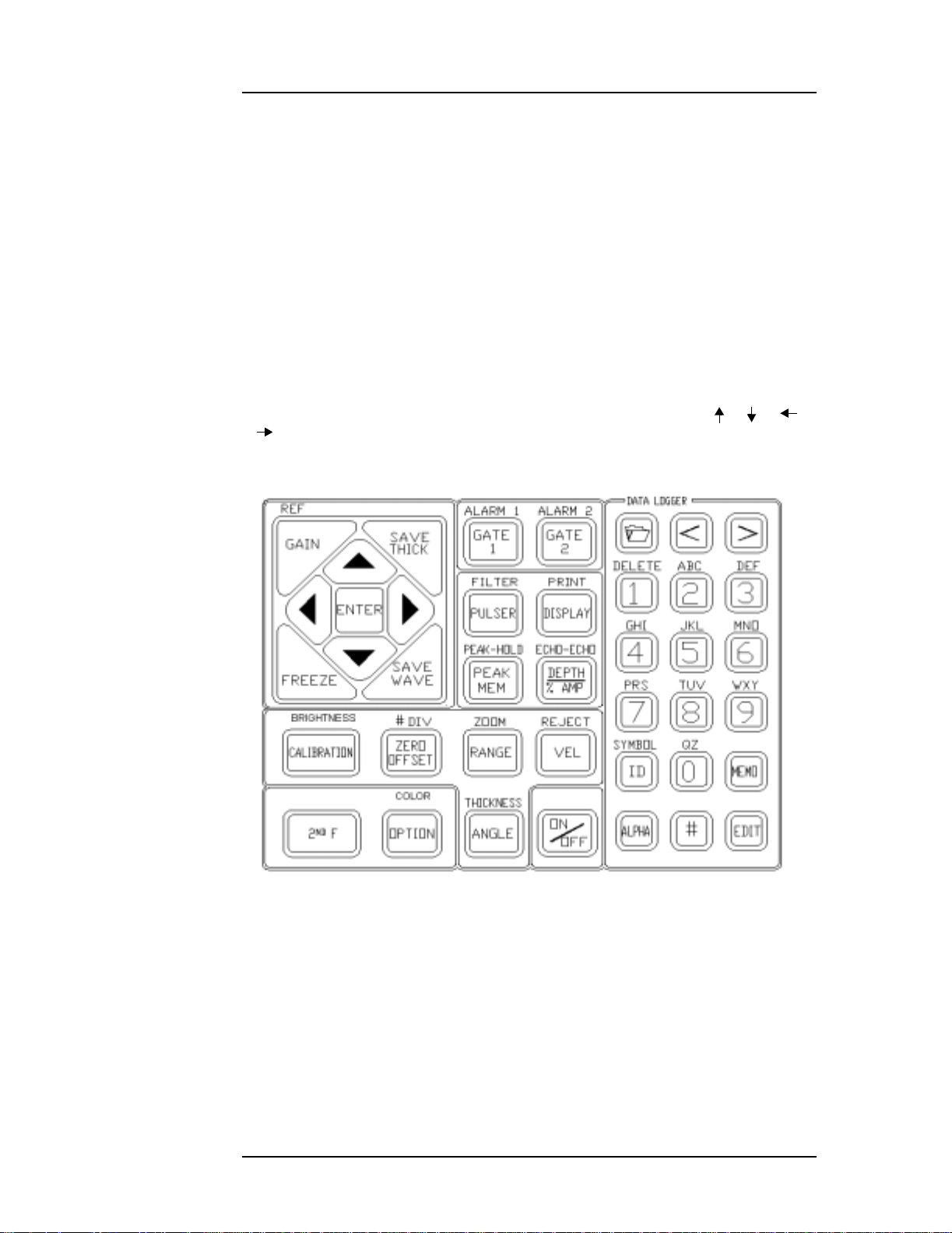
The keypad is grouped and color-coded according to function. The outlined section of
yellow keys on the left side of the keypad is used primarily for calibrating. The separate
group of grey keys on top are the function keys, designed to provide easy access to preset
parameter valu es. The EPOCH 4PLUS also has extensive data storage features controlled
by the datalogger keys at the right side of the keypad.
3.2.1 Enter Key
While you can access most functions directly via the instrument keypad, you can change
all essential ultrasonic controls by using of the
slewing keys [], [], [], and []. This method provides control of virtually all
instrument settings with the thumb of the left hand. Multiple presses of [ENTER] will
toggle through each of the instrument parameters. The parameter highlights when
activated. Use the [], [], [], or [] key to change an activated parameter value.
[ENTER] key and one o f the four gree n
Press the [ENTER] key multiple times to toggle through the instrument settings. To move
quickly through the sequence, press [ENTER] multiple times in succession or simply
hold down the key to reach the desired function.
3.2.2 Direct Access Operation
Most commonly used pa rameters al so have their own individua l keys to provi de direct
access to the pa rameter sett ing. To use the EPOCH 4PLUS in th is manner, press the
appropriate ke y to change t he parameter an d then eithe r press one of the function keys
(F1-F5) to select preset values, or adjust the value using the [], [], [], and []
slewing keys. For example to change the gain, press [GAIN]. Press [F1], [F2], [F3], [F4],
or [F5] to select one of the preset dB steps or use the slewing keys for fine adjustments.
In some cases the parameter appears as a second function above another key. To change
these parameters, press [2nd F] and then the appropriate key to access that parameter.
Whenever a function is opened in the full screen display, the EPOCH 4PLUS provides
prompts in the Abbreviated Statu s window dir ectly above the A-Scan di splay on the l eft
side.
3.3 Summarizing Keyp ad Functions
The EPOCH 4PLUS has two keypads. The top keypad, located directly underneath the
display, is made up of five function keys: [F1], [F2], [F3], [F4], and [F5].
10
Managing Basic Operations
When an operator accesses a parameter fro m the main keypad, preset valu e s are displayed
at the bottom of the screen. Each preset value has a corresponding function key. For
example, press [RANGE] to view various preset range values at the bottom of the display.
Press any one of the function keys to set the range to that displayed value.
The main keypad is laid out with functional grouping of keys for easy identification. The
main keypad is divided in two sections. The right side of the keypad, which resembles a
telephone keypa d, is used e xclusively f or datalogg ing purpose s. The left si de of the
keypad contai ns the prima ry operating k eys of the EPOCH 4PLUS. Most pa ramete rs on
the EPOCH 4PLUS can be directly accessed by pressing the appropriately labelled key.
Some parameters a re second fun ctions. The se can be acce ssed by firs t pressing [2nd F]
and then the desired function. The second function is written directly above the key. For
example, to access ZOOM, press [2nd F] and then [RA NGE].
Once you acces s a parameter, change it t hrough one of two methods. Use the function keys
to directly ac cess prese t values. Alt ernately, use the gree n slewing k eys ([], [], [],
and []) to change the parameter in smaller increments.
Part # 910-250C
Figure 1 Engl ish Keypad
11
EPOCH 4PLUS
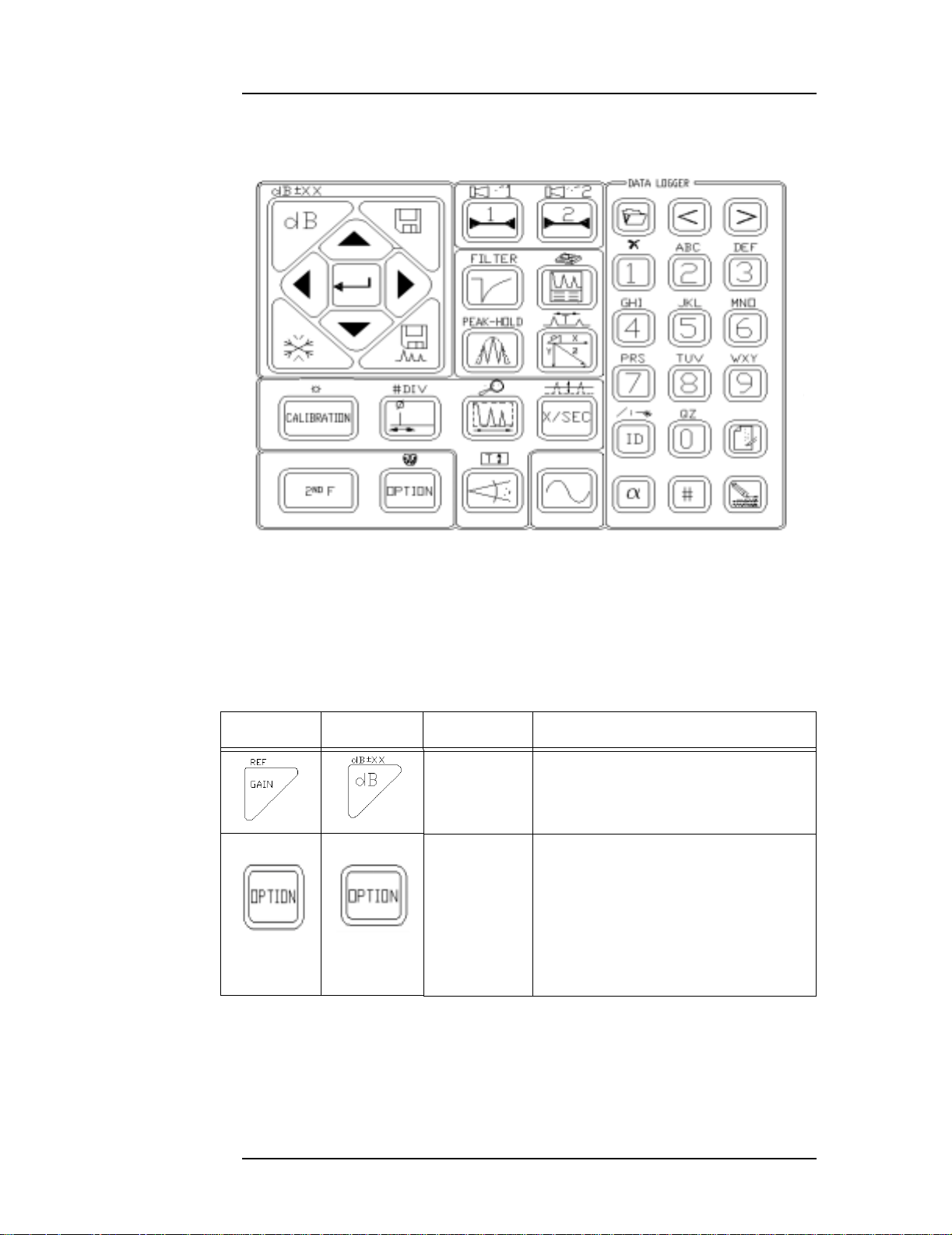
Figure 2 International Keypad
3.3.1 Main Keypad Functions
English Int’l Color Function
COLOR COLOR White Option: Accesses the instrument’ s
Table 3 Main Keypad Functions
Blue Sensitivity: Adjusts system sensitivity.
setup menu and software options .
12
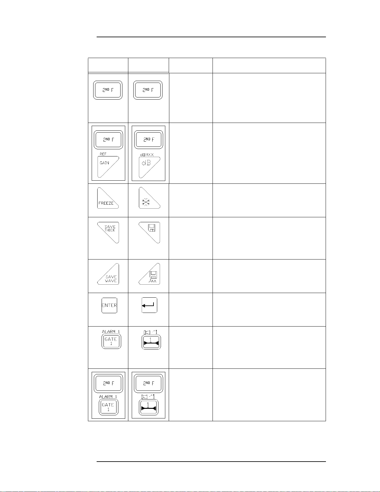
English Int’l Color Function
White 2nd Function: Press the [2nd F] key
with a key that has dual functio ns (the
main function written on the ke y; the
secondary function writt en above the
key), and the secondary functi on
becomes active.
Managing Basic Operations
White
Reference Level: Sets a gain refe rence
level and allows addition of scanning
gain in 6 dB or 0.1 dB increments.
Blue
Blue Screen Freeze: Holds display ed
waveform until [FREEZE] is pre ssed a
second time.
Purple Save Thickness Reading: Saves
displayed thickness reading in current
file. If the EPOCH 4PLUS is in Time-
of-Flight mode, the val ue will be in
microseconds.
Purple Save Wavef orm: Saves the current
waveform and instrument setup
parameters in current file.
Purple Enter: Press this key multiple times to
toggle through t he setup p arameters.
Part # 910-250C
Red Gate 1: Contr ols the position ing of
Gate 1 on the d isplay. Press this key
multiple times, or use the func tion keys,
to access Gate 1 Start, Gat e 1 Wi dth,
and Gate 1 Level.
White
Gate 1 Ala rm: Act ivates the alarm
mode for Gate 1. Use the function keys
to access the Threshold or Mi nimum
Depth Alarm.
Red
Table 3 Main Keypad Functions (Continued)
13
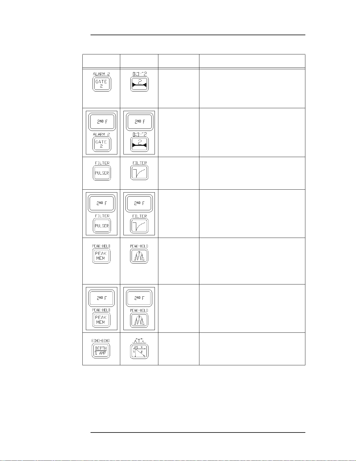
EPOCH 4PLUS
English Int’l Color Function
Red Gate 2: Controls the posit ioning of
Gate 2 on the d isplay. Press this key
multiple times, or use the func tion keys,
to access Gate 2 Start, Gat e 2 Wi dth,
and Gate 2 Level.
White
Gate 2 Ala rm: Act ivates the alarm
mode for Gate 2. Use the f unction Keys
to select the Threshold or Mini mum
Depth Alarm .
Red
Orange Pulser: Press this key multiple times to
toggle through the pulser parameters.
Use the function keys to sel ect preset
values for each pulser pa rameter.
White
Filter: Moves directly to filter
parameters.
Orange
Orange Peak Memory Function: Activates
the Peak Memory func tion allo wing
continuous accumula tion of pe ak
envelope data with the li ve waveform.
Press this key again to deactivate the
function.
14
White
Peak Hold Function: Activates the
Peak Hold function, which allows yo u
to capture a screen while allowing the
view of the live waveform. Pres s this
Orange
key sequence a second time to
deactivate the funct ion.
Orange Depth/% Amplitude: Allows
selection and display of pea k depth,
edge depth, signal a mplitude, or time of
flight data.
Table 3 Main Keypad Functions (Continued)
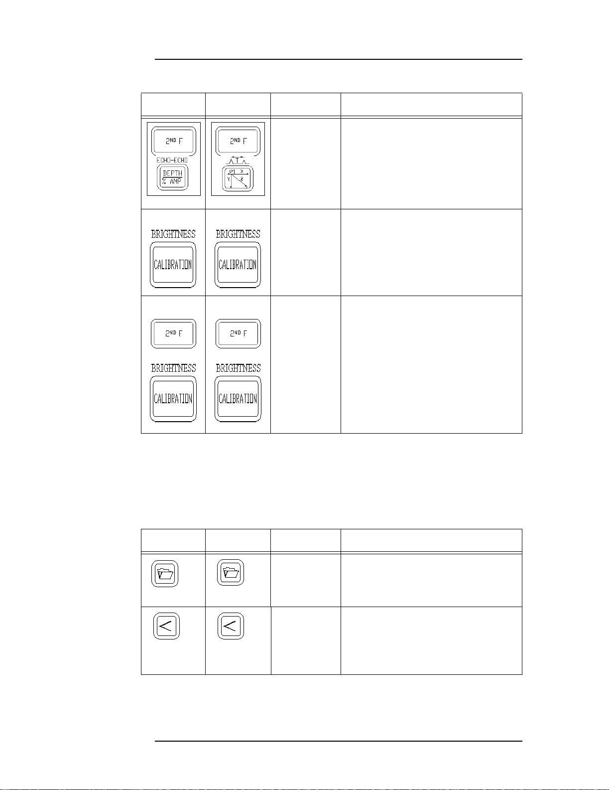
English Int’l Color Function
Managing Basic Operations
White
Echo-to-Echo Measurement :
Activates the Echo-to-Echo
Measurement mode. This
automatically opens Gat e 2 (if it is not
Orange
already active) an d allows you to select
edge to edge or peak to peak
measurement using the func tion keys.
Yellow Auto Calibration: Initiates the
EPOCH 4PLUS Auto Calibratio n
feature in conjunct ion with the [ZERO
OFFSET] and [VELOCITY] keys.
White
BRIGHTNESS Adjustment: Adjusts
the brightness of the Liqui d Crystal
Display (LCD).
Yellow
Table 3 Main Keypad Functions (Continued)
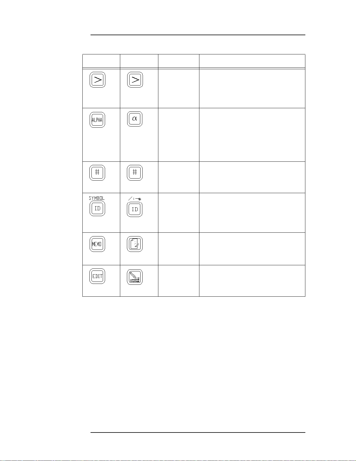
3.3.2 Datalogger Keypad Functions
English Int’l Color Function
Blue Open Datalogger: Opens the EPOCH
Blue Move Cursor Left: Moves the cursor
Table 4 Datalogger Keypad Functions
4PLUS datalogger/memory screen .
to the left one space each time this key
is pressed when the datal ogger is
opened, and you are entering/e diting a
directory name, filename, etc.
Part # 910-250C
15
EPOCH 4PLUS
English Int’l Color Function
Blue Move Cursor Right: Moves the cursor
to the right one space each time this key
is pressed when the datal ogger is
opened, and you are entering/e diting a
directory name, filename, etc.
White Alpha Entry: Allows entry of the
characters that are in beige-colored text
above the numbers keys. This includes
entry of the letters “A” throug h “Z”, the
entry of symbols (above the [ID] key ,
and the Delete function above the [1]
key).
Yellow Number Entry: Allows entry of the
number keys [0] through [9].
Blue ID Entry: Allows entry of an ID
(Identifier) location code. This ID
could be a new location code or editing
of a current one.
Blue Memo Entry: Allows ent ry of notes/
comments regarding the ins pection
data.
Blue Database Edit: Allows you to edit an
existing directory or fi le name when in
the datalogger/me mory scre en.
Table 4 Datalogger Keypad Functions (Continued)
16
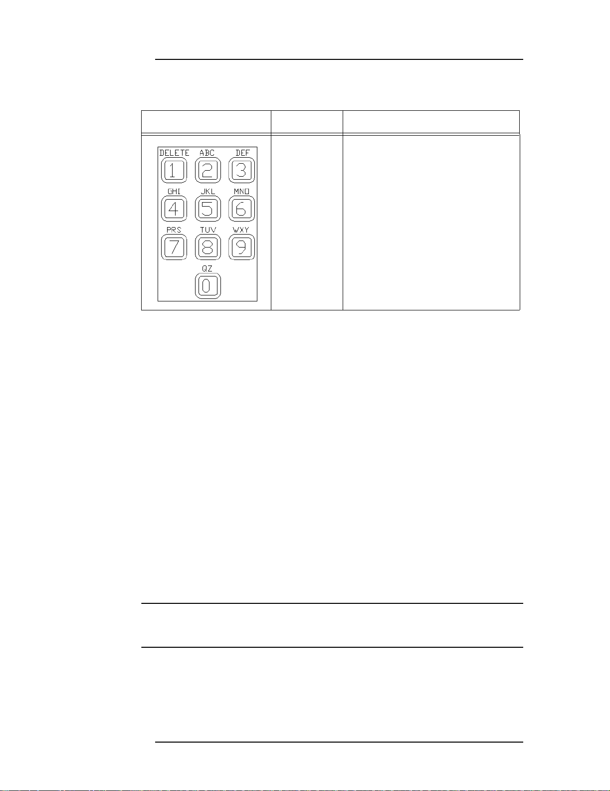
KEYS COLOR FUNCTION
Yellow Alphanumeric Entry: Entry of
alphanumeric character s. The
numeric characters are ent ered after
pressing the [#] key . The alpha
characters are entered a fter pres sing
the [ALPHA] key.
The Delete function is use d to erase a
number or character .
Note: The internationa l keypad uses
an X symbol instead of the Delete
label over the [1] key.
Table 5 Datalogger Alphanumeric Keypad Funct ions
Managing Basic Operations
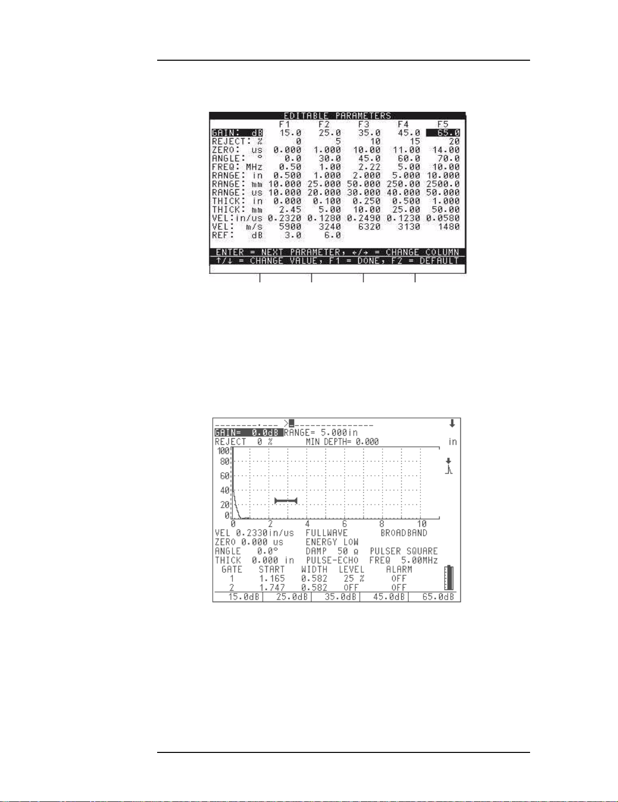
3.4 Editable Parameters Software
Using the Editable Parameters option, you can customize some of the values that appear
above the [F1] to [F5] k eys. These ar e the values that the EPOCH 4 PLUS recalls
automatically when the corresponding [F] key is pressed. You can edit the following
parameters:
•Gain
• Reference Gain
•Reject
• Zero Offset
•Angle
• Frequency
•Range
• Thickness
•Velocity
Note: Parameters that contain text, such as Rectification, cannot be adjusted. Also,
parameters that are limited by hardware and/or software constraints such as
Damping cannot be ad justed.
Part # 910-250C
To activate the Editable Parameters menu, follow these steps:
1. Press the [OPTION] key.
2. Use the slewing keys to select the Editable Parameters option.
17
EPOCH 4PLUS
Figure 3 Selecting the Editable Parameters Option
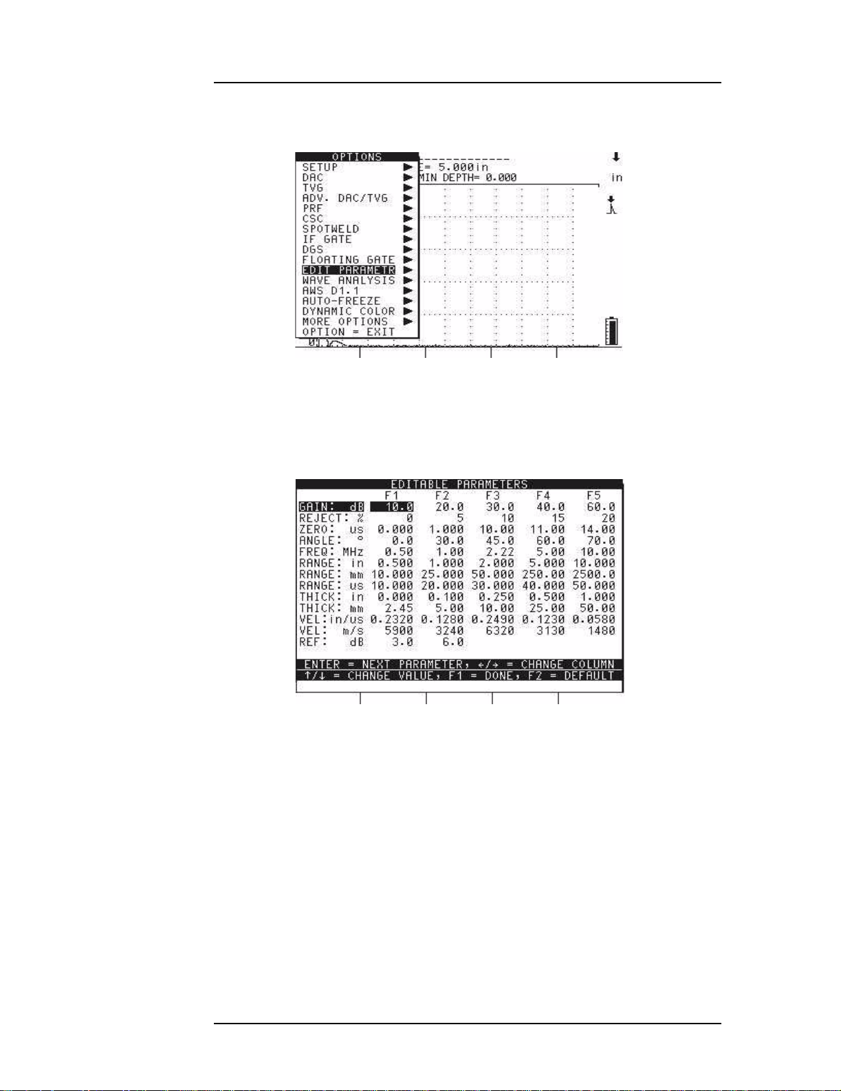
3. Press [ENTER]. The Edit able Paramet ers screen opens:
18
Figure 4 Viewing the Editable Parameters Screen
4. Press the [ENTER] key to move downward to different parameters.
5. Use the left and right slewing keys to select which [F1] - [F5] parameter to edit. Edit
each parameter us ing the up and d own slewing keys .
Managing Basic Operations
Figure 5 Editing the Gain Parameter
6. Press the [F1] key, when you have finished editing the parameters, to save the settings
and return to the Options menu.
When you select one of the parameters that you edited, the new preset values appear
above the [F] keys.
Figure 6 Viewing New Pres et Va lues
3.5 Color Settings
The EPOCH 4PLUS is capab le of displayi ng a maximum of ei ght (8) color s. You can
customize the color of any of the following:
Part # 910-250C
19

EPOCH 4PLUS
• Live A-Scan
• Peak Memory /Peak Hold A-Scan
• Gates (all gates may be the same color depending on color availability)
• Text (para meters, p opup boxes, and option menu ) and Grid
• DAC, TVG, DGS, and oth er curves
• Background
You have the option to use a dynamic color change of the waveform, which means that the
waveform may be eit her red, yello w, or green based on alarm conditio ns.
To customize colors, follow these steps:
1. Press [2nd F], [CALIBRATION] (Color). The adjustable items will appear above the F1- F5 keys.
2. Press the appropriate key to adjust the color of the display.
3.6 Managing the D isplay
The EPOCH 4PLUS can present the A-Scan in two different display formats – split screen
and full screen. A split screen presents simultaneous viewing of the waveform and all
instrument set-up data. The full screen presents a large, high resolution waveform and
important basic information.
Note: After the EPOCH 4PLUS is powered up and has completed the self test
routine, the split screen opens.
To set the display parameter, press [DISPLAY] to switch to full screen or press
[DISPLAY] again to switch back to the split screen.
3.6.1 Full Screen A-Scan Display
The full screen A-Scan presents a large, high resolution waveform and some basic data to
aid with interpretation of the display.
20
 Loading...