

Page 1

OmniScan SX
User’s Manual
DMTA-20043-01EN [U8778624] — Revision B
May 2013
This instruction manual contains essential information on how to use this Olympus product safely and effectively.
Before using this product, thoroughly review this instruction manual. Use the product as instructed.
Keep this instruction manual in a safe, accessible location.
Page 2

Olympus NDT, 48 Woerd Avenue, Waltham, MA 02453, USA
Copyright © 2013 by Olympus. All rights reserved. No part of this publication may
be reproduced, translated, or distributed without the express written permission of
Olympus.
This document was prepared with particular attention to usage to ensure the
accuracy of the information contained therein, and corresponds to the version of
the product manufactured prior to the date appearing on the title page. There
could, however, be some differences between the manual and the product if the
product was modified thereafter.
The information contained in this document is subject to change without notice.
Part number: DMTA-20043-01EN [U8778624]
Revision B
May 2013
Printed in Canada
All brands are trademarks or registered trademarks of their respective owners and
third party entities.
Page 3

DMTA-20043-01EN [U8778624], Rev. B, May 2013
Table of Contents
List of Abbreviations ...................................................................................... vii
Labels and Symbols ........................................................................................... 1
Important Information — Please Read Before Use ..................................... 7
Intended Use .......................................................................................................................... 7
Instruction Manual ................................................................................................................ 7
Instrument Compatibility ..................................................................................................... 7
Repair and Modification ....................................................................................................... 8
Safety Symbols ....................................................................................................................... 8
Safety Signal Words ............................................................................................................... 9
Note Signal Words ................................................................................................................. 9
Safety ..................................................................................................................................... 10
Warnings ............................................................................................................................... 10
Battery Precautions .............................................................................................................. 11
Equipment Disposal ............................................................................................................ 12
WEEE Directive .................................................................................................................... 12
China RoHS .......................................................................................................................... 12
Korea Communications Commission (KCC) ................................................................... 13
EMC Directive Compliance ................................................................................................ 13
FCC (USA) Compliance ...................................................................................................... 13
ICES-001 (Canada) Compliance ........................................................................................ 14
Warranty Information ......................................................................................................... 14
Technical Support ................................................................................................................ 15
Introduction ...................................................................................................... 17
1. Package Content ......................................................................................... 19
Table of Contents iii
Page 4

DMTA-20043-01EN [U8778624], Rev. B, May 2013
2. Overview of the OmniScan SX ............................................................... 21
2.1 Display Touch Screen ............................................................................................... 22
2.2 Main Control Area .................................................................................................... 22
2.3 Power Key .................................................................................................................. 23
2.4 Help Key ..................................................................................................................... 23
2.5 Indicator Lights ......................................................................................................... 23
2.5.1 Power Indicator Light .................................................................................... 23
2.5.2 Acquisition Indicator Light ........................................................................... 24
2.5.3 Alarm Indicator Lights .................................................................................. 24
2.6 Left Side Panel ........................................................................................................... 24
2.7 Right Side Panel ........................................................................................................ 26
2.8 Top Panel .................................................................................................................... 27
2.9 Rear Panel ................................................................................................................... 28
3. Basic Operation .......................................................................................... 33
3.1 Turning On and Off the OmniScan SX ................................................................... 33
3.2 Sleep Mode ................................................................................................................. 34
3.3 Automatic Start-Up Mode ....................................................................................... 35
3.4 Power Supply Management .................................................................................... 35
3.4.1 DC Power Adaptor ........................................................................................ 36
3.4.2 Lithium-Ion Battery ....................................................................................... 37
3.4.2.1 Battery Status Indicators .................................................................... 38
3.4.2.2 Battery Discharge ................................................................................ 38
3.4.2.3 Battery Removal and Installation ...................................................... 39
3.4.2.4 Battery Charging ................................................................................. 40
3.4.2.5 Maximizing the Performance of Lithium-Ion Batteries ................. 41
3.4.2.6 Used Battery Disposal ......................................................................... 42
3.4.2.7 Warnings on Battery Use .................................................................... 43
3.5 Peripheral Connection .............................................................................................. 43
3.6 OmniScan SX Software Installation ........................................................................ 45
4. Maintenance ................................................................................................ 47
4.1 Preventative Maintenance ....................................................................................... 47
4.2 Instrument Cleaning ................................................................................................. 47
4.2.1 Casing Cleaning ............................................................................................. 47
4.2.2 Screen and Screen Protector Cleaning ........................................................ 48
4.3 Replacing the Touch-Screen Protector ................................................................... 48
5. Troubleshooting ......................................................................................... 51
5.1 Start-Up Problems ..................................................................................................... 51
5.2 Battery Charging Problems ..................................................................................... 51
iv Table of Contents
Page 5

DMTA-20043-01EN [U8778624], Rev. B, May 2013
5.3 Battery Life Problems ............................................................................................... 52
6. Specifications .............................................................................................. 53
7. Connector References ................................................................................ 61
7.1 Scanner Interface Connector ................................................................................... 62
7.2 Scanner Interface Adaptor ....................................................................................... 66
Appendix: Compatibility Tables ................................................................... 69
List of Figures ................................................................................................... 71
List of Tables ..................................................................................................... 73
Index ................................................................................................................... 75
Table of Contents v
Page 6

DMTA-20043-01EN [U8778624], Rev. B, May 2013
vi Table of Contents
Page 7

List of Abbreviations
DMTA-20043-01EN [U8778624], Rev. B, May 2013
DC direct current
EFUP environment-friendly use period
IATA International Air Transport Asso-
ciation
ICAO International Civil Aviation Orga-
nization
IMO International Maritime Organiza-
tion
LCD liquid crystal display
NDT nondestructive testing
PA phased array
RH relative humidity
SDHC secure digital high capacity
TFT thin film transistor
USDOT US Department of Transportation
UT ultrasonic testing
WEEE waste electrical and electronic
equipment
List of Abbreviations vii
Page 8

DMTA-20043-01EN [U8778624], Rev. B, May 2013
viii List of Abbreviations
Page 9

DMTA-20043-01EN [U8778624], Rev. B, May 2013
Location of rating and
identification labels
(see Table 1 on page 2).
Labels and Symbols
Safety-related labels and symbols are attached to the instrument at the locations
shown in Figure i-1 on page 1. If any or all of the labels or symbols are missing or
illegible, please contact Olympus.
Figure i-1 Labels location
Labels and Symbols 1
Page 10

DMTA-20043-01EN [U8778624], Rev. B, May 2013
Table 1 Content of the rating label
The CE marking is a declaration that this product conforms to
all the applicable directives of the European Community. See
the Declaration of Conformity for details. Contact your Olympus
representative for more information.
Content
2 Labels and Symbols
The C-Tick label indicates that the product complies with the
applicable standard, and establishes a traceable link between
the equipment and the manufacturer, importer, or agent
responsible for compliance, and for placing it on the
Australian market.
The WEEE symbol indicates that the product must not be
disposed of as unsorted municipal waste, but should be
collected separately.
Page 11

Table 1 Content of the rating label (continued)
The China RoHS mark indicates the product’s EnvironmentFriendly Use Period (EFUP). The EFUP is defined as the
number of years for which listed controlled substances will not
leak or chemically deteriorate while in the product. The EFUP
for the OmniScan SX has been determined to be 15 years.
Note: The Environment-Friendly Use Period (EFUP) is not
meant to be interpreted as the period assuring functionality
and product performance.
Seller and user shall be noticed that this equipment is suitable
for electromagnetic equipment for office work (class A) and it
can be used outside home.
The direct current symbol.
The DC adaptor polarity symbol.
M/N Model number
DMTA-20043-01EN [U8778624], Rev. B, May 2013
Mfg. Date Manufacturing date
S/N Serial number
Labels and Symbols 3
Page 12
DMTA-20043-01EN [U8778624], Rev. B, May 2013
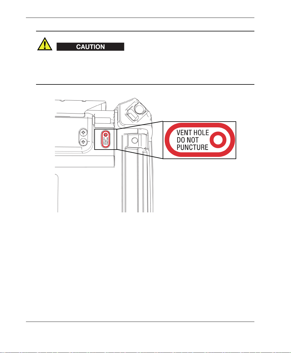
The membrane vent (see Figure i-2 on page 4) is used to counterbalance the internal
and external pressures and to maintain the instrument watertightness. Do not
puncture the membrane vent. When the membrane vent is punctured, the instrument
fails to comply with the IP66 rating.
4 Labels and Symbols
Figure i-2 Membrane vent location
Page 13
DMTA-20043-01EN [U8778624], Rev. B, May 2013
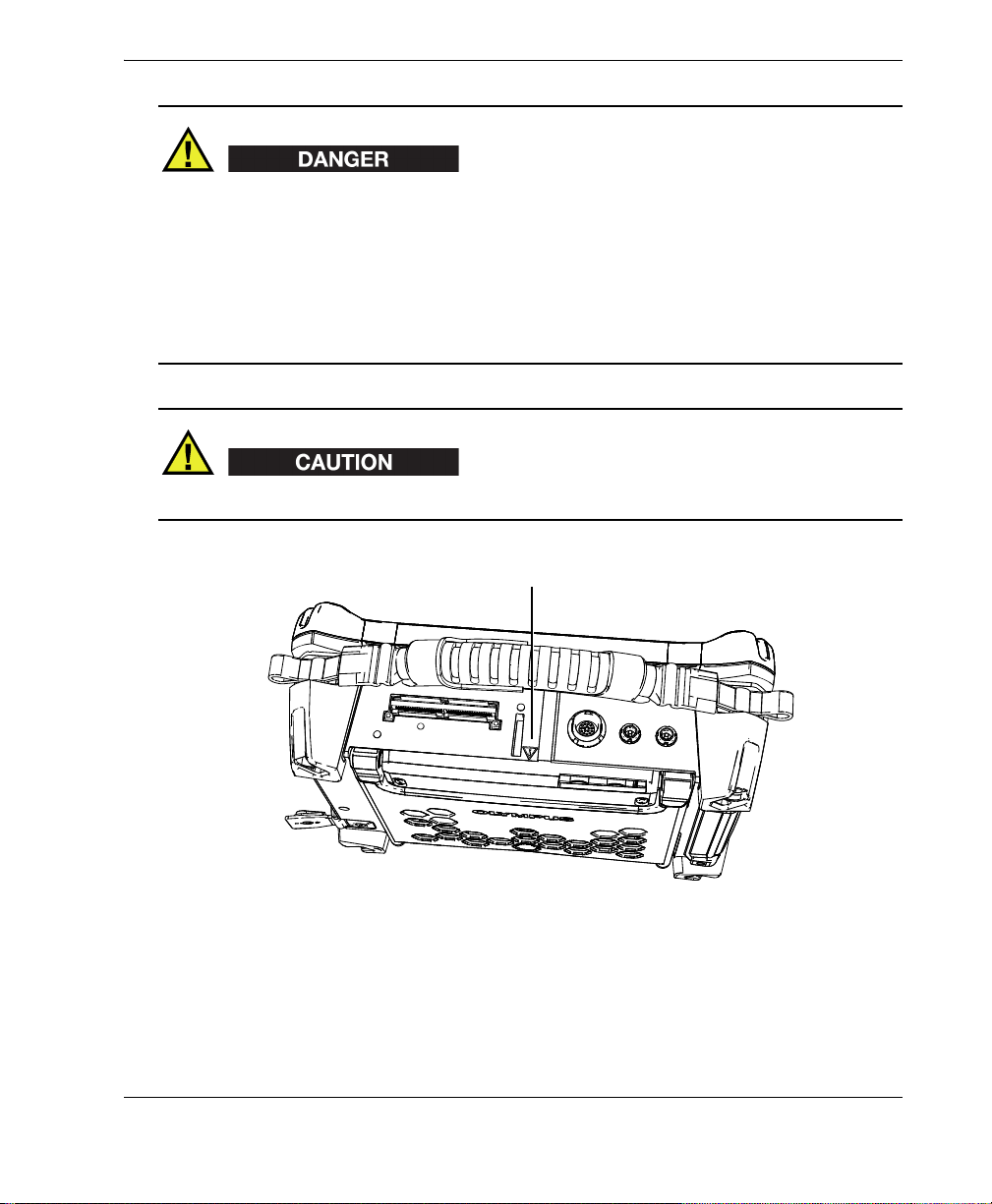
Warning symbol
• To reduce the risk of electric shock, avoid touching the inner conductor of the
probe connectors. Up to 340 V can be present on the inner conductor of the
ultrasonic testing (UT) connectors, and up to 115 V can be present on the phased
array (PA) connector. The warning symbol near the PA and UT connectors signals
this electric shock risk (see Figure i-3 on page 5).
• Reinforced insulation must be provided for the probes connected to the
OmniScan SX instrument.
Use only compatible Olympus probes.
Figure i-3 Warning symbol on top of the OmniScan SX
Labels and Symbols 5
Page 14

DMTA-20043-01EN [U8778624], Rev. B, May 2013
Warning symbol
The warning symbol on the battery compartment door (see Figure i-4 on page 6)
signals that precautions must be taken concerning the battery. See section 3.4.2.7 on
page 43.
6 Labels and Symbols
Figure i-4 Warning symbol on battery compartment door
Page 15
DMTA-20043-01EN [U8778624], Rev. B, May 2013
Important Information — Please Read Before Use
Intended Use
The OmniScan SX is designed to perform nondestructive inspections on industrial
and commercial materials.
Do not use the OmniScan SX for any purpose other than its intended use. It must
never be used to inspect or examine human or animal body parts.
Instruction Manual
This instruction manual contains essential information on how to use this Olympus
product safely and effectively. Before using this product, thoroughly review this
instruction manual. Use the product as instructed.
Keep this instruction manual in a safe, accessible location.
Instrument Compatibility
Refer to the Appendix on page 69 to confirm that the OmniScan SX is compatible with
the auxiliary equipment being used.
Important Information — Please Read Before Use 7
Page 16

DMTA-20043-01EN [U8778624], Rev. B, May 2013
Always use equipment and accessories that meet Olympus specifications. Using
incompatible equipment could cause malfunction and/or equipment damage, or
injury.
Repair and Modification
The OmniScan SX does not contain any user-serviceable parts. Opening the
instrument might void the warranty.
In order to prevent human injury and/or equipment damage, do not disassemble,
modify, or attempt to repair the instrument.
Safety Symbols
The following safety symbols might appear on the instrument and in the instruction
manual:
General warning symbol
This symbol is used to alert the user to potential hazards. All safety messages that
follow this symbol shall be obeyed to avoid possible harm or material damage.
High voltage warning symbol
This symbol is used to alert the user to potential electric shock hazards greater
than 1000 volts. All safety messages that follow this symbol shall be obeyed to
avoid possible harm.
8 Important Information — Please Read Before Use
Page 17
DMTA-20043-01EN [U8778624], Rev. B, May 2013
Safety Signal Words
The following safety symbols might appear in the documentation of the instrument:
The DANGER signal word indicates an imminently hazardous situation. It calls
attention to a procedure, practice, or the like, which, if not correctly performed or
adhered to, could result in death or serious personal injury. Do not proceed beyond a
DANGER signal word until the indicated conditions are fully understood and met.
The WARNING signal word indicates a potentially hazardous situation. It calls
attention to a procedure, practice, or the like, which, if not correctly performed or
adhered to, could result in death or serious personal injury. Do not proceed beyond a
WARNING signal word until the indicated conditions are fully understood and met.
The CAUTION signal word indicates a potentially hazardous situation. It calls
attention to an operating procedure, practice, or the like, which, if not correctly
performed or adhered to, could result in minor or moderate personal injury, material
damage, particularly to the product, destruction of part or all of the product, or loss of
data. Do not proceed beyond a CAUTION signal word until the indicated conditions
are fully understood and met.
Note Signal Words
The following safety symbols could appear in the documentation of the instrument:
The IMPORTANT signal word calls attention to a note that provides important
information, or information essential to the completion of a task.
Important Information — Please Read Before Use 9
Page 18
DMTA-20043-01EN [U8778624], Rev. B, May 2013
The NOTE signal word calls attention to an operating procedure, practice, or the like,
which requires special attention. A note also denotes related parenthetical
information that is useful, but not imperative.
The TIP signal word calls attention to a type of note that helps you apply the
techniques and procedures described in the manual to your specific needs, or
provides hints on how to effectively use the capabilities of the product.
Safety
This instrument is an instrument of Class 1 and installation category II. Before turning
on the instrument, verify that the correct safety precautions have been taken (see the
following warnings). In addition, note the external markings on the instrument,
which are described under “Safety Symbols”.
Warnings
General Warnings
• Carefully read the instructions contained in this instruction manual prior to
turning on the instrument.
• Keep this instruction manual in a safe place for further reference.
• Follow the installation and operation procedures.
• It is imperative to respect the safety warnings on the instrument and in this
instruction manual.
• If the equipment is used in a manner not specified by the manufacturer, the
protection provided by the equipment could be impaired.
• Do not install substitute parts or perform any unauthorized modification to the
instrument.
10 Important Information — Please Read Before Use
Page 19
DMTA-20043-01EN [U8778624], Rev. B, May 2013
• Service instructions, when applicable, are for trained service personnel. To avoid
the risk of electric shock, do not perform any work on the instrument unless
qualified to do so. For any problem or question regarding this instrument, contact
Olympus or an authorized Olympus representative.
Electrical Warnings
• Before turning on the instrument, you must connect the protective earth terminal
of the instrument to the protective conductor (mains) of the power cord. The
mains plug shall only be inserted into a socket outlet provided with a protective
earth contact. Never negate the protective action by using an extension cord
(power cable) without a protective conductor (grounding).
• Only use fuses with the required rated current, voltage, and specified type
(normal-blow, slow-blow, quick-acting, etc.). Do not use repaired fuses or shortcircuited fuse holders. Doing so could cause electric shock or create a fire hazard.
• If there is any possibility that the ground protection could be impaired, you must
make the instrument inoperative and secure it against any unintended operation.
• The instrument must only be connected to a power source corresponding to the
type indicated on the rating label.
Battery Precautions
Transportation of lithium-ion batteries is regulated by the United Nations under the
United Nations Recommendations on the Transport of Dangerous Goods. It is
expected that governments, intergovernmental organizations, and other international
organizations shall conform to the principles laid down in these regulations, thus
contributing to worldwide harmonization in this field. These international
organizations include the International Civil Aviation organization (ICAO), the
International Air Transport Association (IATA), the International Maritime
Organization (IMO), the US Department of Transportation (USDOT), and others.
Please contact the transporter and confirm current regulations before transportation
of lithium-ion batteries.
Important Information — Please Read Before Use 11
Page 20

DMTA-20043-01EN [U8778624], Rev. B, May 2013
Equipment Disposal
Before disposing of the OmniScan SX, check your local laws, rules, and regulations,
and follow them accordingly.
WEEE Directive
In accordance with European Directive 2002/96/EC on Waste Electrical
and Electronic Equipment (WEEE), this symbol indicates that the
product must not be disposed of as unsorted municipal waste, but
should be collected separately. Refer to your local Olympus distributor
for return and/or collection systems available in your country.
China RoHS
China RoHS is the term used by industry generally to describe legislation
implemented by the Ministry of Information Industry (MII) in the People’s Republic
of China for the control of pollution by electronic information products (EIP).
The China RoHS mark indicates the product’s EnvironmentFriendly Use Period (EFUP). The EFUP is defined as the number of
years for which listed controlled substances will not leak or
chemically deteriorate while in the product. The EFUP for the
OmniScan SX has been determined to be 15 years.
Note: The Environment-Friendly Use Period (EFUP) is not meant
to be interpreted as the period assuring functionality and product
performance.
12 Important Information — Please Read Before Use
Page 21

DMTA-20043-01EN [U8778624], Rev. B, May 2013
Korea Communications Commission (KCC)
A 급 기기 ( 업무용 방송통신기자재 )
이 기기는 업무용 (A 급 ) 전자파적합기기로서 판 매자 또는 사용자는 이 점을주의하시
기 바라 며 , 가정외의 지역에서 사용하는 것을 목적으로 합니다 .
EMC Directive Compliance
This equipment generates and uses radio-frequency energy and, if not installed and
used properly (that is, in strict accordance with the manufacturer’s instructions), may
cause interference. The OmniScan SX has been tested and found to comply with the
limits for an industrial device in accordance with the specifications of the EMC
directive.
To maintain OmniScan SX compliance with the emissions requirements of the EMC
directive, the following conditions must be met:
• All cables used to connect the equipment must have an overall shielding to ensure
electromagnetic compatibility and optimal performance.
• Ferrite clamp filters must be attached to the cables connected to the OmniScan SX.
For details, see “Ferrite clamp filters” on page 43.
FCC (USA) Compliance
This equipment has been tested and found to comply with the limits for a Class A
digital device, pursuant to Part 15 of the FCC Rules. These limits are designed to
provide reasonable protection against harmful interference when the equipment is
operated in a commercial environment. This equipment generates, uses, and can
radiate radio frequency energy, and if not installed and used in accordance with the
instruction manual, might cause harmful interference to radio communications.
Important Information — Please Read Before Use 13
Page 22

DMTA-20043-01EN [U8778624], Rev. B, May 2013
Operation of this equipment in a residential area is likely to cause harmful
interference, in which case you will be required to correct the interference at your own
expense.
ICES-001 (Canada) Compliance
This Class A digital apparatus complies with Canadian ICES-001.
Cet appareil numérique de la classe A est conforme à la norme NMB-001 du Canada.
Warranty Information
Olympus guarantees your Olympus product to be free from defects in materials and
workmanship for a specific period, and in accordance with conditions specified in the
Olympus NDT Terms and Conditions available at http://www.olympusims.com/en/terms/.
The Olympus warranty only covers equipment that has been used in a proper
manner, as described in this instruction manual, and that has not been subjected to
excessive abuse, attempted unauthorized repair, or modification.
Inspect materials thoroughly on receipt for evidence of external or internal damage
that might have occurred during shipment. Immediately notify the carrier making the
delivery of any damage, because the carrier is normally liable for damage during
shipment. Retain packing materials, waybills, and other shipping documentation
needed in order to file a damage claim. After notifying the carrier, contact Olympus
for assistance with the damage claim and equipment replacement, if necessary.
This instruction manual explains the proper operation of your Olympus product. The
information contained herein is intended solely as a teaching aid, and shall not be
used in any particular application without independent testing and/or verification by
the operator or the supervisor. Such independent verification of procedures becomes
increasingly important as the criticality of the application increases. For this reason,
Olympus makes no warranty, expressed or implied, that the techniques, examples, or
procedures described herein are consistent with industry standards, nor that they
meet the requirements of any particular application.
Olympus reserves the right to modify any product without incurring the
responsibility for modifying previously manufactured products.
14 Important Information — Please Read Before Use
Page 23

DMTA-20043-01EN [U8778624], Rev. B, May 2013
Technical Support
Olympus is firmly committed to providing the highest level of customer service and
product support. If you experience any difficulties when using our product, or if it
fails to operate as described in the documentation, first consult the user’s manual, and
then, if you are still in need of assistance, contact our After-Sales Service. To locate the
nearest service center, visit the Service Centers page at: http://www.olympusims.com.
Important Information — Please Read Before Use 15
Page 24

DMTA-20043-01EN [U8778624], Rev. B, May 2013
16 Important Information — Please Read Before Use
Page 25

DMTA-20043-01EN [U8778624], Rev. B, May 2013
Introduction
Olympus is a long-standing leader in NDT (nondestructive testing) test platforms,
with thousands of OmniScan units in use throughout the world. With the
OmniScan SX, the user benefit from a lighter, smaller, and more portable solution that
meet requirements for single group fully encoded phased array inspection.
Refer to the OmniScan MXU Software User’s Manual for information on software
functions.
The illustrations used in this manual were prepared with the instrument version
available at the time of publication, and may differ slightly in appearance from the
version of the OmniScan SX instrument that you are using.
Introduction 17
Page 26

DMTA-20043-01EN [U8778624], Rev. B, May 2013
18 Introduction
Page 27

1. Package Content
Models
The OmniScan SX is available in two different models:
OMNISX-PA1664PR
Portable 16:64PR phased array acquisition unit (including one UT conventional
channel)
OMNISX-UT
Portable one-channel conventional UT acquisition unit
DMTA-20043-01EN [U8778624], Rev. B, May 2013
Accessories
The OmniScan SX comes standard with the following accessories:
• Cable ferrite clamp — Internal diameter of 4.8 mm
• Cable ferrite clamp — Internal diameter of 6.6 mm
• Cable ferrite clamp — Internal diameter of 9.0 mm
• 16-GB USB Flash drive
• 16-GB SDHC card
• Anti-glare screen protectors (2)
•Stylus
• Li-ion battery
• DC power adaptor
• Power cord (model varies according to country)
• Transport case
• USB Flash drive, which contains:
Package Content 19
Page 28

DMTA-20043-01EN [U8778624], Rev. B, May 2013
—MXU software
— OmniScan SX Getting Started Guide
— OmniScan SX User’s Manual
— OmniScan MXU Software User’s Manual
For a list of accessories and part numbers, see “Compatibility Tables” on page 69.
20 Chapter 1
Page 29

DMTA-20043-01EN [U8778624], Rev. B, May 2013
Main control
area
Function keys
Power key
Power
indicator light
Alarm indicator
lights
Display touch
screen
Acquisition
indicator
light
Help key
2. Overview of the OmniScan SX
The front panel of the OmniScan SX (see Figure 2-1 on page 21) contains all the main
controls and indicators, which are explained further in the following sections.
Figure 2-1 Front panel controls of the OmniScan SX
Overview of the OmniScan SX 21
Page 30

DMTA-20043-01EN [U8778624], Rev. B, May 2013
2.1 Display Touch Screen
The display touch screen acts as a pointing device. To click an interface element, touch
the screen surface lightly with your finger. Refer to the OmniScan MXU Software User’s
Manual for advanced operating instructions for the touch screen.
2.2 Main Control Area
The main control area is shown in Figure 2-1 on page 21. You can control the
OmniScan SX completely from this area if you wish. The main control area contains
three elements, which are described in Table 2 on page 22.
Table 2 Main control area
Element Name Description
Scroll knob Used to navigate through selections without
the need for a keyboard, mouse, or touch
screen. Turning the scroll knob in a clockwise
direction shifts a selection to the left
(horizontal list) or upward (vertical list). For
more information about using the scroll knob
with the OmniScan software, refer to the
OmniScan MXU Software User’s Manual.
22 Chapter 2
Accept key Used to confirm a selection.
Cancel key Used to cancel the current selection, or to go
back one level in the menu hierarchy.
Page 31

DMTA-20043-01EN [U8778624], Rev. B, May 2013
2.3 Power Key
The Power key (see Figure 2-1 on page 21) is used to start or shut down the
OmniScan SX, but also to enable or disable the sleep mode.
2.4 Help Key
The Help key (see Figure 2-1 on page 21) is located on the upper-right side of the
OmniScan SX front panel. Pressing this key displays the online help for the currently
selected function.
2.5 Indicator Lights
There are three types of indicator lights on the OmniScan SX front panel: power,
acquisition, and alarm. Each indicator light is described below.
2.5.1 Power Indicator Light
The power indicator light is located above the Power key. The color of this light
identifies the power status of the OmniScan SX (see Table 3 on page 23).
Table 3 Power indicator light statuses
Off The OmniScan SX is turned off.
Flashing orange The OmniScan SX is turned off. Battery is charging.
Orange The OmniScan SX is turned off. Battery charging is
complete.
Green • The OmniScan SX is turned on.
• The OmniScan SX is turned on and battery is charging.
Flashing
green/orange
The OmniScan SX is in sleep mode. The battery is
charging.
Overview of the OmniScan SX 23
Page 32

DMTA-20043-01EN [U8778624], Rev. B, May 2013
Table 3 Power indicator light statuses (continued)
Flashing green • The OmniScan SX is in sleep mode.
• The OmniScan SX is in sleep mode and battery
charging is complete.
Flashing red A critical factor (excessive temperature, very weak battery,
etc.) requires immediate attention.
2.5.2 Acquisition Indicator Light
The acquisition indicator light is located below the Play key ( ). The color of this
light indicates the operating mode of the OmniScan SX (see Table 4 on page 24).
Table 4 Acquisition indicator light statuses
Off Inspection mode
Orange Analysis mode
2.5.3 Alarm Indicator Lights
There are three alarm indicator lights located on the upper right corner of the
OmniScan SX. These lights only flash one color (red) and indicate the trigger status of
their respective alarms (set within the software).
For more details about the alarm indicator lights, refer to the OmniScan MXU Software
User’s Manual.
2.6 Left Side Panel
The left side panel of the OmniScan SX (see Figure 2-2 on page 25) contains various
input and output ports.
24 Chapter 2
Page 33

DMTA-20043-01EN [U8778624], Rev. B, May 2013
Memory card slot
Battery compartment door
SVGA output connector
USB ports
Battery compartment door
This door provides access to the battery compartment. Battery replacement is
covered in section 3.4.2.3 on page 39.
SVGA output
An external VGA or SVGA monitor that mirrors the OmniScan SX display may be
connected to this DB-15 port.
Memory card slot
Slot for inserting the Secure Digital High Capacity (SDHC) memory card.
USB ports (2)
The USB ports (see Figure 2-2 on page 25) accommodate USB peripherals such as
external keyboards, mice, storage devices, or printers.
Figure 2-2 Left side panel of the OmniScan SX
Overview of the OmniScan SX 25
Page 34

DMTA-20043-01EN [U8778624], Rev. B, May 2013
DC power adaptor plug
2.7 Right Side Panel
The right side panel of the OmniScan SX (see Figure 2-3 on page 26) contains the DC
power adaptor plug.
DC power adaptor plug
Used to connect an external DC power adaptor to the OmniScan SX.
26 Chapter 2
Figure 2-3 Right side panel of the OmniScan SX
Page 35

DMTA-20043-01EN [U8778624], Rev. B, May 2013
Scanner interface
UT connectors
PA connector
2.8 Top Panel
• To reduce the risk of electric shock, avoid touching the inner conductor of the
probe connectors. Up to 340 V can be present on the inner conductor of the UT
connectors, and up to 115 V can be present on the PA connector. The warning
symbol near the PA and UT connectors signals this electric shock risk.
• Reinforced insulation must be provided for the probes connected to the
OmniScan SX instrument.
Use only compatible Olympus probes.
There are four connectors located on the top panel of the OmniScan SX (see Figure 2-4
on page 27).
Figure 2-4 Top panel of the OmniScan SX (OmniSX-PA1664PR shown)
Overview of the OmniScan SX 27
Page 36

DMTA-20043-01EN [U8778624], Rev. B, May 2013
Phased array probe connector
LEMO connector
P1 (UT connector)
LEMO connector used for the transmission of ultrasonic signals when using the
pitch-catch inspection technique.
R1 (UT connector)
LEMO connector used for the reception of ultrasonic signals when using the
pitch-catch inspection technique.
Scanner interface
Used as an alarm output and control input.
PA connector
Used to connect a phased array probe.
The compatible probe connectors are presented in Figure 2-5 on page 28.
2.9 Rear Panel
28 Chapter 2
Figure 2-5 LEMO and phased array probe connectors
The rear panel consists of the heat sink and the support stand (see Figure 2-6 on
page 29).
Page 37

DMTA-20043-01EN [U8778624], Rev. B, May 2013
Support stand
Heat sink
Support stand fastener
Figure 2-6 Rear panel of the OmniScan SX
• To prevent the OmniScan SX from falling over, the support stand must be opened
to its maximum position when the instrument is desktop mounted.
• In order to prevent injury, do not place your fingers between the rear panel and
the instrument’s support stand (when unfolded).
• Injury can result when support stand is folded in stored position.
• Do not use the support stand as a handle. Using the support stand as a handle
could cause equipment damage or injury.
Overview of the OmniScan SX 29
Page 38

DMTA-20043-01EN [U8778624], Rev. B, May 2013
Fastening hole
Fastening hole
The rear panel is equipped with two fastening holes that can be used for attaching
accessories or for instrument mounting purposes (see Figure 2-7 on page 30 and
Figure 2-8 on page 31).
Figure 2-7 Fastening holes
30 Chapter 2
Page 39

DMTA-20043-01EN [U8778624], Rev. B, May 2013
44 mm 97 mm
92 mm
33 mm
59 mm
2 × M4
Figure 2-8 Fastening hole location and specifications
To prevent equipment damage, apply the following instructions when attaching
accessories to the OmniScan SX or when mounting the OmniScan SX to any surface.
• Use M4 × 0.7 mm screws with a nominal penetration length (into the instrument)
of 8 mm.
• Make sure that air can circulate freely between the OmniScan SX’s heat sink and
the accessory or mounting surface.
• When mounting the OmniScan SX to any surface:
— Always use the two fastening holes.
— Make sure that there is at least a 12 mm diameter surface contact area (see
Figure 2-9 on page 32) between the OmniScan SX and the supporting surface.
Overview of the OmniScan SX 31
Page 40

DMTA-20043-01EN [U8778624], Rev. B, May 2013
Minimum 12 mm
diameter surface
contact
• Only attach accessories weighing 3.4 kg (the weight of the OmniScan SX) or less.
Figure 2-9 Surface contact requirements
32 Chapter 2
Page 41

DMTA-20043-01EN [U8778624], Rev. B, May 2013
3. Basic Operation
This chapter describes the basic principles and procedures involved in operating the
OmniScan SX instrument.
3.1 Turning On and Off the OmniScan SX
This section explains how to turn on and off the OmniScan SX.
To turn on the OmniScan SX
Press the Power key for one second.
The system starts up and performs a memory check.
If the system encounters a problem during the start-up phase, the power indicator
light will indicate the nature of the problem using a color code (for details, see “Power
Indicator Light” in section 2.5 on page 23).
To turn off the OmniScan SX
1. Quickly press the Power key.
The “Select a command” message appears (see Figure 3-1 on page 34).
Basic Operation 33
Page 42

DMTA-20043-01EN [U8778624], Rev. B, May 2013
The Shut Down button
Figure 3-1 The Shut Down button
2. Select Shut Down (see Figure 3-3 on page 35).
A message asking you if you want to save your setup appears (see Figure 3-2 on
page 34).
Figure 3-2 Saving the setup
3. To save your setup, select Yes .
You can also turn off the OmniScan SX by pressing and holding the Power key for ten
seconds. However, your setup will NOT be saved.
3.2 Sleep Mode
The OmniScan SX can be put into sleep mode when not in use to conserve power.
To use the sleep mode
1. With the OmniScan SX turned on, quickly press the Power key.
34 Chapter 3
Page 43

DMTA-20043-01EN [U8778624], Rev. B, May 2013
The Sleep button
The “Select a command” message appears (see Figure 3-3 on page 35).
2. Select Sleep.
Figure 3-3 Sleep mode selection
3. To disable the sleep mode, quickly press the Power key.
The OmniScan SX returns to its previous state (inspection or analysis mode).
3.3 Automatic Start-Up Mode
The OmniScan SX has an automatic start-up mode: auto-boot. Use the auto-boot
mode to remotely start the OmniScan SX unit. When this mode is enabled, you do not
need to press the Power key to start the OmniScan SX. The OmniScan SX starts up
automatically when connected to a DC power adaptor. This mode is disabled by
default.
To activate the auto-boot
1. Turn off the OmniScan SX unit, remove the batteries, and then disconnect the DC
power adaptor.
2. Press and hold the Power key.
3. Connect the OmniScan SX to a DC power adaptor.
4. Wait for the power indicator light to blink two times, and then release the Power
key.
5. To deactivate the auto-boot, repeat steps 1 to 4.
3.4 Power Supply Management
The OmniScan SX is a portable instrument that can draw power from either a lithiumion battery or a DC power adaptor.
Basic Operation 35
Page 44

DMTA-20043-01EN [U8778624], Rev. B, May 2013
3.4.1 DC Power Adaptor
You can operate the OmniScan SX on AC power using the DC power adaptor (P/N:
OMNI-A-AC [U8767093]). The OMNI-A-AC has a universal AC power input, which
operates with any line voltage from 100 VAC to 120 VAC or from 200 VAC to
240 VAC, and at 50 Hz to 60 Hz line frequency.
The DC power adaptor is for indoor use only.
To use AC power
1. Connect the AC power cord to the DC power adaptor (P/N: OMNI-A-AC
[U8767093]) and to an appropriate power outlet.
• Use only the AC power cord supplied with the OmniScan SX. Do not use this AC
power cord with other products.
• The OmniScan SX must only be connected to a power source corresponding to the
type indicated on the rating plate. Therefore, use only the DC power adaptor that
is delivered with the OmniScan SX.
2. On the right-hand side of the OmniScan SX, lift the rubber seal covering the DC
adaptor connector plug (see Figure 3-4 on page 37).
36 Chapter 3
Page 45

DMTA-20043-01EN [U8778624], Rev. B, May 2013
DC power adaptor plug
Figure 3-4 The OmniScan SX DC power adaptor plug
3. Connect the DC power adaptor to the OmniScan SX DC power adaptor plug (see
Figure 3-4 on page 37).
4. Press the power key to start the OmniScan SX.
3.4.2 Lithium-Ion Battery
The OmniScan SX holds one lithium-ion battery (P/N: OMNI-A-BATT2 [U8760059]).
The lithium-ion battery can be inserted and removed without needing to shut down
the OmniScan SX, provided that there is another valid power source available (DC
power adaptor).
The OmniScan SX also includes a lithium coin battery that does not need to be
removed or replaced by the user. The coin battery keeps the instrument clock and
masterboard configuration running.
Basic Operation 37
Page 46

DMTA-20043-01EN [U8778624], Rev. B, May 2013
Replace the battery only with an Olympus battery (P/N: OMNI-A-BATT2
[U8760059]).
3.4.2.1 Battery Status Indicators
The battery status indicators located on the upper left corner of the display screen use
one of the following two methods to indicate the amount of power remaining in each
battery (see Figure 3-5 on page 38):
• The remaining operation time is displayed on the battery status indicator. The
OmniScan SX must be operated for approximately 15 minutes before it is able to
accurately display this information.
• The charge indicator (bar) on the battery status indicator shows the approximate
amount of remaining power in the battery.
If you attempt to start the OmniScan SX using a battery with an insufficient charge,
the power indicator light will flash red for approximately three seconds. To operate
the OmniScan SX, replace the battery or plug in the DC power adaptor.
Figure 3-5 Battery charge status
3.4.2.2 Battery Discharge
The battery status indicator displays the amount of time needed to discharge the
battery.
The OmniScan SX software informs the user of the remaining power status. The
battery status indicator variations are described in Table 5 on page 39.
38 Chapter 3
Page 47

DMTA-20043-01EN [U8778624], Rev. B, May 2013
Table 5 Battery status indicator variations
Indicator Outline Fill Meaning
Dotted N/A There is no battery in the compartment.
Blue Blue The battery is functioning properly.
Blue Orange The battery is too hot for use.
Yello w
(blinking)
Orange Blue The battery is too hot to be charged, or
Red
(blinking)
N/A Yellow The OmniScan SX is being powered
Blue The battery is charging.
the internal system temperature is too
high to enable charging (over 60 °C).
Blue The battery charge is critically low (less
than 10 %). A beeping noise is emitted.
externally through the DC adaptor.
3.4.2.3 Battery Removal and Installation
To remove or install a battery
1. On the left side panel, turn the two quarter-turn latches to open the battery
compartment door.
2. Pull the tab to remove the battery (see Figure 3-6 on page 40).
Basic Operation 39
Page 48

DMTA-20043-01EN [U8778624], Rev. B, May 2013
Battery compartment door
Lithium-ion battery
3. Insert a new battery. Make sure that the groove on the battery is aligned with the
small edge inside the battery compartment.
4. Close the battery compartment door.
The battery is recharged inside the OmniScan SX when it is connected to a DC power
adaptor. Connecting an adaptor automatically starts the recharging process. The
battery can also be recharged using an optional external charger.
3.4.2.4 Battery Charging
To charge the OmniScan SX battery
Connect the OmniScan SX to a proper DC power adaptor.
Battery charging is performed as follows:
• When the OmniScan SX is turned off:
40 Chapter 3
Figure 3-6 Removing a lithium-ion battery
Page 49

DMTA-20043-01EN [U8778624], Rev. B, May 2013
When the OmniScan SX is connected to a proper DC power source and is
turned off, it will automatically recharge the battery.
The power indicator light flashes orange to indicate that the battery is
currently being recharged. When the charge is complete, the power indicator
light emits a steady orange light. The battery can take up to 3 hours to fully
charge from a completely discharged state (less than 5 % remaining charge).
• When the OmniScan SX is running:
When the OmniScan SX is running and connected to a proper DC power
source, it will automatically recharge the battery. The indicator for the battery
is green.
Because the OmniScan SX is running, less power is available from the DC
source to recharge the battery. As such, it could take a minimum of 8 hours to
charge a completely discharged battery. For more information about battery
charge status, see Table 5 on page 39.
• When the OmniScan SX is in sleep mode:
When the OmniScan SX is in sleep mode and connected to a proper DC
power source, it will automatically recharge the battery. The indicator for the
battery flashes green and orange. When the charge is complete, the power
indicator light flashes green.
3.4.2.5 Maximizing the Performance of Lithium-Ion Batteries
This section describes lithium-ion battery care and maintenance.
Storage instructions for rechargeable batteries
1. Before recharging, drain the battery by running the OmniScan SX on battery
power until it shuts down, or until you get a low-battery warning. Do not leave
the battery dormant for long periods of time. Olympus recommends using the
battery at least once every two to three weeks. If a battery has not been used for a
long period of time, perform the “New battery procedure” on page 42.
If you do not plan to use the OmniScan SX on battery power within three or more
weeks, charge the battery to between 40 % and 80 % capacity (three or four bars
on the battery charge indicator), and then remove and store the battery in a clean,
cool, and dry place.
Basic Operation 41
Page 50

DMTA-20043-01EN [U8778624], Rev. B, May 2013
Even when the OmniScan SX is turned off and unplugged, it draws a small amount of
power from the battery, which could completely discharge the battery in about
3 months at room temperature (25 °C).
2. Because lithium-ion batteries self-discharge over time, remember to check the
remaining charge of any stored batteries approximately once a month to ensure
that they have 40 % to 80 % remaining capacity, and recharge any that do not.
Failure to do so may render a battery permanently unusable if it falls below a
critical level (less than 1 %).
3. After an extended period of storage, the batteries should be recharged before use.
New battery procedure
1. Anytime you acquire a new rechargeable battery, use it four to eight times
consecutively in the OmniScan SX, and ensure that you completely discharge and
recharge it after each use. Doing so will enable it to reach maximum capacity,
providing maximum run time.
2. It is good practice to completely discharge and recharge the battery after the first
10 to 15 periods of normal use (or after two to three weeks) in order to drain the
battery, thus maintaining good run time and maximizing battery life.
3. Frequently switching from external DC power to battery power and vice versa
may result in shorter battery life, because the charge/discharge cycles are limited
(approximately 300 cycles). Please note that even a partial discharge and recharge
of the battery accounts for one cycle.
4. To maximize battery life, before charging, always run the OmniScan SX on battery
power until it shuts down, or until you get a low-battery warning. Recharge the
battery with the OmniScan SX in turned-off mode for a shorter recharge time, or
with the external charger if provided.
3.4.2.6 Used Battery Disposal
Although lithium-ion batteries do not contain any environmentally hazardous
components such as lead or cadmium, the batteries should be disposed of in
accordance with local regulations. Batteries should be disposed of in a discharged
state to avoid heat generation, and if applicable, in accordance with the European
Directive on Waste Electrical and Electronic Equipment (WEEE). Refer to your local
Olympus distributor for return and/or collection systems available in your country.
42 Chapter 3
Page 51

DMTA-20043-01EN [U8778624], Rev. B, May 2013
3.4.2.7 Warnings on Battery Use
Carefully read and observe the following warnings on battery use.
• Do not open, crush, or perforate batteries; doing so could cause injury.
• Do not incinerate batteries. Keep batteries away from fire and other sources of
extreme heat. Exposing batteries to extreme heat (over 80 °C) could result in an
explosion or personal injury.
• Do not drop, hit, or otherwise abuse a battery, as doing so could expose the cell
contents, which are corrosive and explosive.
• Do not short-circuit the battery terminals. A short circuit could cause injury and
severe damage to a battery, making it unusable.
• Do not expose a battery to moisture or rain; doing so could cause an electric
shock.
• Only use the OmniScan SX or an external charger approved by Olympus to
charge the battery.
• Do not recharge a battery unless the indicators light up when the capacity check
button on the battery is pressed. Doing so could be dangerous.
• Do not store batteries that have less than 40 % remaining charge. Recharge
batteries to between 40 % and 80 % capacity before storing them.
• During storage, keep the battery charged to between 40 % and 80 %.
• Do not leave the battery in the OmniScan SX during instrument storage.
3.5 Peripheral Connection
This section explains the peripherals that can be used with the OmniScan SX.
Ferrite clamp filters
Before using the OmniScan SX, attach the ferrite clamp filters (supplied with the
OmniScan SX) to the peripheral cables that will be connected to the OmniScan SX
unit. The optional peripherals are as follows:
Basic Operation 43
Page 52

DMTA-20043-01EN [U8778624], Rev. B, May 2013
•Olympus UT probes
•Olympus PA probe
• Devices connected to the VGA out connector
• USB devices connected with a USB cable (printers, etc.)
•Scanner interface
If the ferrite clamp filters are not attached, the OmniScan SX unit may fail to comply
with the international and European electromagnetic emission specifications.
To attach the clamp filters
• Make sure that the cable is not clamped in between the pawls of the ferrite clamp
filter.
• Attach the ferrite clamp filters as closely as possible to the cable ends. The ferrite
clamp filters are not effective unless they are immediately adjacent to the cable
end connected to the OmniScan SX.
• Use the ferrite clamp filter with the corresponding cable diameter. The filter must
not slip easily or be difficult to clip onto the cable.
• Make sure that the two ferrite clamp-filter parts are closed tight until the clamp
clicks.
1. Attach the ferrite clamp filter on the cable of the Olympus UT probes, in close
proximity to the connector for the OmniScan SX.
2. Attach the ferrite clamp filter on the cable of the Olympus PA probe, in close
proximity to the connector for the OmniScan SX.
3. Attach the ferrite clamp filter to the VGA cable, in close proximity to the
connector for the OmniScan SX.
4. Attach the ferrite clamp filter to the USB cable, in close proximity to the connector
for the OmniScan SX.
5. Attach the ferrite clamp filter to the scanner interface cable, in close proximity to
the connector (LEMO) for the OmniScan SX.
Figure 3-7 on page 45 and Figure 3-8 on page 45 show the applicable connection for
various cables on the OmniScan SX, and the locations where the ferrite clamp filters
must be attached.
44 Chapter 3
Page 53

DMTA-20043-01EN [U8778624], Rev. B, May 2013
UT probe
connections
SVGA output
USB
connection
Scanner interface
PA probe connection
Figure 3-7 Attaching a ferrite clamp filter to a cable (example shown with the
scanner interface cable)
Figure 3-8 OmniScan SX connection diagram — ferrite clamp filters
3.6 OmniScan SX Software Installation
The OmniScan SX software installation is designed to be as trouble-free as possible.
The software is stored on an SDHC card.
Basic Operation 45
Page 54

DMTA-20043-01EN [U8778624], Rev. B, May 2013
During upgrades to new versions, a message appears on the screen to inform you that
the upgrade is taking place. However, no action is required on your part.
Refer to the Olympus website for software updates and all related, applicable
procedures.
46 Chapter 3
Page 55

DMTA-20043-01EN [U8778624], Rev. B, May 2013
4. Maintenance
This chapter describes the basic maintenance that must be performed on the
OmniScan SX unit by operators. The maintenance operations explained below enable
you to keep your instrument in good physical and working condition. By virtue of its
design, the OmniScan SX only requires minimal maintenance. The chapter covers
preventative maintenance and instrument cleaning.
4.1 Preventative Maintenance
The OmniScan SX does not have many moving parts, and therefore only requires
minimal preventative maintenance. Simply perform regular inspections to keep the
OmniScan SX in proper working order.
4.2 Instrument Cleaning
The OmniScan SX external surfaces may be cleaned as needed. This section provides
the appropriate procedure for cleaning the instrument.
4.2.1 Casing Cleaning
To clean the casing
1. Make sure that the instrument is turned off, and that the power cord is
disconnected.
2. Disconnect all cables and connectors, and make sure that all external ports on the
OmniScan SX have been covered with their rubber protectors.
3. Place the cap on the scanner interface connector.
Maintenance 47
Page 56

DMTA-20043-01EN [U8778624], Rev. B, May 2013
4. Make sure that the battery compartment door is closed correctly.
5. To restore the instrument’s original finish, clean the casing with a soft cloth.
6. To remove persistent stains, use a damp cloth with a mild, soapy solution. Do not
use abrasive products or powerful solvents, which could damage the finish.
7. Once the connector protectors are removed, make sure the connectors are dry
before connecting anything to them. If they are wet, dry them with a soft, dry
cloth, or let them air dry.
4.2.2 Screen and Screen Protector Cleaning
Never use abrasive products or powerful solvents to clean the OmniScan SX touch
screen and screen protector. Clean the touch screen and screen protector using a
damp cloth moistened with a standard, evaporating glass cleaner. If necessary,
remove any paper-towel residue with a soft-bristle brush.
4.3 Replacing the Touch-Screen Protector
This section explains how to replace the touch-screen protector.
To replace the touch-screen protector
1. Remove any dust or dirt on the touch screen (dust and dirt cause bubbles to
appear on the protective film). See section 4.2.2 on page 48.
2. Simply remove the label marked No. 1, and peel away the protective film on the
back.
Avoid touching the back of the screen protector after the protective film on the back is
peeled away. Doing so will leave a trace of your finger prints.
3. Align the protector into the correct position on the screen, and slowly install the
screen protector.
4. Remove the label marked No. 2, and peel away the film on the front. Provided
that there is no dust trapped underneath, all small bubbles will dissipate within
48 hours.
48 Chapter 4
Page 57

DMTA-20043-01EN [U8778624], Rev. B, May 2013
Dust particles can be blown away prior to installation using a can of compressed air.
Maintenance 49
Page 58

DMTA-20043-01EN [U8778624], Rev. B, May 2013
50 Chapter 4
Page 59

DMTA-20043-01EN [U8778624], Rev. B, May 2013
5. Troubleshooting
This chapter will help you resolve minor problems that could occur during operation
of your OmniScan SX unit. This troubleshooting guide has been prepared based on
the assumption that the instrument has not been modified, and that all cables and
connectors used are those provided and documented by Olympus.
5.1 Start-Up Problems
The OmniScan SX does not start.
Possible solutions:
• Check that the DC power adaptor is connected to both the OmniScan SX and a
power outlet with the proper voltage. Use only the adaptor supplied with the
OmniScan SX.
• Make sure that the battery is charged to at least 10 % capacity and correctly
inserted into the battery compartment.
• Press and hold the Power key for three seconds or longer.
5.2 Battery Charging Problems
The battery does not charge when placed in the OmniScan SX.
Possible solutions:
• Make sure that the battery model used in the OmniScan SX is compatible with the
model suggested by Olympus. An incompatible battery may be able to power the
unit, but the recharge protocol may not recognize it.
Troubleshooting 51
Page 60

DMTA-20043-01EN [U8778624], Rev. B, May 2013
• Make sure that the DC power adaptor is connected correctly.
• Charge the battery using an external charger. The battery charges much quicker
when the OmniScan SX is not in use. However, the battery will charge very
slowly, if at all, if the power consumption is too high.
• Shut down the OmniScan SX and wait for it to cool. Battery charging is disabled
when the battery temperature or the system’s internal temperature is too high.
This status will be indicated on the battery status indicator (see Table 5 on page 39
for battery status indicator descriptions).
5.3 Battery Life Problems
The battery charge does not last as long as it used to.
Possible solutions
• Drain the battery completely before recharging it to extend its life.
• Recondition the battery once a month using an external battery charger. Although
the OmniScan SX lithium-ion battery does not suffer from the “memory effect”
commonly affecting other battery types, it should be reconditioned for optimum
efficiency (for details, see section 3.4.2.5 on page 41).
• Verify your current configuration. There may be an option or combination of
options that are causing the battery to drain too quickly. Such options could
include the brightness, voltage level, and acquisition rate.
52 Chapter 5
Page 61

DMTA-20043-01EN [U8778624], Rev. B, May 2013
6. Specifications
This chapter covers the OmniScan SX unit specifications (see Table 6 on page 53 to
Table 11 on page 58).
Table 6 OmniScan SX general specifications
Housing
Size 267 mm × 206 mm × 91 mm
(10.5 in. × 8.1 in. × 3.6 in.)
Weight 3.4 kg (7.5 lb) [with battery inside]
Environmental conditions
Operating
temperature
Storage temperature –20 °C to 60 °C (with battery inside)
Relative humidity
(RH)
Altitude Up to 2000 m
Outdoor use To be used with the battery only
IP rating Designed to meet requirements of IP66
Pollution level 2
Installation category II
Battery model OMNI-A-BATT2 (U8760059)
Battery type Smart lithium-ion battery
Number of batteries 1
–10 °C to 45 °C
–20 °C to 70 °C (with no battery inside)
Max. 70 % RH at 45 °C noncondensing
Battery
Specifications 53
Page 62

DMTA-20043-01EN [U8778624], Rev. B, May 2013
Table 6 OmniScan SX general specifications (continued)
Battery storage
temperature
Battery charge time 3 hours using the internal charger or an
Battery life Minimum 6 hours under normal
Size Approximately
DC-IN voltage 15 VDC to 18 VDC (min. 50 W)
Connector Circular, 2.5 mm pin diameter, center-
Suggested model OMNI-A-AC (U8767093)
Display size (diagonal) 213 mm (8.4 in.)
Resolution 800 × 600 pixels
Number of colors 16 million
Type TFT LCD
Viewing angles Horizontal: –80° to 80°
Storage devices SDHC card or most standard USB
Maximum data file
size
USB port 2 USB ports compliant with USB 2.0
Video output Video out (SVGA)
Encoder 2-axis encoder line (quadrature or
–20 °C to 60 °C at 80 % relative
humidity
optional battery charger
operating conditions
214 mm × 58.7 mm × 21.9 mm
(8.4 in. × 2.3 in. × 0.9 in.)
External DC Supply
positive
Display
Vertical: –60° to 80°
Data storage
storage devices
300 MB
I/O ports
specifications
I/O lines
clock/direction)
54 Chapter 6
Page 63

DMTA-20043-01EN [U8778624], Rev. B, May 2013
Table 6 OmniScan SX general specifications (continued)
Digital input 4 digital inputs TTL, 5 V
Digital output 3 digital outputs TTL, 5 V, 15 mA
maximum per output
Remote
communication
Acquisition on/off
switch
Power output line 5 V nominal, 500 mA (short-circuit
Pace input 5 V, TTL pace input
Table 7 OmniScan SX alarms
Number of alarm
zones
Conditions Any logical combination of gates
Remote communication RS-232: 2 serial
ports using 3-wire RS-232
Through configuration of a digital
input
protected)
Alarms
3
• To reduce the risk of electric shock, avoid touching the inner conductor of the
probe connectors. Up to 340 V can be present on the inner conductor of the UT
connectors, and up to 115 V can be present on the PA connector. The warning
symbol near the probe connectors signals this electric shock risk.
• Reinforced insulation must be provided for the probes connected to the
OmniScan SX instrument.
Use only compatible Olympus probes.
Specifications 55
Page 64

DMTA-20043-01EN [U8778624], Rev. B, May 2013
Table 8 on page 56 and Table 9 on page 56 detail the acoustic specifications of the
pulser, receiver, and beam formation, for both UT and PA modes.
Table 8 Acoustic specifications — UT channel using UT connector
Pulser
Voltage 95 V, 175 V, and 340 V
Pulse width Adjustable from 30 ns to 1000 ns;
resolution of 2.5 ns
Fall time < 10 ns
Pulse shape Negative square pulse
Output impedance < 30 Ω
Receiver
Gain range 0 dB to 120 dB maximum input signal
34.5 Vp-p (full-screen height)
Input impedance 60 Ω in pulse-echo mode
50 Ω in pulse-receive mode
System bandwidth 0.25 MHz to 28 MHz (–3 dB)
When the UT channel is used in pulse-echo mode, pulses occur on both the P1 and R1
connectors. When pulse-echo mode is selected, Olympus recommends using only the
P1 connector to connect the probe.
Table 9 Acoustic specifications — PA channel
Pulser
Voltage 40 V, 80 V, and 115 V
Pulse width Adjustable from 30 ns to 500 ns;
resolution of 2.5 ns
Fall time < 10 ns
Pulse shape Negative square pulse
56 Chapter 6
Page 65

DMTA-20043-01EN [U8778624], Rev. B, May 2013
Table 9 Acoustic specifications — PA channel (continued)
Output impedance 35 Ω (pulse-echo mode); 30 Ω (pitch-
catch mode)
Receiver
Gain range 0 dB to 80 dB maximum input signal
550 mVp-p (full-screen height)
Input impedance 60 Ω (pulse-echo mode); 150 Ω (pitch-
catch mode)
System bandwidth 0.6 MHz to 18 MHz (–3 dB)
Beam formation
Scan type Sectorial and linear
Aperture OMNISX-PA1664PR = 16 elements
OMNISX-UT = N/A
Number of focal laws 256
Delay range
0 µs to 10 µs in 2.5 ns increments
transmission
Delay range reception 0µs to 6.4µs in 2.5ns increments
Table 10 on page 57 lists the acquisition specifications for frequency, data display, and
synchronization.
.
Table 10 Acquisition specifications
Frequency
Digitizing frequency 400 MHz (12 bits) after interpolation
per 4 (UT channel) and 5/4 (PA
a
A-scan (acquisition
mode)
channel)
Up to 6000 A-scans per second
(512-point, 8-bit A-scan)
Maximum pulsing rate Up to 6 kHz (C-scan)
Depth in material 59.8 meters in steel (longitudinal
wave), 10 ms with compression
0.49 meter in steel (longitudinal wave),
81.9 µs without compression
Specifications 57
Page 66

DMTA-20043-01EN [U8778624], Rev. B, May 2013
Table 10 Acquisition specifications (continued)
Display
Refresh rate A-scan: 60 Hz; S-scan: 60 Hz
Envelope (echodynamic mode)
On internal clock 1Hz to 6kHz
External pace Yes
On encoder On two axes: from 1 to 65536 steps
a. The interpolation is disabled for the TOFD channel, and when FFT
is enabled.
Table 11 on page 58 details the data specifications of processing, TCG, and storage.
Table 11 Data specifications
Number of data points Up to 8192
Real-time averaging PA: 2, 4, 8, 16
Rectification RF, full wave, half wave+, half wave–
Filtering PA channel: 3 low-pass, 3 band-pass,
Video filtering Smoothing (adjusted to the probe
Number of points 16: One TCG (time-corrected gain)
Range PA: 40 dB per step of 0.1 dB
Maximum slope 40 dB/10 ns
Yes: Volume-corrected S-scan (30 Hz)
Synchronization
Processing
UT: 2, 4, 8, 16, 32, 64
and 5 high-pass filters
UT channel: 3 low-pass, 6 band-pass,
and 3 high-pass filters (8 low-pass
filters when configured in TOFD)
frequency range)
Programmable TCG
curve per focal law
UT: 100 dB per step of 0.1 dB
58 Chapter 6
Page 67

DMTA-20043-01EN [U8778624], Rev. B, May 2013
Table 11 Data specifications (continued)
Storage
A-scan recording 6000 A-scans per second (512-point,
8-bit A-scan)
C-scan recording I, A, B, up to 6 kHz
Maximum file size Limited to available internal flash
memory: 300 MB
Specifications 59
Page 68

DMTA-20043-01EN [U8778624], Rev. B, May 2013
60 Chapter 6
Page 69

DMTA-20043-01EN [U8778624], Rev. B, May 2013
7. Connector References
Always use equipment and accessories that meet Olympus specifications. Using
incompatible equipment can result in a malfunction, equipment damage, or injury.
This chapter provides a technical description of the OmniScan SX unit connectors and
adaptor.
The following information is provided for each of the connectors: a brief description,
the manufacturer’s number, the number of the corresponding cable connector, an
illustration, and a table with the signal pinout for the connector.
The following OmniScan SX connectors comply with their respective standards:
• Scanner interface connector
• SDHC (memory card slot)
• Circular DC power jack, 2.5 mm pin diameter, 15 VDC to 18 VDC (see Figure 7-1
on page 61).
Figure 7-1 Circular DC power jack polarity
•USB
•VGA
•
R1
Connector References 61
Page 70

DMTA-20043-01EN [U8778624], Rev. B, May 2013
• P1
•PA
7.1 Scanner Interface Connector
Description
LEMO, 16-pin female circular connector
Manufacturer, number
LEMO, EEG.1K.316.CLL
Suggested cable connector
LEMO, FGG.1K.316.CLAC65Z
Pin I/O Signal Description Current Level
1 N/A N/A N/A N/A N/A
2 Out +5 V External power supply. 500 mA N/A
62 Chapter 7
Figure 7-2 The scanner interface LEMO connector (pin side)
Table 12 Pinout for the scanner interface LEMO connector
Page 71

DMTA-20043-01EN [U8778624], Rev. B, May 2013
Table 12 Pinout for the scanner interface LEMO connector (continued)
Pin I/O Signal Description Current Level
3In DIN1/
Preset1
4In DIN2/
Preset2
Digital input 1/preset
axis 1.
Programmable input.
Can be configured as
generic input 1, or as
the preset of encoder 1.
Refer to the
OmniScan MXU
Software User’s Manual
(“Configuring the
Digital Input” section)
for information on
programming this
input.
To preset, you must use
a high-level signal with
a minimum signal
length of 50 ms.
Digital input 2/preset
axis 2.
Programmable input.
Can be configured as
generic input 2, or as
the preset of encoder 2.
Refer to the
OmniScan MXU
Software User’s Manual
(“Configuring the
Digital Input” section)
for information on
programming this
input.
To preset, you must use
a high-level signal with
a minimum signal
length of 50 ms.
N/A TTL
N/A TTL
Connector References 63
Page 72

DMTA-20043-01EN [U8778624], Rev. B, May 2013
Table 12 Pinout for the scanner interface LEMO connector (continued)
Pin I/O Signal Description Current Level
5InDIN3/
AcqEn
Digital
input 3/acquisition
enable.
Programmable input.
Can be configured as
generic input 3, or as
an acquisition-enabled
signal (enabled at a
high level with a
minimum signal length
of 50 ms). By default,
configured as generic
input 3. Refer to the
OmniScan MXU
Software User’s Manual
(“Configuring the
Digital Input” section)
for information on
programming this
input.
N/A TTL
64 Chapter 7
Page 73

DMTA-20043-01EN [U8778624], Rev. B, May 2013
Table 12 Pinout for the scanner interface LEMO connector (continued)
Pin I/O Signal Description Current Level
6 In DIN4 Digital input 4/external
N/A TTL
pace input.
Programmable input.
Can be configured as
generic input 4, or as
an external pace input
(high level with a
minimum signal length
of 50 ms when used as
DIN4, or 21 µs as
ExtPace).
Refer to the
OmniScan MXU
Software User’s Manual
(“Configuring the
Digital Input” section)
for information on
programming this
input.
7OutDOUT1/
PaceOut
Digital out 1/pace
output.
±15 mA TTL
8 Out DOUT2 Digital output 2 ±15 mA TTL
9 In PhA axis 1 Encoder 1:
phase A/clock/up/
down.
10 In PhB axis 1 Encoder 1:
phase B/direction/
N.U./N.U.
11 In PhB axis 2 Encoder 2:
phase B/direction/
N.U./N.U.
N/A TTL
N/A TTL
a
N/A TTL
Connector References 65
Page 74

DMTA-20043-01EN [U8778624], Rev. B, May 2013
Table 12 Pinout for the scanner interface LEMO connector (continued)
Pin I/O Signal Description Current Level
12 In PhA axis 2 Encoder 2:
phase A/clock/up/
down.
13 Out DOUT3 Digital output 3 ±25 mA TTL
14 In RRx Rx N/A RS-232
15 Out RTx Tx N/A RS-232
16 – Gnd Ground N/A N/A
a. N.U. = Not used
N/A TTL
7.2 Scanner Interface Adaptor
The scanner interface adaptor cable, which is used to connect scanners equipped with
a DE-15 connector to the new LEMO scanner interface, is an optional accessory.
Description
LEMO connector
Manufacturer, number
LEMO, FGG.1K.316.CLA.C65Z
Figure 7-3 The scanner interface adaptor LEMO connector (weld side)
66 Chapter 7
Page 75

Description
DE-15 connector
Manufacturer, number
Amphenol, 17EHD-015-SAA-000
Figure 7-4 The scanner interface adaptor DE-15 connector (weld side)
Table 13 Scanner interface adaptor pinout [DE-15 to LEMO]
LEMO Signal DE-15
1Analog In 4
2+5V 3
DMTA-20043-01EN [U8778624], Rev. B, May 2013
3DIN1 1
4DIN2 2
5DIN3 5
6
N.U.
a
7DOUT1 6
8DOUT2 14
9 PHA-1 9
10 PHB-1 10
11 PHB-2 12
12 PHA-2 11
Connector References 67
Page 76

DMTA-20043-01EN [U8778624], Rev. B, May 2013
Table 13 Scanner interface adaptor pinout [DE-15 to LEMO] (continued)
LEMO Signal DE-15
13 Connector keying
(index)
14 RX 7
15 TX 8
16 GND 15
Casing Shield Casing
a. N.U. = Not used
13 (removed)
68 Chapter 7
Page 77

DMTA-20043-01EN [U8778624], Rev. B, May 2013
Appendix: Compatibility Tables
Always use equipment and accessories that meet Olympus specifications. Using
incompatible equipment can result in a malfunction, equipment damage, or injury.
This appendix presents the software and accessories that are compatible with the
OmniScan SX (see Table 14 on page 69 and Table 15 on page 70).
The software versions mentioned in Table 14 on page 69 were the versions available at
the time of the publication. Subsequent qualified versions will also be compatible.
Table 14 OmniScan SX software compatibility
Model Acquisition Analysis
UT MXU 4.1 OmniPC 4.1
TomoView 2.10R5
PA MXU 4.1
OmniPC 4.1
TomoView 2.10R5
Compatibility Tables 69
Page 78

DMTA-20043-01EN [U8778624], Rev. B, May 2013
Table 15 Accessory compatibility
Accessory Part number U8 number
OmniScan SX battery OMNI-A-BATT2 U8760059
External battery charger OMNI-A-CHRG U8767077
Transport case OMNISX-A-SHCASE U8779748
OmniScan SX accessory kit
(battery, battery charger,
keyboard, optical mouse, and
backstrap)
Kit of 5 anti-glare protection
films for the touch screen
Stylus kit OMNI-A2-STYLUS U8780317
16-GB SD card OMNI-A2-SDCard U8780306
Encoder adaptor (DE-15 to
LEMO)
DC power adaptor OMNI-A-AC U8767093
Mini USB drive OMNI-A2-USBDrive U8780307
USB keyboard (virtually
indestructible)
HP small, portable batteryoperated, color ink jet, USB
printer
USB optical mouse OMNI-A-OMSE U8780087
OMNISX-A-ACC1 U8779749
OMNISX-ASCREENPROTEC
OMNI-A2-ADP20 U8775201
OMNI-A-KEYB U8780085
OMNI-A-PRINTBATT U8780086
U8779745
OmniScan backstrap OMNI-A-BST U8780089
Flash and SD card reader OMNI-A-CFR U8780092
70 Appendix
Page 79

DMTA-20043-01EN [U8778624], Rev. B, May 2013
List of Figures
Figure i-1 Labels location ...................................................................................................... 1
Figure i-2 Membrane vent location ..................................................................................... 4
Figure i-3 Warning symbol on top of the OmniScan SX .................................................. 5
Figure i-4 Warning symbol on battery compartment door ............................................. 6
Figure 2-1 Front panel controls of the OmniScan SX ...................................................... 21
Figure 2-2 Left side panel of the OmniScan SX ................................................................ 25
Figure 2-3 Right side panel of the OmniScan SX ............................................................. 26
Figure 2-4 Top panel of the OmniScan SX (OmniSX-PA1664PR shown) ..................... 27
Figure 2-5 LEMO and phased array probe connectors ................................................... 28
Figure 2-6 Rear panel of the OmniScan SX ....................................................................... 29
Figure 2-7 Fastening holes ................................................................................................... 30
Figure 2-8 Fastening hole location and specifications ..................................................... 31
Figure 2-9 Surface contact requirements ........................................................................... 32
Figure 3-1 The Shut Down button ...................................................................................... 34
Figure 3-2 Saving the setup ................................................................................................. 34
Figure 3-3 Sleep mode selection ......................................................................................... 35
Figure 3-4 The OmniScan SX DC power adaptor plug ................................................... 37
Figure 3-5 Battery charge status ......................................................................................... 38
Figure 3-6 Removing a lithium-ion battery ...................................................................... 40
Figure 3-7 Attaching a ferrite clamp filter to a cable (example shown with the scanner
interface cable) ................................................................................................... 45
Figure 3-8 OmniScan SX connection diagram — ferrite clamp filters .......................... 45
Figure 7-1 Circular DC power jack polarity ..................................................................... 61
Figure 7-2 The scanner interface LEMO connector (pin side) ....................................... 62
Figure 7-3 The scanner interface adaptor LEMO connector (weld side) ...................... 66
Figure 7-4 The scanner interface adaptor DE-15 connector (weld side) ....................... 67
List of Figures 71
Page 80

DMTA-20043-01EN [U8778624], Rev. B, May 2013
72 List of Figures
Page 81

DMTA-20043-01EN [U8778624], Rev. B, May 2013
List of Tables
Table 1 Content of the rating label ..................................................................................... 2
Table 2 Main control area .................................................................................................. 22
Table 3 Power indicator light statuses ............................................................................. 23
Table 4 Acquisition indicator light statuses .................................................................... 24
Table 5 Battery status indicator variations ...................................................................... 39
Table 6 OmniScan SX general specifications ................................................................... 53
Table 7 OmniScan SX alarms ............................................................................................. 55
Table 8 Acoustic specifications — UT channel using UT connector ........................... 56
Table 9 Acoustic specifications — PA channel ............................................................... 56
Table 10 Acquisition specifications .................................................................................... 57
Table 11 Data specifications ................................................................................................ 58
Table 12 Pinout for the scanner interface LEMO connector ........................................... 62
Table 13 Scanner interface adaptor pinout [DE-15 to LEMO] ........................................ 67
Table 14 OmniScan SX software compatibility ................................................................. 69
Table 15 Accessory compatibility ....................................................................................... 70
List of Tables 73
Page 82

DMTA-20043-01EN [U8778624], Rev. B, May 2013
74 List of Tables
Page 83

Index
DMTA-20043-01EN [U8778624], Rev. B, May 2013
A
AC power usage 36
Accept key 22
accessories
compatibility 70
optional accessories 20
standard accessories 19
acoustic specifications 56
PA channel 56
UT channel 56
acquisition
indicator light 24
specifications 57
adaptor, DC power 36
alarm
indicator lights 24
specifications 55
attaching the ferrite clamp filters 44
auto-boot mode 35
automatic start-up mode 35
B
basic operation 33
battery
compartment door 25
discharge 38
disposal 42
life problems 52
lithium coin 37
lithium-ion battery 37
specifications 53
storage instructions 41
battery charge 40
problems 51
status indicators 38, 39
battery use
installation 39
maximizing performance 41
new battery 42
removal 39
warning 43
buttons See keys
C
Cancel key 22
card, memory 54
casing cleaning 47
caution notes 5
AC power cord usage 36
AC power source 36
compatible Olympus probe usage 27, 55
Olympus battery 38
support stand 29
charging battery 40
problems 51
clamp filters, ferrite 43
cleaning
casing 47
instrument 47
touch screen 48
protector 48
coin battery, lithium 37
compatible accessories 70
compatible Olympus probe usage 5
conditions, environmental 53
connection
Index 75
Page 84

DMTA-20043-01EN [U8778624], Rev. B, May 2013
diagram 45
peripheral ~ 43
connectors 61
DB-15 25
PA 27, 28
scanner interface 28, 62
adaptor 66
pinout 62
SVGA 25
UT 27, 28
control area, main 22
D
danger notes
electric shock 5, 27, 55
reinforced insulation on probes 5, 27, 55
data specifications 58
data storage, memory card 54
DB-15 connector 25
DB-15 port 25
DC power adaptor 36
plug 26
DC supply specifications, external 54
diagram, connection 45
discharge, battery 38
display
specifications 54
touch screen 22
disposal, used battery 42
door, battery compartment 25
E
electric shock, danger note 5, 27, 55
environmental conditions 53
external DC supply specifications 54
F
fastening holes 30
ferrite clamp filters 43, 44
front panel 21
function keys 21
G
general specifications 53
H
heat sink 28
Help key 23
holes, fastening 30
I
I/O line specifications 54
I/O port specifications 54
important notes, ferrite clamp filters 44
indicator lights 23
acquisition 24
alarm 24
power 23
indicators, battery status 38, 39
installing
battery 39
software 45
instructions, battery storage 41
instrument
cleaning 47
connectors 61
models 19
optional accessories 20
overview
standard accessories 19
turn off 33
turn on 33
K
keys
Accept 22
Cancel 22
function 21
Help 23
Power 23
knob, scroll 22
L
LEDs See lights, indicator
left side panel 24
lights, indicator 23
acquisition 24
alarm 24
power 23
line specifications, I/O 54
lithium coin battery 37
lithium-ion battery 37
76 Index
Page 85

DMTA-20043-01EN [U8778624], Rev. B, May 2013
M
main control area 22
maintenance 47
preventative 47
management, power supply 35
maximizing battery performance 41
memory card 54
slot 25
models, instrument 19
modes
auto-boot 35
automatic start-up 35
sleep mode 34
N
new battery procedure 42
notes
illustrations used 17
OmniScan software manual 17
optional accessories 20
power used by the battery 42
start-up problems 33
touching back of screen protector 48
turning off the instrument, alternative
method 34
O
OmniScan SX See instrument
operation, basic 33
P
PA connector 27, 28
panels
front 21
left side 24
rear 28
right side 26
top 27
peripheral connection 43
pinouts
scanner interface adaptor 67
scanner interface connector 62
plug, DC power adaptor 26
ports
DB-15 25
I/O ~ specifications 54
USB 25
power
AC 36
indicator light 23
supply management 35
used by the battery, note 42
Power key 23
preventative maintenance 47
problems See troubleshooting
procedures See specific procedure entries
protector cleaning, screen 48
R
rear panel 28
removing a battery 39
replacing touch-screen protector 48
right side panel 26
S
scanner interface adaptor connector 66
pinout 67
scanner interface connector 28, 62
pinout 62
screen 22, 48
scroll knob 22
sink, heat 28
sleep mode 34
slot, memory card 25
software
installation 45
upgrade 46
specifications
acoustic specifications 56
PA channel 56
UT channel 56
acquisition specifications 57
alarms 55
battery 53
data specifications 58
display 54
environmental conditions 53
external DC supply 54
general ~ 53
I/O lines 54
I/O ports 54
touch screen 54
Index 77
Page 86

DMTA-20043-01EN [U8778624], Rev. B, May 2013
stand, support 28
start-up mode, automatic 35
start-up problems 51
note 33
status indicators, battery 38, 39
storage instructions, battery 41
support stand 28
SVGA output 25
T
tip, dust particles 49
top panel 27
touch screen 22
cleaning 48
protector cleaning 48
protector replacement 48
specifications 54
troubleshooting 51
battery charging problems 51
battery life problems 52
power used by the battery 42
start-up problems 33, 51
turning off the instrument 33
turning on the instrument 33
U
upgrade, software 46
USB ports 25
used battery disposal 42
UT connectors 27, 28
W
warning notes
battery use 43
power adaptor indoor use 36
use compatible equipment 61, 69
78 Index
 Loading...