

Olympus M200H Operating Manual
REVISED: 1-31-06
1

Olympus M200H Operating Manual
TABLE OF CONTENTS
TOPIC PAGE #
• Introduction 3
• Technical Specifications 4
• Optional Equipment 5
SECTION 1: Operational Safety
• Electrical Safety 6
• Mechanical Safety 7
SECTION 2: Operation Procedures
• Electrical Supply 8
• Water Supply & Chemicals 9
• Chemical Metering Tips 10
• Water Supply 11
• Pump Priming 12
• Solution & Vacuum Hoses 13
• Pump-Out System 14
• Pressure Adjustments 15
• Heater 16
• Shutdown Procedures 17
• Troubleshooting 18-20
• Solution Flow Path 21
• Wiring Diagrams 22
SECTION 3: Maintenance/ Technical
• Maintenance 27
• Drawings & Parts Lists
o Pump 35
o Pressure Regulator 36
o Auto-Fill - optional 38
o Solution Tank 38
o Waste Tank 42
o Base & Vacuum System 47
o Base, Pumps, Components 46
• Warranty 48
2

Introduction
Congratulations on your purchase of the Hydro-Force Olympus M200H. The
M200H is designed to give truckmount-level performance in a portable machine
that combines versatility with ease of transport. Years of experience, engineering,
and planning have gone into the design and manufacturing of the M200H. We
take a great deal of pride in the M200H; our goal is no less than your complete
satisfaction.
This manual will provide users with the knowledge required to operate the
Olympus M200H safely, to understand how to properly operate and maintain the
machine, and to ensure that the equipment operates at its maximum performance
level.
All users must read and understand this manual completely before
operating the machine.
Always maintain this manual in legible condition adjacent to the Olympus
M200H, or place in a secure location for future reference.
Any questions pertaining to the operating or servicing of this unit should be
directed to your nearest Hydro-Force distributor.
This manual is written specifically for the Olympus M200H portable extractor
units manufactured by:
Hydro-Force
542 W Confluence Ave.
Salt Lake City, UT 84123
801-268-2673
801-268-3856 FAX
Information in this manual is subject to change without notice and does not
represent a commitment on the part of Hydro-Force or its parent or affiliated
companies.
3

T echnical Specifications
M200H High Performance Extractor
Height: 38”
Length: 28”
Width: 19-1/2”
Weight: 98 lbs.
Solution Tank Capacity: 12 gallon
Recovery Tank Capacity: 12 gallon
Solution Pump: Pump-Tec #114 pump with 1.5amp Motor
200 psi – 2.00 - 0.67 gpm
Vacuum Motors: Two AMETEK Lamb 5.7” diameter – tangential discharge
Two stage – Mounted in series
Power Draw: Cord #1 - 15.88amp wide open / 10.63amp full load
Cord #2 – 13.13amp
(Add 5 amps on machines with Auto Pump-out System)
Heater: 1750 watt – Single Element
Standard Equipment
M200H High Performance Extractor
Carpet Wand: AW29 - Stainless Steel S-Bend Dual Jet Wand
Vacuum Hose: 25’ X 1-1/2” with 1-1/2” cuff & 2” cuff
HP Solution Hose: 25’ x 1/4” with 1/4” male / female quick connects
Pump Priming Hose: 12” x 1/4” with 1/4” male quick connect
Power Cords: 2 – 25’ x 12gauge with male & female plug ends
4
Additional / Optional Equipment
Auto Fill System with chemical draw: M012
Metering Tip Kit: PDE001
Auto Pump-out System: M016
Pump-out Hose: AH65
Hydro-Filter Inline Filter: AC11
Replacement Bags for Hydro-Filter: AC11A
Hydro-Force Injection Sprayer – Low pressure: AS12
Hydro-Force Revolution Sprayer – Low pressure: AS12R
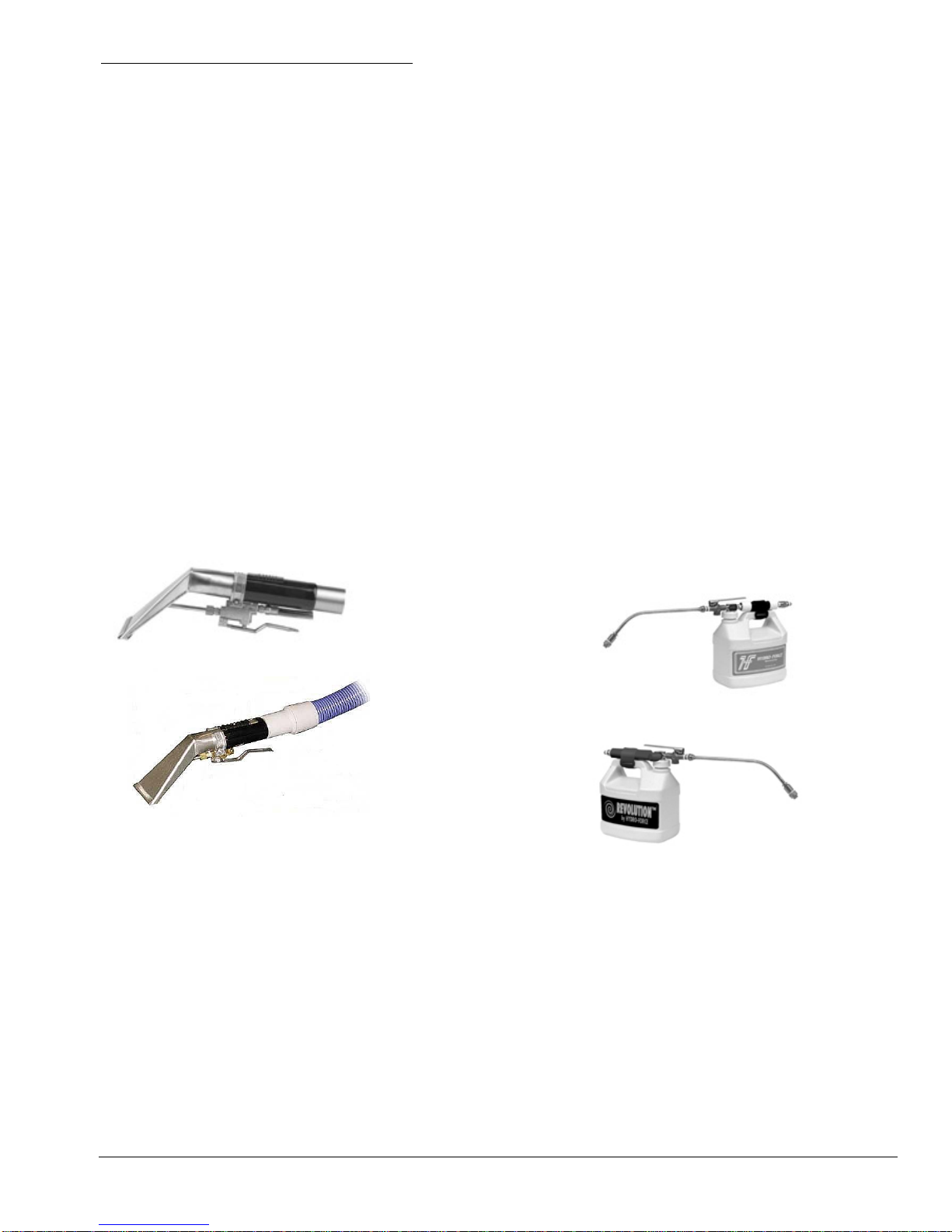
3.5” Hydry Upholstery Tool: AW50A
4.5” Hydry Upholstery Tool: AW51A
3.5” Hydry Deluxe Upholstery Tool: AW50D
4.5” Hydry Deluxe Upholstery Tool: AW51D
1-1/2” Vacuum Hose: (Sold per foot – No cuffs) AH36
2” cuff for 1-1/2” Vac Hose: AH46
1-1/2” cuff for 1-1/2” Vac Hose: AH42
2” Hose Connector PVC: AH76
1-1/2” Hose Connector PVC: AH74
HP Solution Hose: (Does not include Quick Connects) AH79D
1/4” Male Quick Connect: 100009
1/4” Female Quick Connect: 100008
Power Cord 25’ x 12gauge w/male & female plugs AW32
Power Cord 50’ x 12gauge w/male & female plugs AW33
AW50
AW50D
AS12
AS12R
5

Section
1
Safety
CAUTION! This machine is an electrical appliance. Care must be
taken to reduce the risk of electrical shock.
• READ AND UNDERSTAND ALL INSTRUCTIONS BEFORE OPERATING THE M200H.
• To reduce the risk of property damage or injury, repairs to electrical systems should only be performed by
experienced technicians. Contact your distributor for assistance.
• Unplug machine power cord from outlet before performing any repairs on the extractor.
• Plug unit into grounded outlets only. Do not remove ground prong from plug. Use of a Ground Fault
Interrupting (GFI) device will reduce the risk of electrical shock.
• Do not use the M200H outdoors, in standing water or on wet surfaces.
• Do not store the M200 in wet conditions.
• If extractor is leaking, unplug machine power cords from outlets before approaching or touching machine.
• Do not unplug power cord by pulling on the cord. Grasp the plug when unplugging the cord.
• Do not pull the extractor by the cord.
• If cord or plug is damaged, do not use cord. Replace with new cord or repair as needed before use.
• The power cords used must be able to handle an electrical load of 20amps.
• The two power cords must be plugged into separate circuits during operation. Cord #1 must be on 20amp
circuit Cord #2 can be on a 15amp circuit. If the M200H has an Auto Pump-Out system Cord #2 must be on a
20amp circuit. The use of a Breaker Buddy (Hydro-Force part number AX49) will ensure that the two cords are
operating on different circuits (see page 8 for details.)
6

WARNING! This machine must be protected from conditions which may
damage the pump, tank, hoses and other components.
• Freezing of water in this machine will cause serious damage. The M200H, solution hoses, and tools must
be protected from freezing temperature. Store, transport, and use this equipment only in temperatures well
above freezing. (32ºF or 0ºC). If you suspect the M200H has been frozen, do not plug in or turn on machine
until you are sure it has thawed completely.
• If the equipment cannot be stored or transported in a warm environment, it can be guarded from freezing by
running an anti-freeze solution through the incoming water lines, chemical feed system, solution pump, solution
lines, tools and pump-out pump. The machine is filled at the factory with anti-freeze to eliminate damage during
shipment in cold weather.
o The anti-freeze solution must be completely flushed from the machine before it is returned to service.
• The M200H must not be used to pick up flammable or combustible materials or used in areas where these
materials may be present.
• Solvent-based or water-based solutions containing solvents may damage the pump, hoses, and other
components. Do not assume chemical compatibility. Contact your distributor or Hydro-Force if you have
questions regarding the compatibility of your chemicals with the machine.
• Do not clean with solutions in the tank that are at temperatures above 140ºF. Turn pump ON and prime pump
before turning heater ON.
• Rinse the solution tank, chemical system, and pump with fresh water after each day’s use.
• Do not allow pump to run dry. Always maintain adequate solution level to supply solution pump.
• HP hoses may rupture if worn or damaged. Do not use HP solution hoses if hose covering is cut, bulging, or
otherwise damaged. Examine HP solution hoses daily and replace or repair hoses as needed.
• Rinse tank and store the M200H with the recovery tank lid open. With Auto-Pump-out Option - Use a Hydro-
Filter and clean the recovery tank daily to keep pump-out pump from becoming clogged.
• Keep Vacuum Inlet Filter clean and check float ball for proper operation. Do not operate the M200H without
the Vacuum Inlet Filter in place. Use defoamer to eliminate foam build-up during cleaning and prevent
foam/moisture from entering vacuums.
***Use common sense to protect yourself and others while using this equipment.***
• Keep pets and children away from the machine when in use.
• Keep all body parts, hair, and loose clothing away from openings and moving parts. Always wear appropriate
clothing and safety equipment when operating unit.
• Use extra care when cleaning on stairs. Wet carpet on stairs can be slippery.
• Do not move the M200H up or down stairs when tanks are full of water. Drain solution and recovery tanks
before moving unit up or down stairs. Lift using only the appropriate handles.
• Water may be spilled, drip, or be exhausted from vacuums during operation. Place unit in area where water will
not cause damage or use drop cloth to protect surfaces.
7
Section
2
Operation Procedures
Knowledge of the proper operation of the M200H is required to ensure user
safety and efficient performance of the extractor.
SET UP AND OPERATION
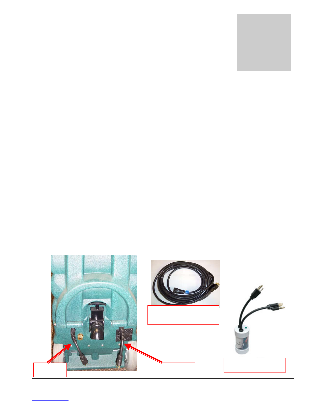
1. Electrical Cords:
Two 25’ power cords are supplied with the Olympus M200H. The power draw requires that the Cord #1 be
plugged into a 20amp circuit. Cord #2 can be on a 15amp circuit, unless the M200H has an Auto Pump-Out
system, if it is used, then Cord #2 must be on a 20amp circuit.
Plug the two power cords into two outlets from different circuits.
If you are not sure if you are connected to separate circuits, use a Breaker Buddy (item # AX49), available
from Hydro-Force, to test your circuits in the following manner:
• Plug the cords into the two outlets being tested, and then plug the Breaker Buddy into the two cords.
• If the green indicator light fails to light, you may be on the same circuit and must select a different
plug for one of the cords.
• If the green indicator light comes on, you are plugged into two different circuits; connect the cords to
the machine and proceed with your set-up procedure.
If a circuit breaker trips during operation, reset the breaker and move the cord to another outlet as needed.
Power Cord – AX32
25’ – 12 gauge M-F Plugs
Cord #2 Cord #1
8
Breaker Buddy – AX49
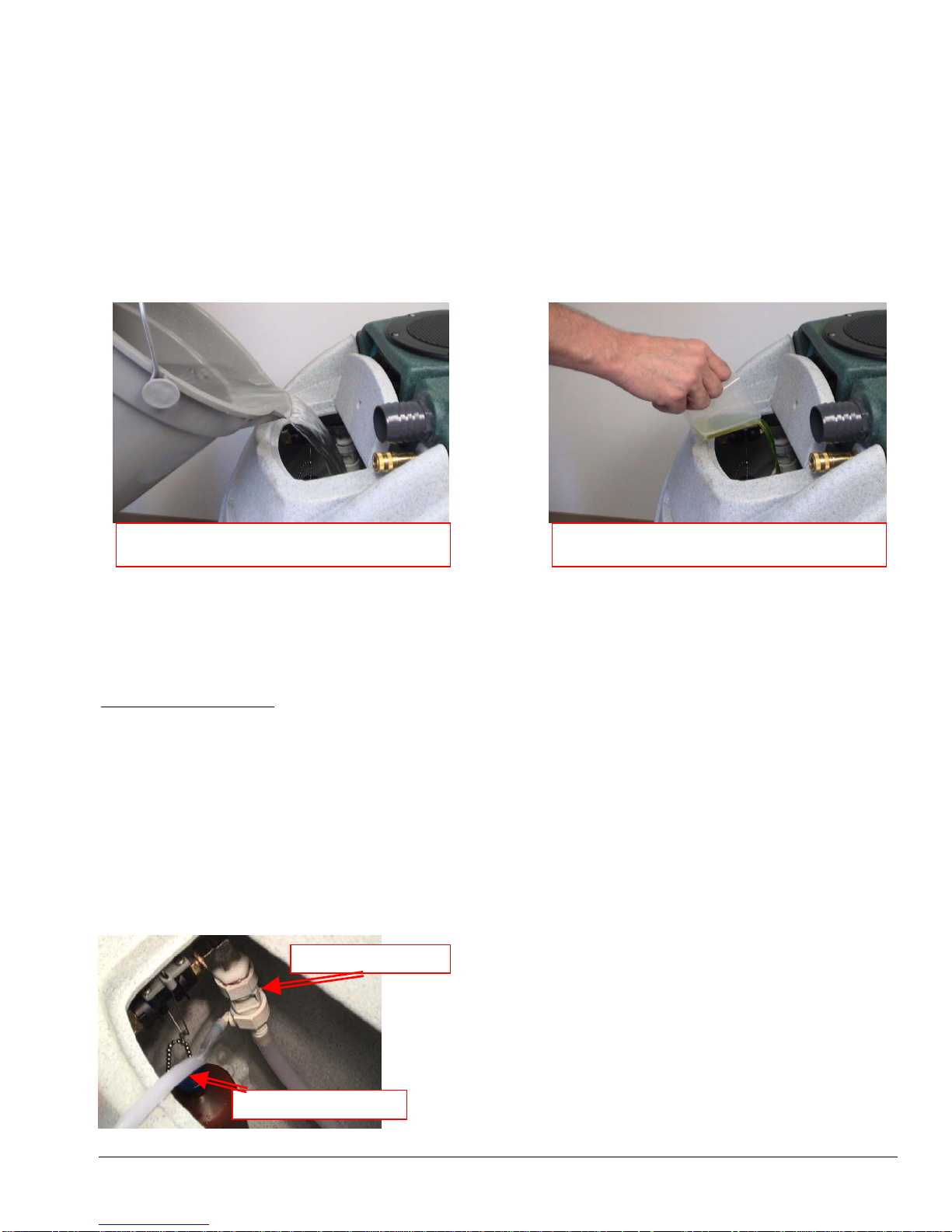
2A. Water Supply & Chemical Mixing– Manual Fill:
• Pour up to 12 gallons of hot water into the solution tank at the front of the machine. The water
temperature in the tank cannot exceed 140°F.
• Measure and add the appropriate amount of the desired liquid chemical to the water in the solution tank.
The amount of chemical will vary depending on the type of chemical used, the amount of water in the
tank, and the material being cleaned; consult the chemical packaging for specific mixture ratios.
• Powdered chemicals should be dissolved in water before adding to the water in the solution tank.
DO NOT RUN OUT OF WATER WHILE USING THE MACHINE! Ensure that the tank
contains enough water to complete each job. If the water level is low: stop cleaning, turn off the
pump, and refill the tank. Running the pump dry will damage the pump and void the warranty.
Pour appropriate amount of hot water into
Add appropriate amount of chemical to water
2B. Water Supply & Chemical Dilution – Optional Auto-Fill System:
• The chemical dilution rate is controlled by the metering tip, and the dilution rate can only be changed by
changing the metering tip (See “How to Change the Metering Tip” on Page 10 for instructions.)
Chemical Feed Setup:
• Remove the chemical feed hose from the solution tank.
• Place the end of the hose into a container of liquid chemical.
• If the tip is removed, and the proportioning system operated with no tip, the dilution rate will be 8:1 (the
equivalent to adding 16-1/4oz of chemical to each gallon of water.)
• The standard tip used with the M200H is the turquoise tip with a dilution rate of 256:1. This means that
for each gallon of water flowing into the machine, 1/2 ounce of chemical will be added.
• If a fresh water rinse with no chemical is desired, simply leave the chemical feed hose inside the
solution tank.
Proportioning Valve
Chemical Feed Hose
9
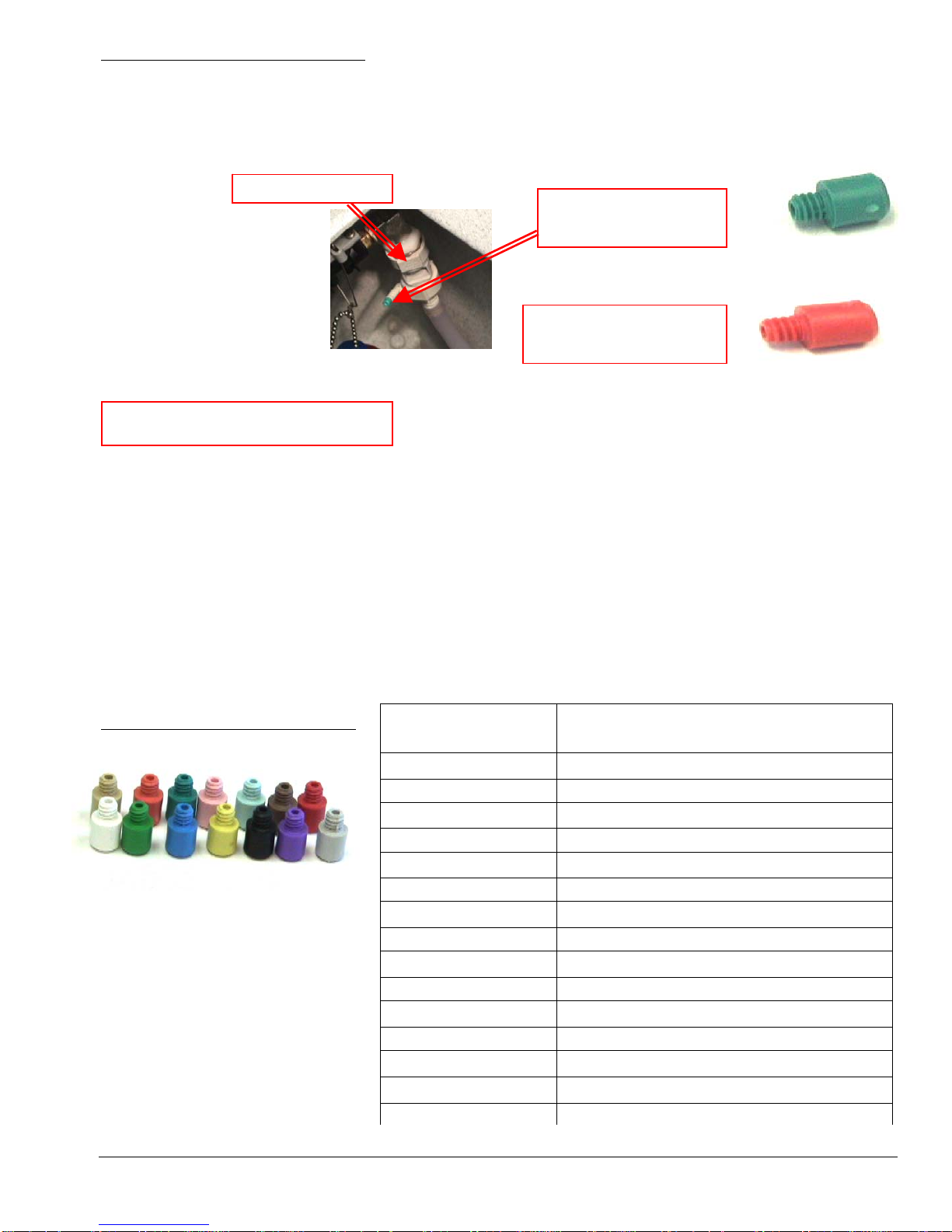
How to Change the Metering Tip:
• Remove the chemical feed hose from the barb on the side of the proportioning valve.
• Unscrew and remove the old tip.
• Screw in the proper tip for your chemical tip and place the hose back on the barb
Proportioning Valve
Turquoise Tip
Dilution 256 - 1
Red Tip
Dilution 85 - 1
Metering Tip Kit – PDE001
Metering Tip Kit (Hydro-Force Item# PDE001) contains 14 different colored metering tips, allowing
dilution rates from 11:1 up to 427:1. Refer to the chart below to select the tip that meets the dilution rate for
your chemical application.
• For example: if you require 1-1/2 ounces of chemical per gallon of water, change to the red metering tip
with the dilution rate of 85:1.
• The dilution rates are based on chemicals with water-like viscosity. Thicker (more viscous) chemicals will
dilute at a different rate.
• For powdered chemicals, a liquid concentrate must be made. Mix the concentrate according to the
manufacturer’s directions, and then select the appropriate metering tip.
• Contact your distributor or Hydro-Force if you have questions about your chemical.
Metering Tip Application Chart:
TIP
COLOR
CHEMICAL DILUTION RATES
OZ / GAL (RATIO)
TAN 0.30 (427:1)
ORANGE 0.40 (320:1)
TURQUOISE 0.50 (256:1)
PINK 0.75 (170:1)
LIGHT BLUE 1.00 (128:1)
BROWN 1.12 (114:1)
RED 1.50 (85:1)
WHITE 1.75 (73:1)
GREEN 2.00 (64:1)
BLUE 2.50 (51:1)
YELLOW 3.75 (34:1)
BLACK 5.00 (26:1)
PURPLE 8.50 (15:1)
GRAY 11.50 (11:1)
NO TIP 16.25 (8:1)
10
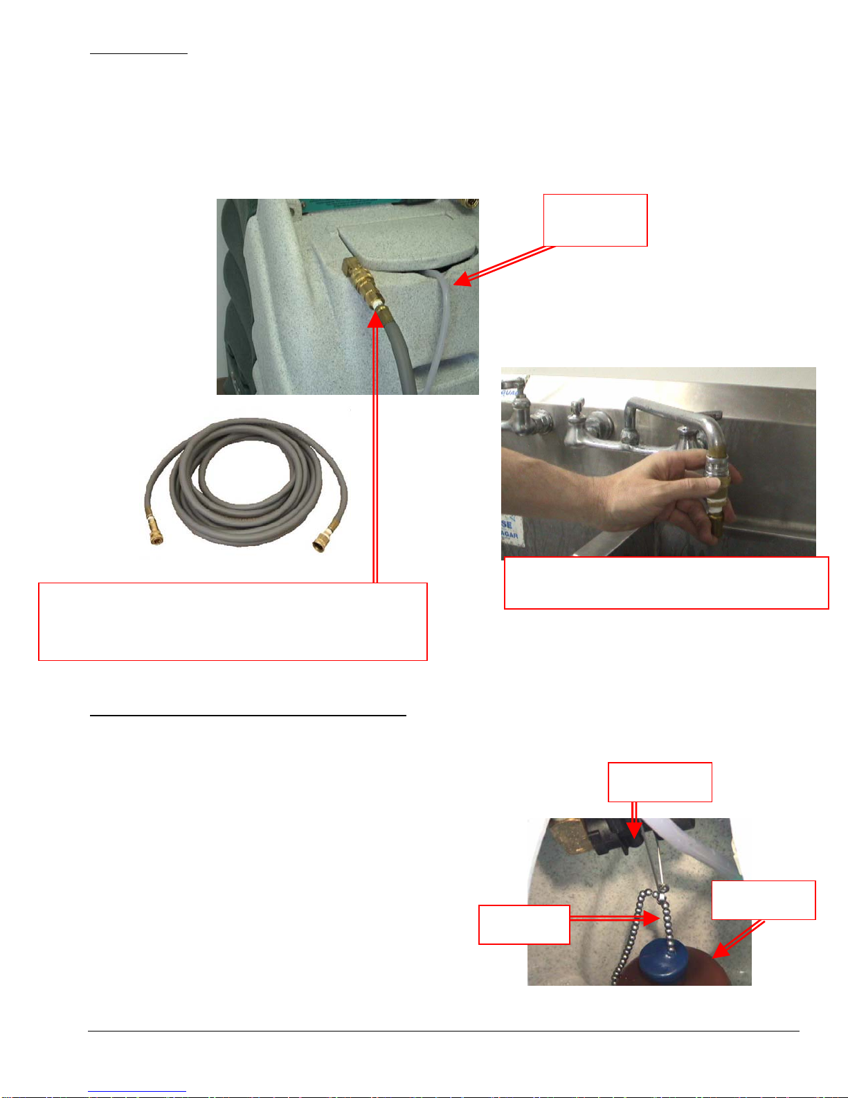
Water Supply:
• Once the correct metering tip is in place:
o Connect the Auto-Fill Water Supply Hose to the water inlet (the male quick-connect on the front
of the machine.)
o Connect the other end of the hose to a water faucet, and then turn on the water.
• Hot water can be used as long as the temperature does not exceed 140°F.
• Faucet adapter kits (Hydro-Force item #AX21 & AX22) are available that allow connection to different
types of faucets if needed.
Chemical
Feed Hose
Connect the Auto-Fill Water Supply Hose to Solution Inlet
(Male quick connect on the front of the machine.)
3/8” id X 25’ with F Quick Connect & F Garden Hose Fitting
Connect the Auto-Fill Water Supply Hose to a
faucet and turn on the water
To adjust the water level in the solution tank:
• Turn off the water supply.
• Adjust the length of the chain connecting the float bottle to the float valve.
• Snap the beaded chain off the connector on the valve.
Float Valve
o Move the bottle down to decrease the water level.
o Move the bottle up to increase the water level.
• Snap the chain back into the connector.
• Turn the water supply back on.
If the chemical is not drawing, or if the tank is not filling
or is overflowing, refer to the trouble shooting guide, or
contact your distributor for assistance.
Chain
Float Bottle
11
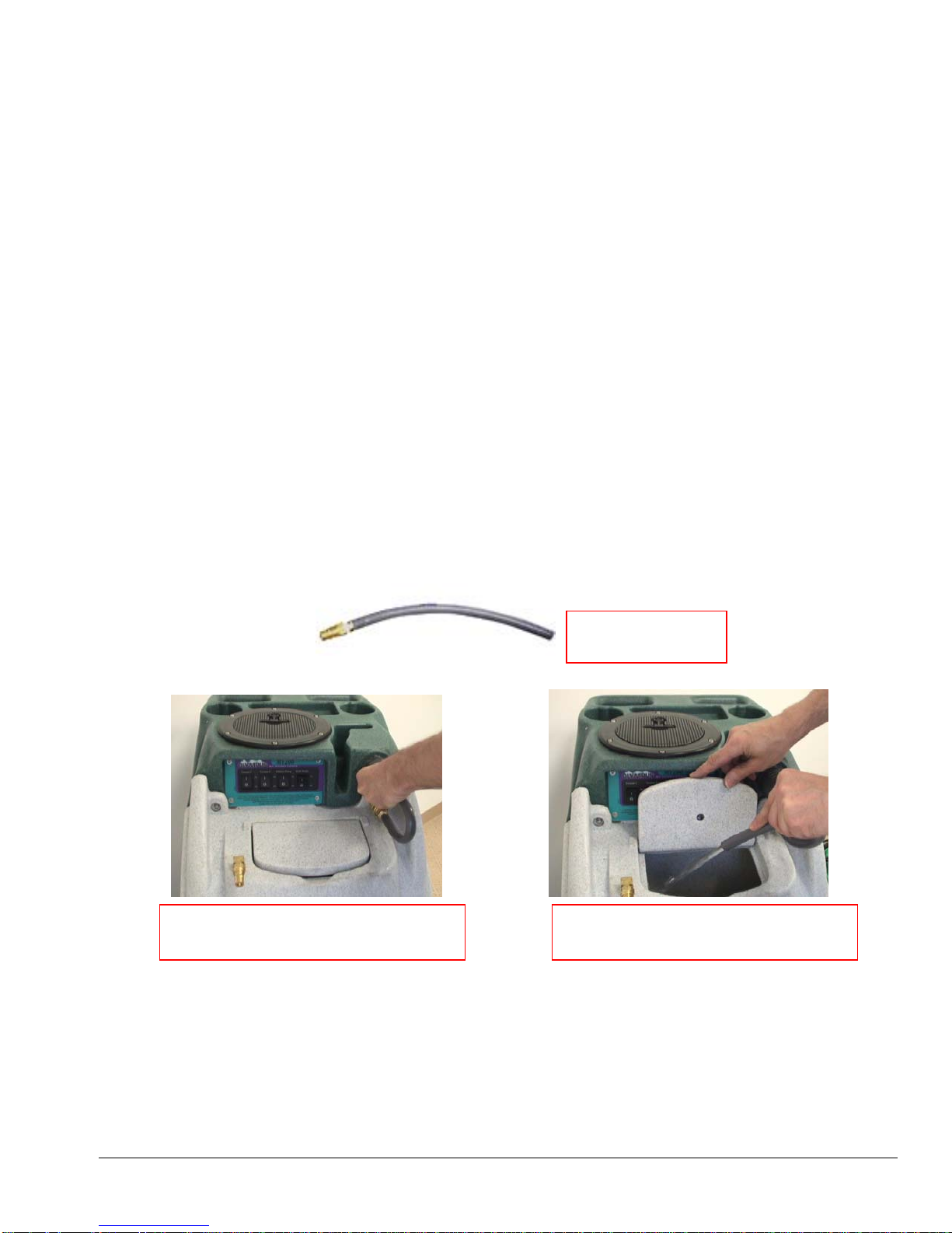
3. Priming the High-Pressure Pump:
Once water is in the solution tank, the high-pressure solution pump must be primed:
• Connect the short prime hose to the solution outlet (female quick-connect on the front of the
machine.)
• Direct the end of the hose back into the solution tank and turn the solution pump switch to the ON
position.
• When a steady stream of water is flowing out of the hose, turn off the solution pump, remove the
hose, and proceed with the set-up procedures.
If the pump does not prime quickly, the vacuum may be used to aid priming:
• Direct the end of the short prime hose into the vacuum barb on the front of the machine.
• Turn on one or both of the vacuum motors
• Turn on the solution pump.
• Cup a hand around the hose & barb to increase the vacuum suction on the hose.
• When water is flowing out of the hose, direct the hose to the solution tank and turn off the vacuum
motors to ensure the flow continues when the vacuum is removed.
• When the flow is steady, turn off the solution pump, remove the hose, and proceed with machine set-
up procedures.
If the pump still does not prime, or if flow is low or unsteady, check the hose from the solution tank to the
pump (as well as the inline filter) for clogging, kinks, or restrictions. Clean or replace hose and/or filter and
repeat the priming procedure.
If you are having trouble with the pump, refer to the trouble shooting guide or contact your distributor for
advice or assistance.
Pump Prime Hose
NM5080
Place end of prime hose and use
vacuum to prime the solution pump.
Keep prime hose connected and run
pump until flow is strong and steady
12
4. Connection of Solution Hose:
Connect the high pressure solution hose to the solution outlet (female quick connect on the front of the
machine). Connect the other end of the hose to the male quick connect on the cleaning tool. When you are
ready to start cleaning, turn the solution pump switch to the ON position
HP Solution Hose Assembly – AH79D
1/4” id X 25’ with M-F Quick Connects
Connect the male end of the HP Solution Hose
Assembly to the female solution outlet fitting on
the machine. Connect the female end to the
cleaning tool.
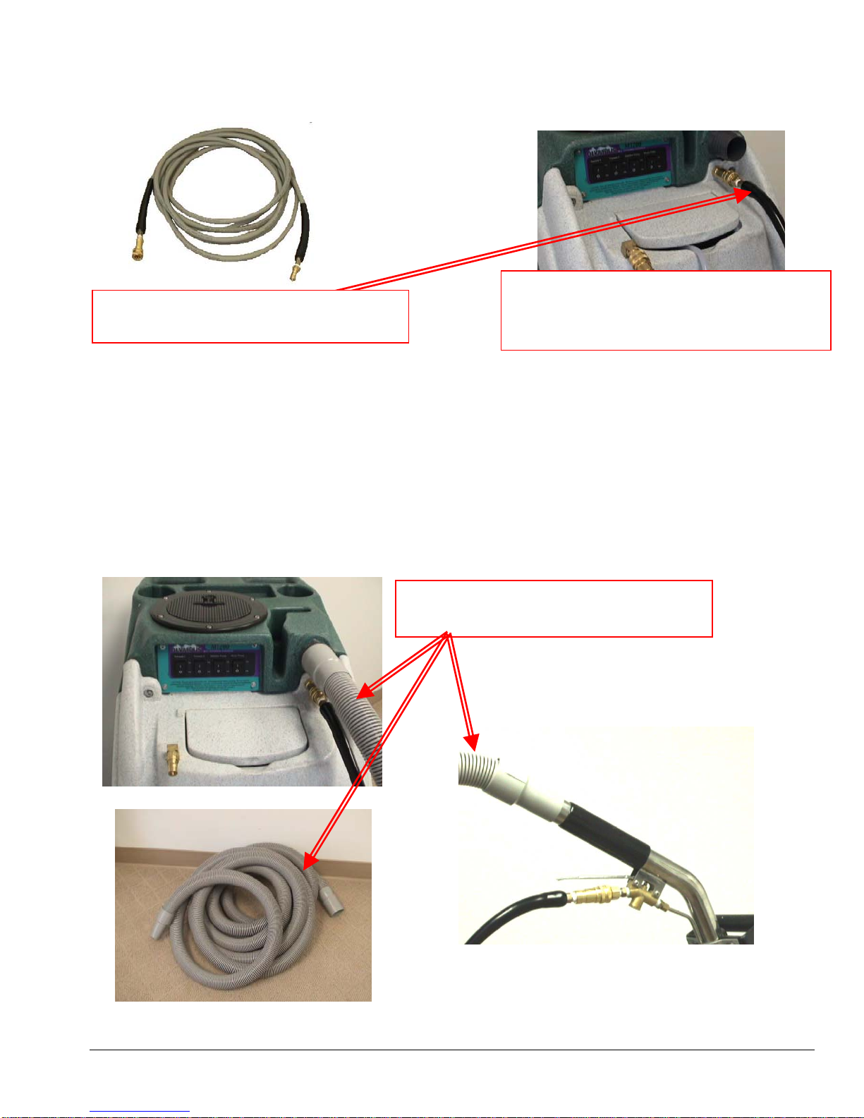
5. Connection of Vacuum Hoses:
A 1-1/2” x 25’ Vacuum Hose is included with the M200H. The 2” cuff on the 25’ vacuum hose is connected
to the Vacuum Barb on the front of the machine. The other end with the 1-1/2” cuff is connected to the
cleaning tool.
When ready to begin cleaning, turn both vacuum switches to the ON position. While the M200H can be
operated with only one vacuum for cleaning delicate fabrics, in most situations you will turn both vacuum
switches ON.
Vacuum Hose
1-1/2” x 25’ with 2” & 1-1/2” cuffs
13
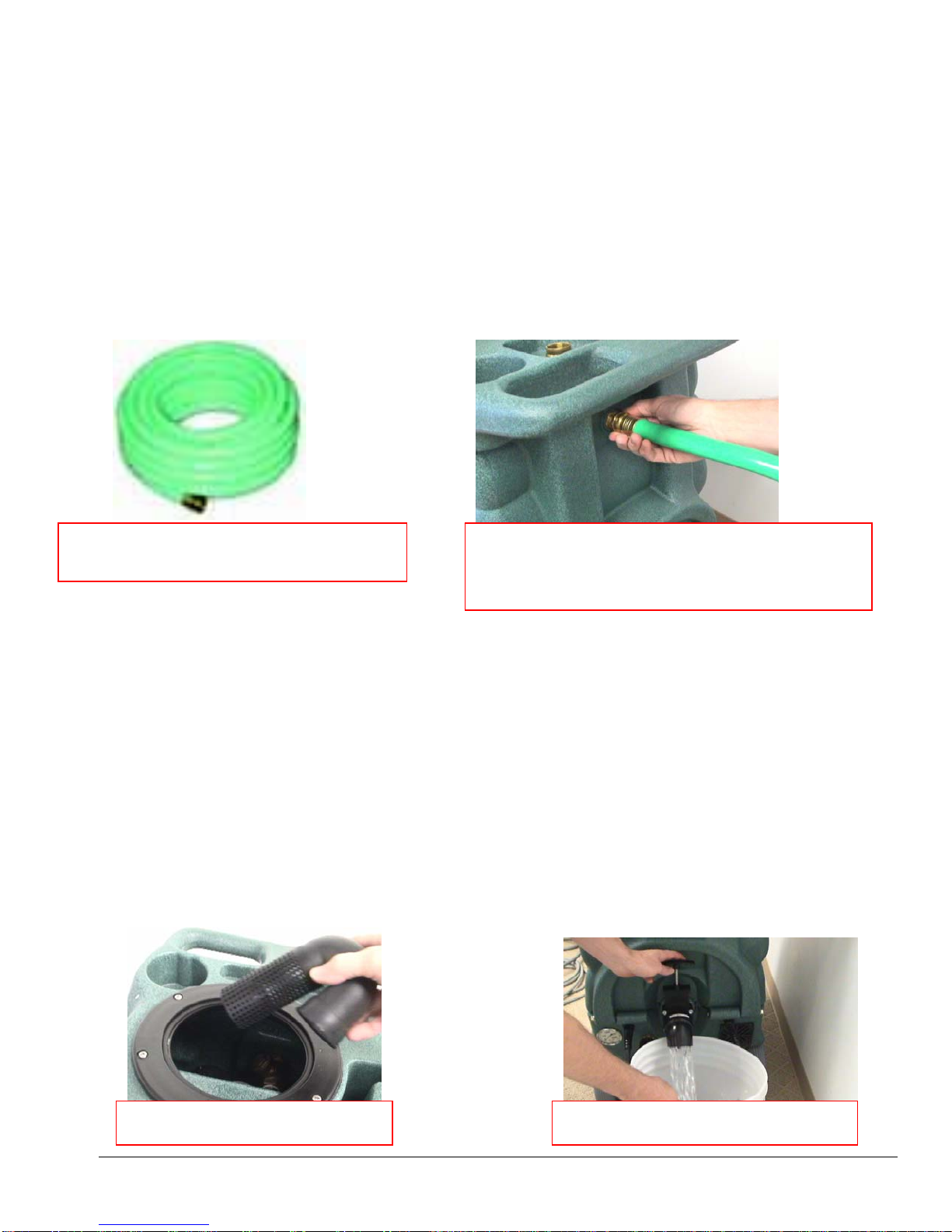
6. Optional Auto Pump-out System - Connection of Pump-out Hose:
The pump-out hose is a 50’ section of 3/4” garden hose.
• Remove the cap from the pump-out outlet fitting on the back of the machine.
• Connect the pump-out hose to the outlet fitting.
• Place the other end of the hose in a commode or drain connected to the sanitary sewer system.
• Secure hose end to prevent movement during pumping.
Use defoamer to prevent foam build-up in recovery tank during cleaning and to keep foam/moisture
from entering vacuums.
When ready to begin cleaning, turn the waste pump switch to the ON position.
• Do not turn on waste pump switch unless pump-out hose is connected and has been routed
to a proper drain.
Pump-out Hose – AH65
3/4” id X 50’ with M-F Garden Hose Fittings
Connect the Female Garden Hose Fitting end of the
Pump-out Hose to the outlet fitting on the back of the
recovery tank. Place the other end of the pump-out
hose in a sanitary drain.
6A. Waste Tank Shutoff:
If not equipped with an Auto Pump-out System or not using the waste pump-out, the pump-out hose does
not need to be connected. When the recovery tank fills during cleaning, the float ball assembly in the vacuum
inlet filter will rise and will automatically shut off the vacuum air flow to prevent the recovery tank from
overfilling and waste water from getting into the vacuums. When this occurs:
• Immediately shut off the vacuum switches.
• Drain the recovery tank.
o Turn off the pump switch while draining the tank.
o Turn pump switch back upon resumption of cleaning.
• Close the drain valve and turn the vacuum switches back on when ready to resume cleaning.
If the pump-out or vacuum shutoff is not working properly, refer to the trouble shooting guide or contact
your distributor for advice or assistance.
Float Shutoff Assembly – NM5037
14
Draining the Recovery Tank

7. Pressure Adjustment:
The pressure regulator of the M200H is not adjustable. It is preset at the maximum pressure setting of
200psi; however, the highest pressure attained is dependent on the amount of water flow at the tool. The
maximum flow rate to maintain 200psi is 0.67gpm. This means to maintain 200psi the largest jet size is for a
single jet tool is 03 or two 015 jets on a dual jet cleaning wand.
• Smaller jets and lower flow will allow for higher pressure at the tool.
• Larger jets and higher flow will lower the maximum pressure attained at the tool.
The number found on the face of the jet, such as 8003, 95015 or 11004, states the size and shape of the jet
orifice. The first two or in some cases three numbers (80, 95 & 110) represent the spray angle. The last two or
in some cases three numbers (03, 015 & 04) represent the orifice size. The orifice size number represents the
flow through that jet at 40psi in tenths of a gallon per minute. Thus a small orifice such as 015 will flow
0.15gpm at 40psi. A larger orifice such as 04 will flow 0.40gpm at 40psi. (See chart below.)
Different jets with the same spray angle (8001, 8003 & 8004) can have different orifice sizes.
Different jets with the same orifice size (80015, 95015 & 110015) can have different spray angles.
Choose the jets that will meet the flow rate at your desired pressure and have the spray pattern suited to your
tool and type of cleaning.
If maintaining pressure becomes a problem, refer to the trouble shooting guide or contact your distributor for
advice or assistance.
Tee Jets and Vee Jets
Equiv. Dia. Flow Capacity (Gallons Per Minute)
Orifice Size in inches 40psi 60psi 100psi
01 0.026 0.10 0.12 0.16
015 0.031 0.15 0.18 0.24 0.34 0.41 0.53 0.75
02 0.036 0.20 0.25 0.32 0.45 0.55 0.71 1.00
03 0.043 0.30 0.37 0.47 0.67 0.82 1.10 1.50
04 0.052 0.40 0.49 0.63 0.89 1.10 1.40 2.00
05 0.057 0.50 0.61 0.79 1.10 1.40 1.80 2.50
06 0.062 0.60 0.73 0.95 1.30 1.60 2.10 3.00
08 0.72 0.80 0.98 1.30 1.80 2.20 2.80 4.00
10 5/64 1.00 1.20 1.60 2.20 2.70 3.50 5.00
15 3/32 1.50 1.80 2.40 3.40 4.10 5.30 7.50
200psi 300psi 500psi 1000psi
0.22 0.27 0.35 0.50
To determine the flow rate of tools with multiple jets, add the flow of each jet together to calculate the total
flow at the desired pressure.
15
 Loading...