

Page 1
OLYMPUS
1
RESEARCH
MlCROSCOPES
SERIES
BH2
REPAIR
(BHS)
MANUAL
Page 2
TO
OLYMPUS MICROSCOPE SERVICING PERSONNEL
This manual has been published chiefly for proviciing repair procedures for the OLYMPUS System Microscope BHS, but
internal construction of the main body. However, light sources of these models are different and specifically described in "Troubleshooting" contained in the
The Series BH2 models feature
of the Series BH, except for
BH2-BIITR tubes are of the constant tube length design and are different in the internal mechanism from
BH-BIITR, though optical alignment procedures for the prisms are nearly the same. Further, adoption
of the constant tube length design has made it possible
inserted into the right side eyepiece sleeve of the
adjust parfocality of observation tube and phototube.
In order to prevent trouble from occurring during
parts are fixed with cement and are particularly
Removing procedures are given for parts which are
ing force.
Prisms are glued with Araldite
cement with
be disassembled even after removing excessive cement, heat the entire area of the cemented surface with
a soldering iron or a similar tool.
In the descriptions contained in this manual, "right" and "left" are defined in the direction as seen by the
microscopist sitting in the observing position through the microscope.
For cleaning lenses, a liquid mixture of alcohol
should be made to "How to Clean the Microscope" which
is
applicable also to the Models BHT and BHTU which are similar to the Model BHS in the
last
part of this manual.
a
fine & coarse adjustment assembly of essentially the same design as that
a
reduction gear unit which
OT1028. When
a
razor blade (one-side edge) or knife edge before attempting disassembly. If the prisms cannot
it
is
attached to the rear of the arm in Series BH2.
lo
take lnicrographs with the focusing eyepiece
observatio~i lube, illereby introducing the necessity to
shipmelit or long-term use, importants immovable
descrit~ed at the steps of disassembly in this manual.
glued with adhesive agents of exceptionally high bond-
is
necessary to disassemble these prisms, cut off excessive
(3)
and ether
is
(7)
should be used. For details, reference
available upon separate request.
Requisites for repairs:
1.
First of all, ascertain what parts of the microscope the user or owner of which wishes you to repair.
2. Never fail to check the entire function of the microscope before you commence
a) Find out what parts are defective and how much they are
b) Prior to
efficient way.
3.
After completing the repair, check the functions of not only the re-assembled parts but also the entire
microscope to make sure no defect should be left unremedied.
4.
Be careful not to deform repair parts during the assembly, make
fied for purpose.
5.
Make repairs promptly and accurately.
repair, think of the best possible order to disassembling the defective parts in
damaged.
it
practice to use tools and jigs speci-
its
repair.
a
most
Page 3
CONTENTS
1 . REPAIR TOOLS AND JIGS
.
EXPLODED PARTS DIAGRAMS
2
.
DISASSEMBLY PROCEDURE FOR FlNE
3
COARSE ADJUSTMENT UNIT OF BHS
4
.
ASSEMBLY PROCEDURE FOR FlNE
COARSE ADJUSTMENT UNIT OF BHS
.
DISASSEMBLY PROCEDURE FOR BASE UNIT
5
.
6 ASSEMBLY PROCEDURE FOR BASE UNIT 42
.
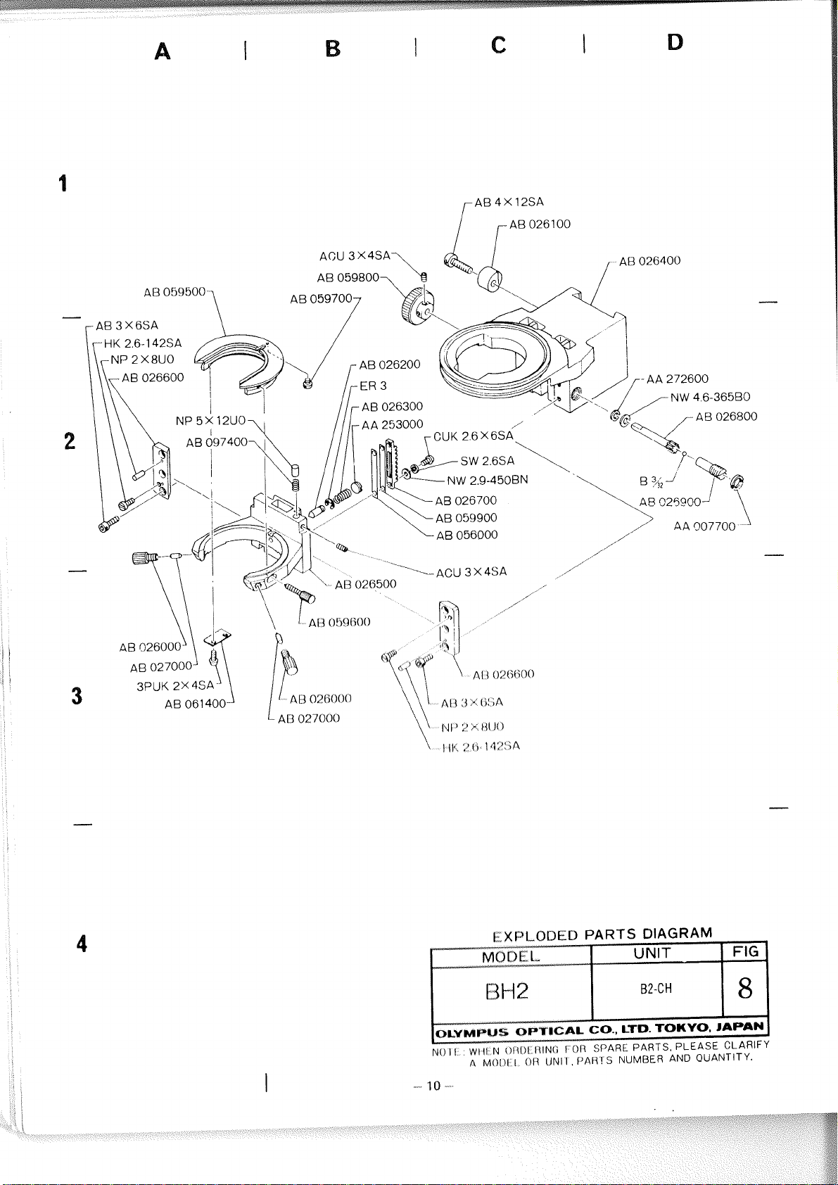
7 DISASSEMBLY PROCEDURE FOR BIi2.CH 44
.
8 ASSEMBLY PROCEDURE FOR BH2 ..CH.. 46
.
OVERALL ASSEMBLY AND ADJUSTMENT FOR BHS-F
9
.
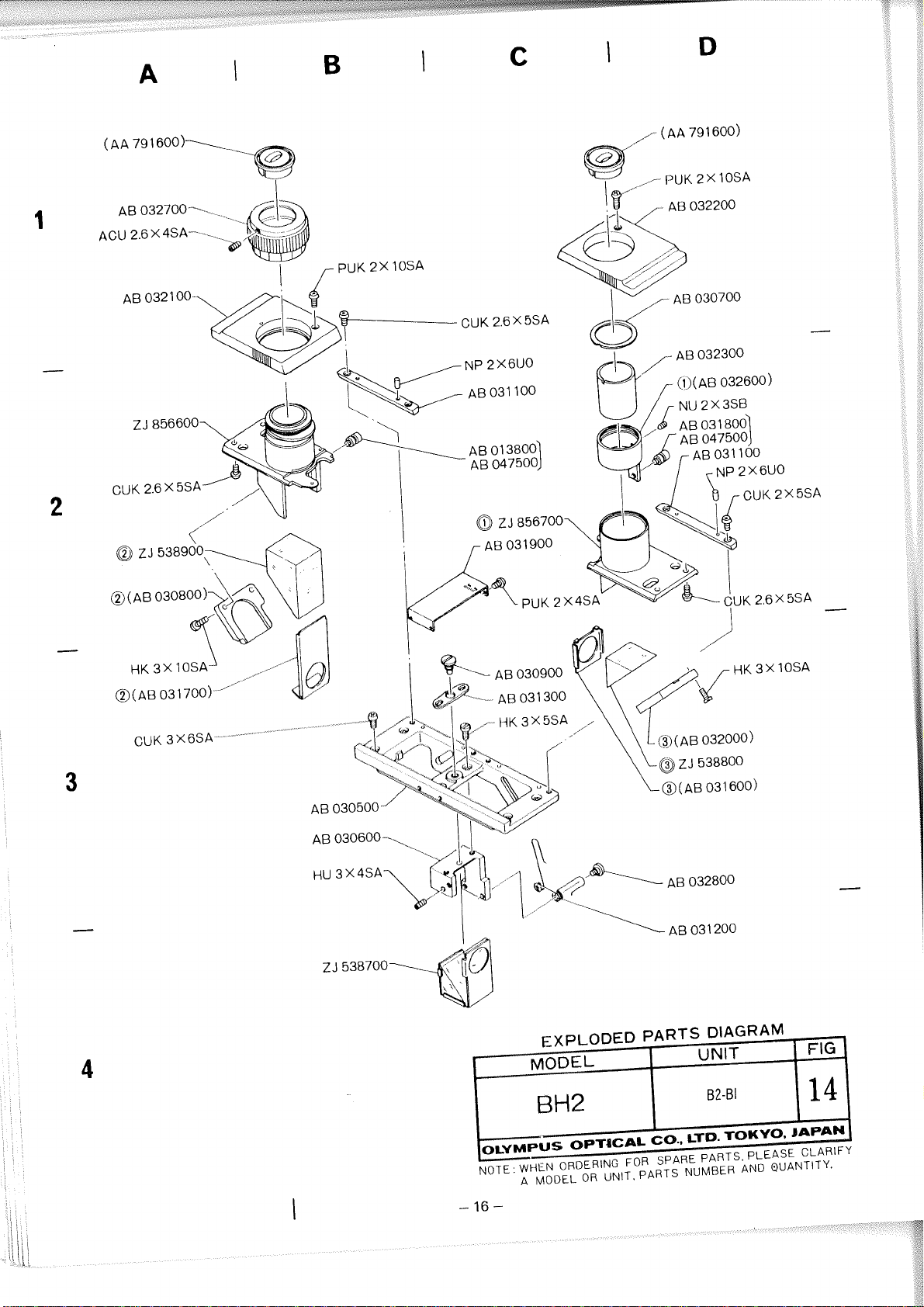
10 DISASSEMBLY PROCEDURE FOR BH2.BI
.
11 ASSEMBLY PROCEDURE FOR BH2.BI 57
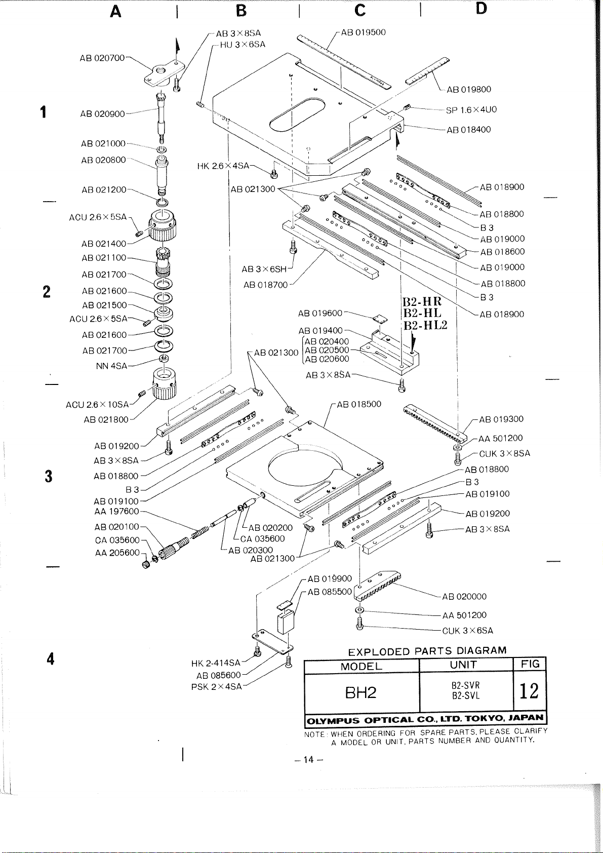
12
.
DISASSEMBLY PROCEDURE FOR BH2.TR
.
ASSEMBLY PROCEDURE FOR BH2.TR
13
14
.
DISASSEMBLY PROCEDURE FOR BH2.SV
............................................
........................................
&
..................................
&
..................................
...........................
1
3
21
29
40
..............................
...............................
................................
...................
................................
48
52
...................................
...............................
..................................
...............................
67
69
75
.
ASSEMBLY PROCEDURE FOR BH2.SV
15
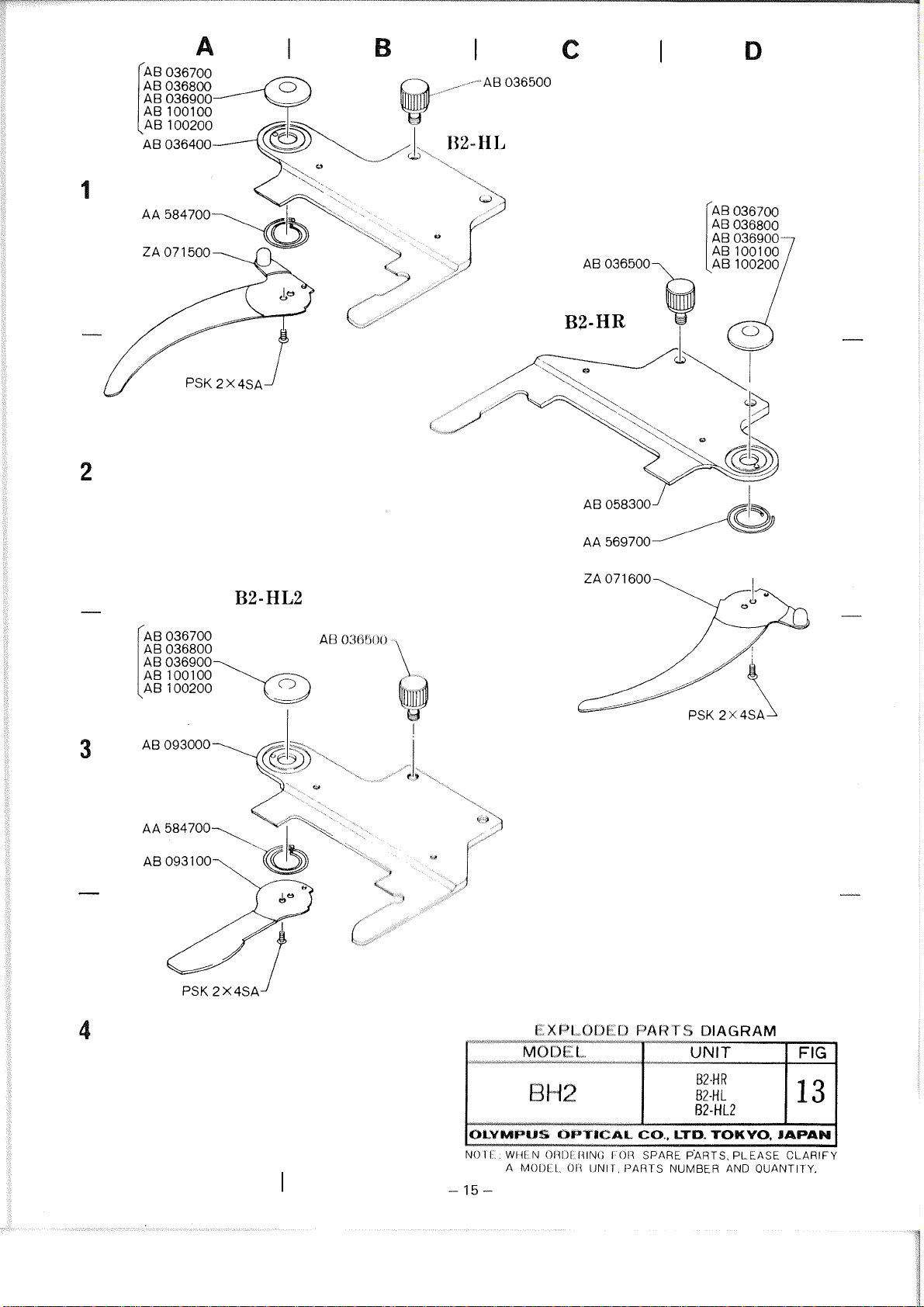
16 . DISASSEMBLY AND ASSEMBLY PROCEDURE FOR BH2.HRIHL 89
17
.
DISASSEMBLY PROCEDURE FOR BH2.AAC
.
ASSEMBLY PROCEDURE FOR BH2.AAC
18
.
DISASSEMBLY AND ASSEMBLY PROCEDURE FOR BH2.CD..
19
.
TROUBLESHOOTING OF ELECTRICAL SYSTEM
20
.
ELECTRIC CIRCUIT DIAGRAM
21
........................................
..................................
81
............
..............................
.................................
.............
..........................
90
92
94
95
97
Page 4
1.
REPAIR TOOLS AND GREASE
1-1
Regular Tools
1-2
OTOOl
I
OT0015
OT0016
OT0018
OT0022
OT0023
OT0035
OT0079
OT0207
OT02 16
OT0309
OT0317
OT1027
OT1028
OT1126
OT1131
OT1141
OT1144
Grease
OT2006
OT2008
OT2012
Set of screwdrivers (6 pcs.)
Phillips screwdriver (medium size)
Phillips screwdriver (large size)
Screwdriver (large size)
Adjustable spanner (flat tip)
Handle of small size Phillips screwdriver, using
Tweezers (special made)
Pliers
Allen wrench (width 2.5
mm)
Set of Allen wrenches (8 pcs.)
Tension gauge
Thickness guage
Alon Alpha (adhesive)
Araldite (adhesive)
Bellock (adhesive)
Shellac (20
Phillips screwdriver tip, using
g) (adhesive)
OT0023
Tension gauge
OT1 141
1-3
Special Tools
OX Eyepiece with cross hair
1
Focusing magnifier (PM-FT-36)
Pin face wrench for tension adjustment nut
AA007700
Pin face wrench for nut of stage
Pin face wrench for fine adjustment
Tool for holding gear
Test plate for observation tube alignment
(1/100 square)
Centering objective for optical alignment of observation tube (for 160
Standard objective for optical tube length alignment
Centering objective for optical alignment of observation tube (for 200
Special WF 10X for optical tube length alignment
Special centering telescope
Stnadard jig for mechanical tube length control
Jig for receptacle balls
Spoon for balls
mm)
mm)
Page 5
Pin tiole tube for aligning optical axis of mirror
Centering adapter
Positionitiy jig for rack AB024100
Block for cliccl<iny sensitivity of fine adjustment
Block for cliccking sensitivity of fine adjustment
Jig for
UIITR tulle prism alignment of BH2 series
Alignment jig
IJosilionilig jig for prism ZA071000 of BH2-TR
.Jig fol intcrljupillary distance
at
62 mm of BH2-BIITR
Aligri~r~etit jig for photo tube of BH2-TR
Finder
eyepiccc
Page 6
I
A MODEL OR UNIT. PARTS NUMBER AND QUANTITY.
-3-
Page 7
L7:::8500/ KNW 3SA
/
AB
0866007,
3
X
AB 034700
AB 023400
AB 024800
105A
Al
j
0:3?
AA 001
PI
100
A13
033800
II<
-
t100
3X/l(;,
/
-
I
"
Uv
/
\
V'
AA 782900
PUK 2x6s.
AB 034800
--
A13
AB 4 X
6SA
PUK 2 X 4SA
AU 0!19000
AB 059200
AB
3X6SA
3PUK 2 6 X 4SA7 TAB 060700
'$w@~
russuu-
CA 035600
EXPLODED PARTS
OLVMPUS OPTICAL
WtfL
N
01~1)~
A
MOIH
I
lilbi(i
011
O~JI
,
----
1
014
I
C,Ul,
'~I'AfiI
IIAII
,,r
11
1%
1~~it4
I
ct
rd11t
t1i1
CSK 2 6 X 6%
DIAGIIAM
Pl%i&'lTC'r.
.-
*&
I
lsl
I
A'JI
ti
~trit)
OlJAN I I1
JAP
(:I
ARIF
Y.
Y
Page 8
CSK
2.6
X
6SA
EXPLODED PARTS DIAGRAM
I
NOTE: WHEN ORDERING FOR SPARE PARTS. PLEASE CLARIFY
-5-
MODEL
A MODEL OR UNIT. PARTS NUMBER AND QUANTITY.
I
UNIT
1
FIG
I
Page 9
A
M0I)I I OIi UNIT. PARTS NUMBER AND OUANTITY.
Page 10
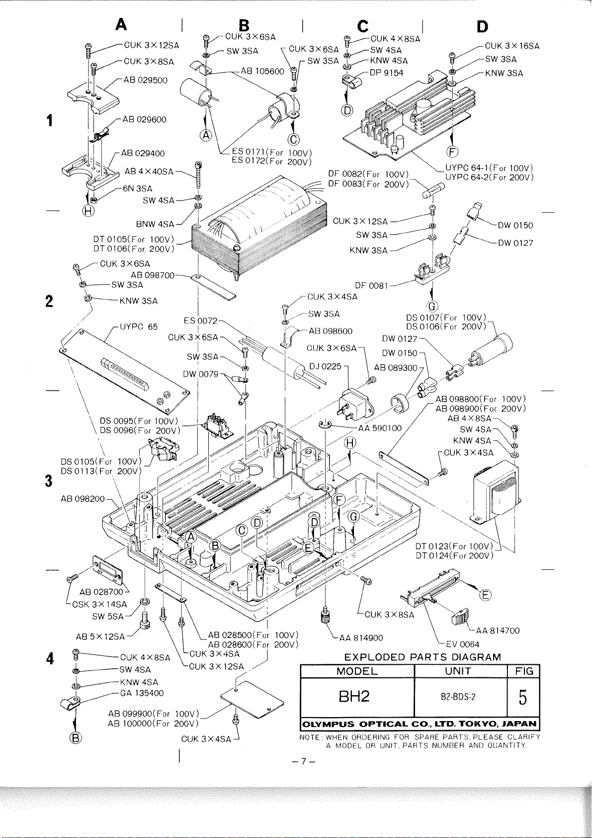
DT 0105(For 100V)
DT 01 06(For 200V)
UYPC 64-1 (For 100V)
UYPC 64-2(For 200V)
-CUK 3X4SA
AB 099900( For 100V)
CUK 3 X 4SA
I
'AA 8 14700
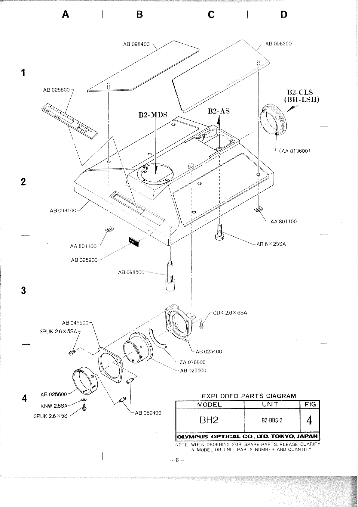
EXPLODED PARTS DIAGRAM
MODEL
B2-BDS-2
OLYMPUS OPTICAL CO., LTD. TOKYO, JAPAN
I"
NOTE. WHEN ORDERING FOR SPARE PARTS. PLEASE CLARIFY
- 7 -
h40DEL OR UNIT. PARTS NUMBER AND QUANTITY.
A
Page 11
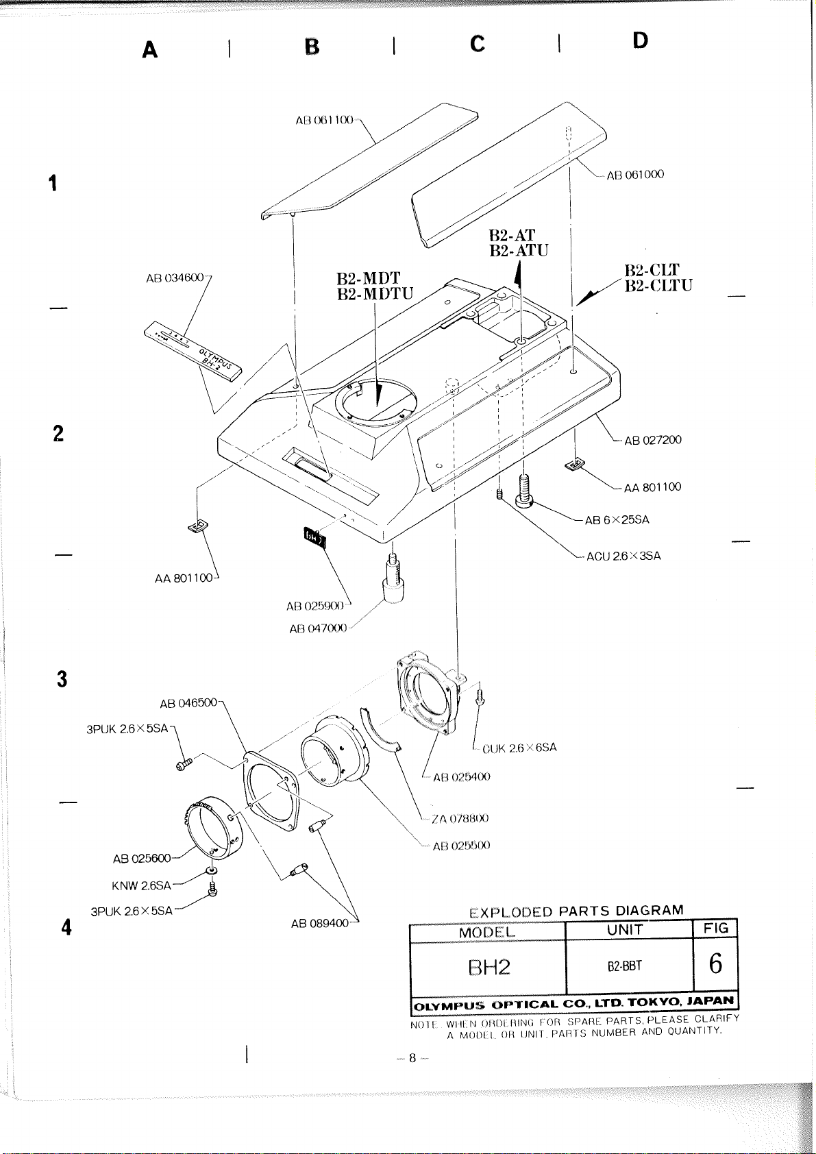
AB
A9 025600
KNW 2.6SA
3PUK 2.6 Y 5SA
046500
,*
\
A[
1
O;'!?!)lH)
Page 12
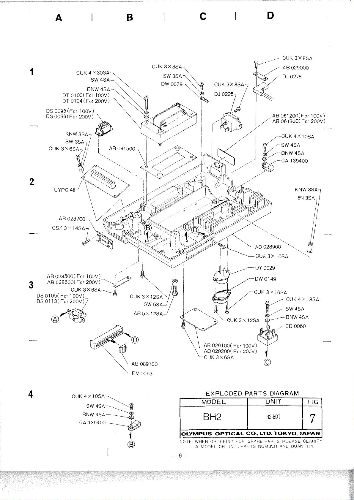
CUK 4 x 30SA
DT
0103(For 100V)
DT 01 04 (For 200V
)
DS 0095 (For 100V
DS 0096 (For 200V)
AB 028500( For 100V)
AB 028600( For 200V)
)
'
AB 061 200(For IOOV)
AB 061 300( For 200V)
-
4
CUK 4X lOSA,,,
BNW 4SA
GA 135400
CLJK 4' 18SA
EXPLODED PARTS DIAGRAM
NOTE WHEN ORDERING FOR SPARE PARTS PLEASE CLARIFY
A MODEL OR UNIT. PARTS NUMBER 4ND QUANTITY.
Page 13
Page 14
Page 15
LA 459400.1
CUK
2.6 X 25SA
I
'
-
----
LA 459600
AB 058500
O&---
2;
7;;:;;
AA 726300
1
fY3\
A% 022400
1
NO1 I WIII N OI\I)I IIING FOR SPARE PARTS. PLEASE CLARIFY
A
MOIII-
I.
ON
UNIT, PARTS NUMBER AND QUANTITY.
--
1
2
-
-
Page 16
A
I
CUK
2.6 X 30SA
B
I
C
096200 AB 060200-
I
D
CUK
3 X 8SA
-
EXPLODED PARTS DIAGRAM
MODEL
I
OLYMPUS OPTICAL CO.. LTD. TOKYO, JAPAN
NOTE. WHEN ORDERING FOR SPARE PARTS. PLEASE CLARIFY
A MODEL OR UNIT. PARTS NUMBER AND QUANTITY.
1
I
UNIT
I
1
I
FIG
Page 17
AB 021 000
AB 021200---.
.--
-
I
---
---SP
1.6X4U0
---
AB 0 1 8400
-
..
ACU 2.6
-
X
1
OSA
Page 18
PSK
2
x
~SA'
-
"%M*d4d--
L
XPL
061LAX3
PSK
2
TS
DIAGRAM
x
4~~1
I
0I.VMPIJS
NO]
I
-
15
-
OfJTICAL
WI{L
N
OITIII
A MOl)l 1 01i ON11 PARTS NUMBER AND OUANTITY.
I~ING
I
o1i
CQ.,
SPARE
LTD. TOKYO,
P'ARTS
PLEASE
JAPAN
CLARIFY
Page 19
Page 20
EXPLODED PARTS DIAGRAM
NO1
E:
WHEN ORDERING FOR SPARE PARTS. PLEASE CLARIFY
A MODEL OR UNIT. PARTS NUMBER AND
OiJANTITY.
Page 21
AA 788900~
AB 034200---
CUK
3X8SA
__
ER
AND
QUANTITY.
Page 22
AB 040800
PUK
2
X
EXPLODED PARTS DIAGRAM
6SA
OLVMPUS OPTICAL CO., LTD. TOKVO
NOTE WHEN ORDERING
A MODEL OR UNIT. PARTS NUMBER AND QUANTITY.
FOH
SPARE PARTS. PLEASE CLARIFY
JAPAN
Page 23
[
EXPLODED
MODEL
PARTS
I
DIAGRAM
UNIT
I
I
FIG
I
OLVMPUS OPTICAL CO.. LTD. TOKYO. JAPAN
NnTF
WHFN
..".
-,
ORDERING FOR SPARE PARTS. PLEASE CLARIFY
.. .-
.
-
A MODEL
OR
UNIT, PARTS NUMBER AND QUANTITY.
I
Page 24
D
3.
DISASSEMBLY PROCEDURE FOR FINE & COARSE ADJUST3MQ&T OF
BHS
-
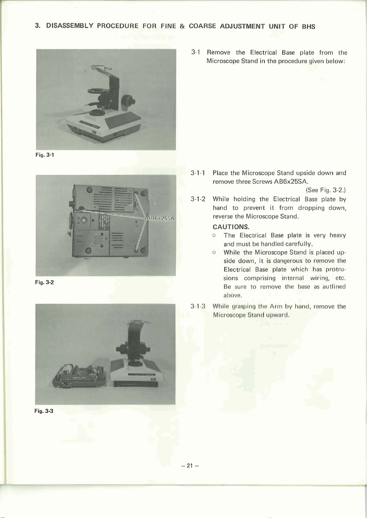
3-1 Remove the Electrical Base plate from the
Microscope Stand in the procedure given below:
Fig.
3-1
3-1-1 Place the Microscope Stand upside down and
remove three Screws
3-1-2 While holding the Electrical Base plate
hand to prevent
AB6x25SA.
(See Fig.
it
from dropping down,
3-2.)
by
reverse the Microscope Stand.
Fig.
3-2
I
3-19
CAUTIONS.
o
The Electrical Base plate
is
very heavy
and must be handled carefully.
o
While the Microscope Stand is placed up-
it
is
side down,
dangerous to remove the
Electrical Base plate which has protru-
sions comprising internal wiring, etc.
Be sure to remove the base as autlined
abova.
Whllr
Mlcro8cop~
grr~plng tha
Bund
upward.
Arm
by
hand, remove the
Fig.
3-3
-21
-
Page 25
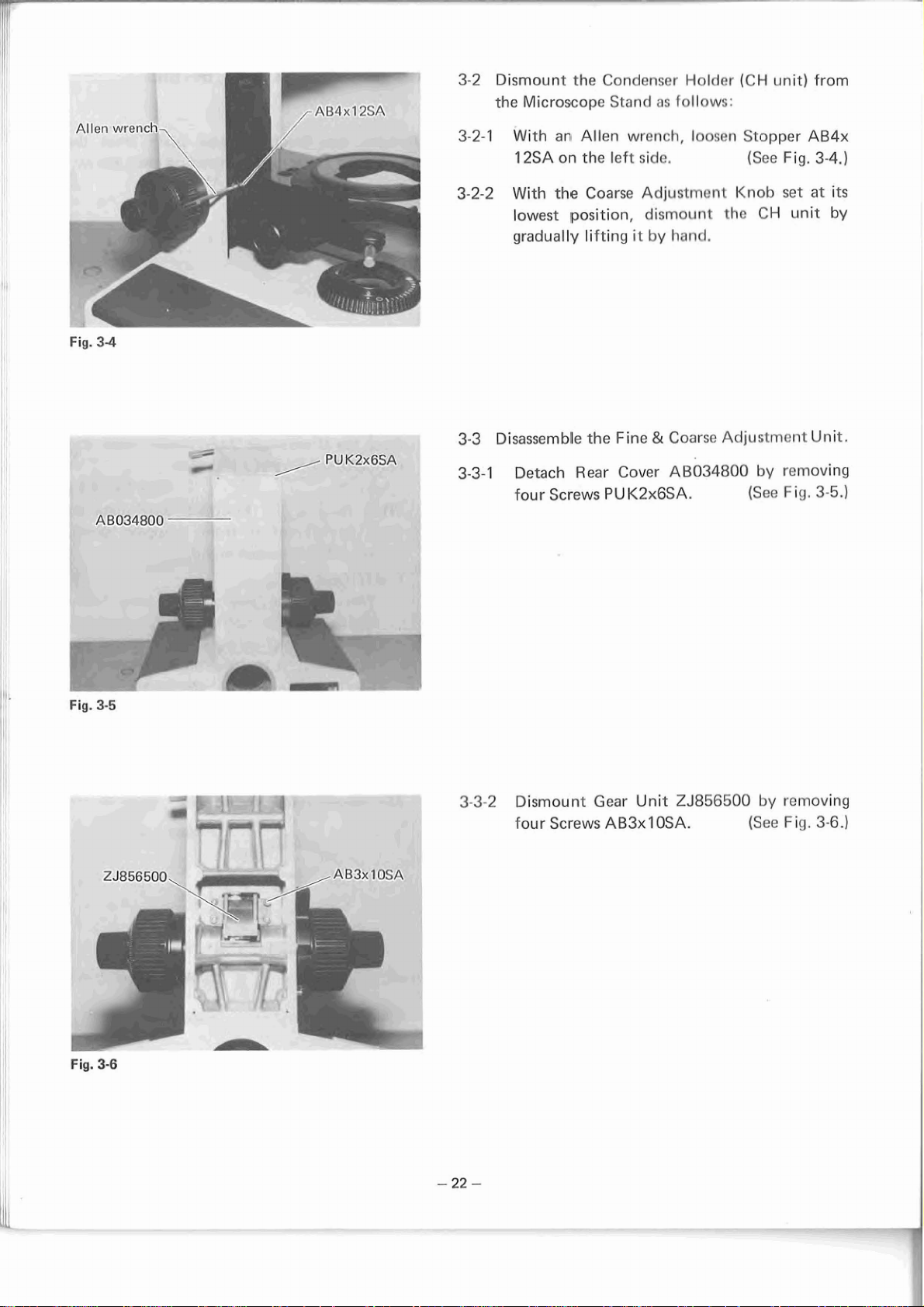
3-2
Dismount
the
Microscope
the
Condenser
Stand
Holder
as
follows:
{CH
unit)
from
Fig.
34
4
/
-
PU
K2x6SA
3-2-1
3-2-2
3-3
Disassemble
3-3-1
With
an,
Allen
12SA
on
the
left
With
the
Coarse
lowest
gradually lifting
Detach
four
position,
the
Rear
Screws
fine
Cover
PUK2x6SA.
wrench,
side.
Adjustrncnt
dismount
it
by
hand.
&
Coarse
loosen
~~034800
Stopper
(See
Knob
the
CH
Adjustment Unit.
by
(See
AB4x
Fig.
3-4.)
set
at
its
unit
by
removing
Fig.
3-5.)
Fig.
Fig,
3-5
3-6
h-
c.
3.3-2
~C.7
YE-
',-+:
-
4
7
,
>-'
"~1.-
w
Dismount
four
Screws
Gear
AB3xl
Unit
OSA.
ZJ856500
by
(See
removing
Fig.
3-6.)
Page 26
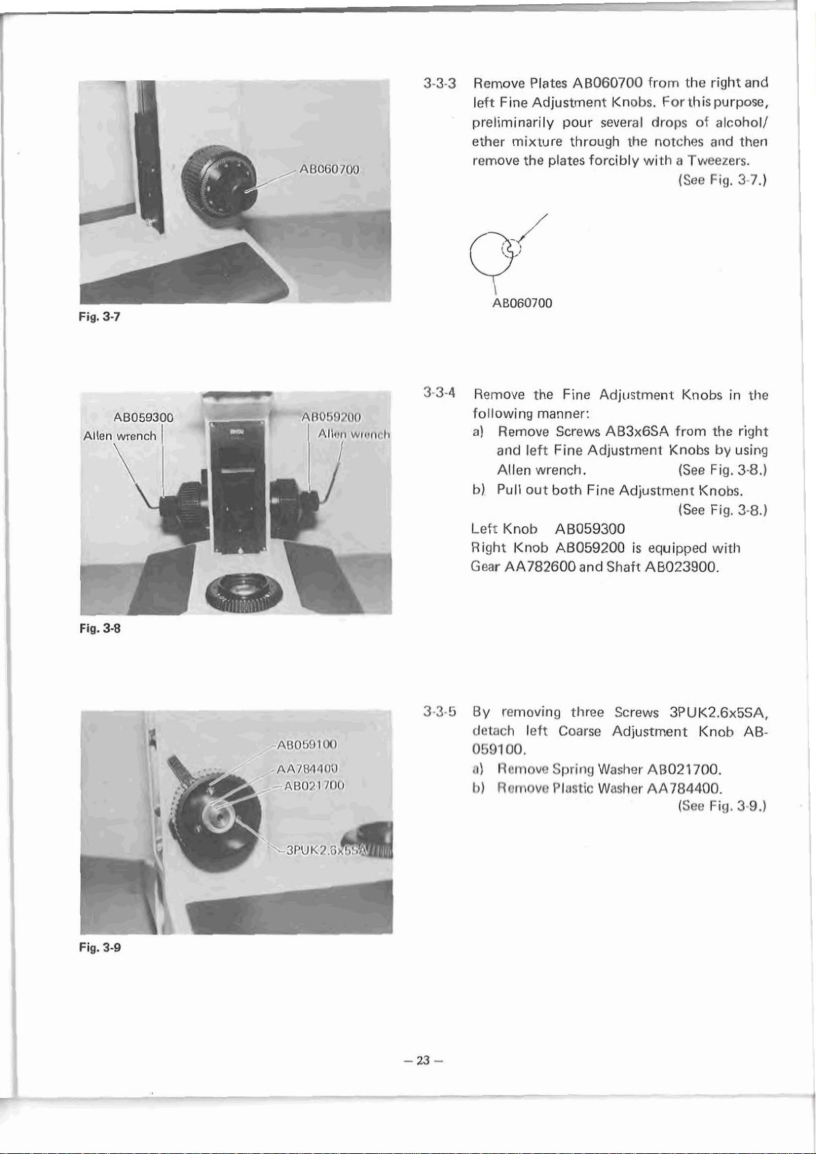
Fig.
3-7
3-3-3
preliminarily
ether
remove
a,,
.-.
'#
~not;n/oo
I
_.
Remove
left Fine Adjustment
Plates
mixture
the
plates forcibly
AB060700
pour
through
Knobs.
several
the
from
For
drops
notches
with
a
(See
the
right
this
purpose,
of
alcohol/
and
Tweezers.
Fig.
and
then
3.7.)
Allen
It
I
Fig.
AB059300
wrench
\
3-8
I
n
4
-
[)n1~o1o~~
4rl11!1
7
1
/[lo
3-34
3-3-5
Remove
following
a)
Remove
and
Allen
bJ
Pull
Left
Knob
Right
Gear
By
detach
0591
n)
1))
Knob
AA782600
removing
00.
Rt!movo
nnrnovr!
the
Fine
manner:
Screws
lef~
Fine
wrench.
out
both
AB059300
A8059200
left
Coarse
Spring
Plastic
Adjustment
AB3xGSA
Adjustment
Fine Adjustment
is
equipped
and
Shaft
A8023900.
three
Screws
Adjustment
Washer
Washer
AB021700.
AA784400.
Knobs
from
Knobs
(See
(See
3PUK2.6x5SA.
(See
in
the
by
using
Fig
.3-8
Knobs.
Fig.
with
Knob
Fig.
the
right
,)
3-8.)
AB-
3-9.)
I
I
3l
>L
Page 27

Fig.
3-1
3-36
./---
-
1
0
0T02Q3
Prepare
to
AA872200
ACU3x5SA.
detach
after
Fine
Drive
loosening
Shaft
two
(See
Fig.
Mount
Screws
3-1
0.)
Fig.
3-1
3-3-7
While holding
remove
tu.rning
it
the
Fine
the
right
Adjustment Knob
counterclockwise.
Drive
Shaft
(See
Fig.
Mount,
by
3-1
1
.)
NOTE:
For
I
holding
rubber sheet
1
3-3-8
Remove
the
or
Spring
Fine
Drive
pliers.
AA784200.
Shaft
(See
Mount,
Fig.
use
3-1
a
2.)
Fig.
3-1
!
2
Page 28
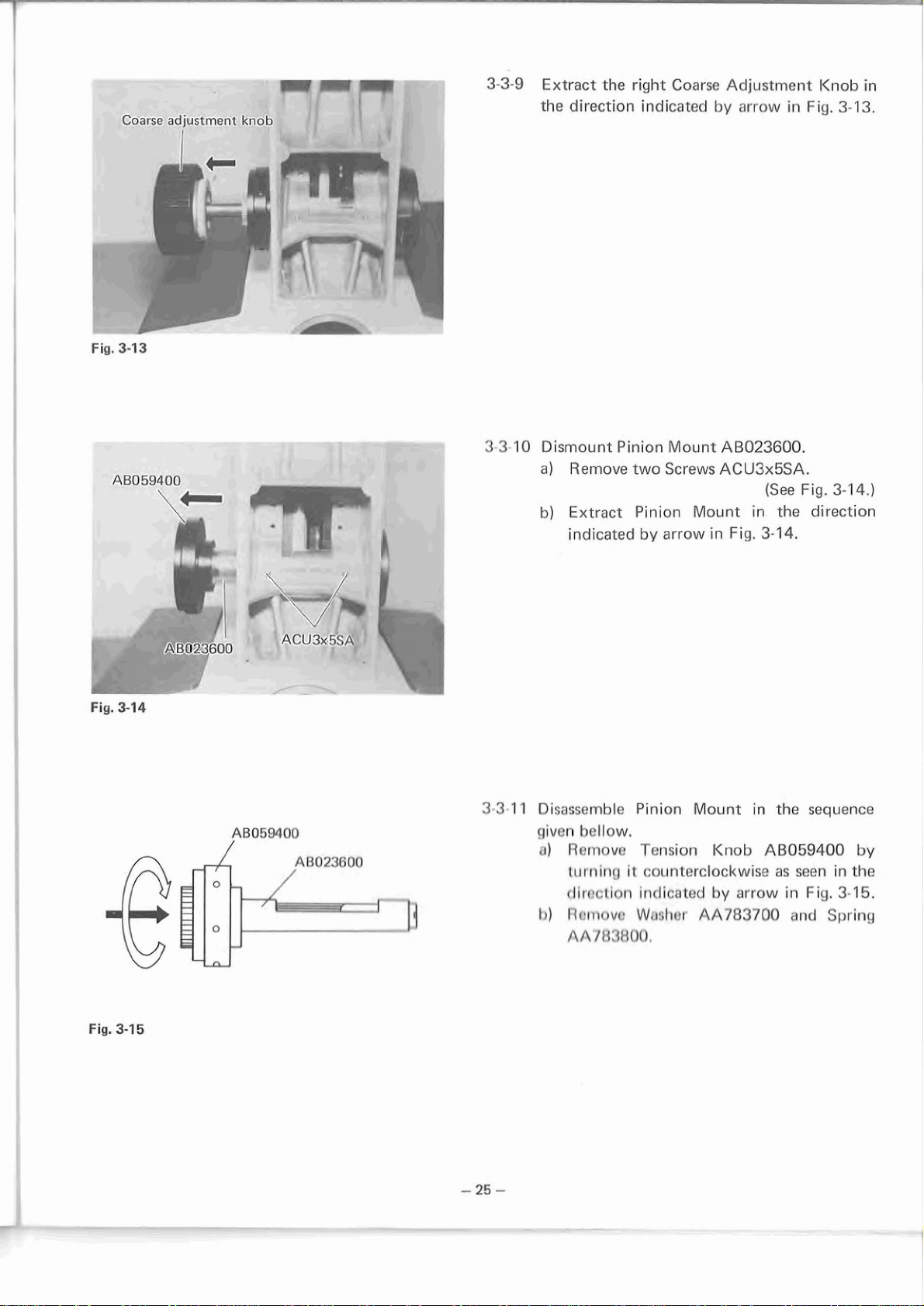
Fig.
Coarse
3-13
adjustment
I
'.-
-'
-
-
-
3-3-9
3-3-1
Extract
the
0
Dismount
a)
b)
the
direction
Pinion
Remove
Extract
indicated
right
Coarse
indicated
Mount
two
Screws
Pinion
by
arrow
Adjustment
by
arrow
AB023600.
ACU3x5SA.
Mount
in
in
Fig.
in
(See
the
3-14.
Knob
Fig.
3-1
Fig.
3-1
direction
in
3.
4.1
Fig.
Fig.
3-14
3-15
AB0591.00
1
3.3
11
Disassemble
given
n)
1))
Pinion
bellow.
Remove
turning
rlirrr:tion
Rcqrnnvr
AA7tt3ftO0,
Tension
it
counterclockwise
indicated
Wlrnhrr
Mount
AA783700
Knob
hy
arrow
in
AB059400
the
as
in
and
seen
Fig.
sequence
by
in
the
3-15.
Spring
Page 29
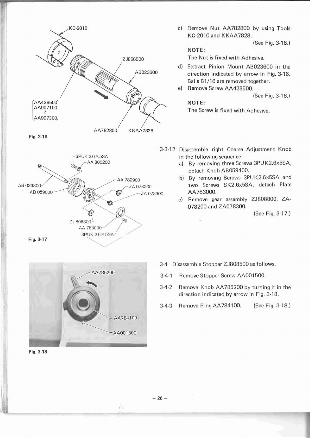
c)
Remove
NOTE:
The
d)
Extract
direction
Balls
el
NOTE:
Tbe
KC-2010
Nut
B1/16
R
ernove
Screw
Screw
Nut
AA782800
and
KKAA7828.
is
fixed
with
Pinion
Mount
indicated
are
removed
AA428500.
is
fixed
Adhesive.
AB023600
by
arrow
together.
with
Adhesive.
by
{See
in
(See
using
Fig.
Fig.
Fig.
Tools
3-
f
6.)
in
the
3-16.
3-16.)
Fig.
3-76
3PUK
~~782800'
2.6
X
5SA
K
~~~7828
3-3-1
2
Disassemble
in
the
following
a)
By
removing
detach
b)
By
removing Screws
two
Screws
right
Coarse
sequence:
three
Screws
Knob AB059400.
3PUK2.6x5SA
S
K2.6x5SA,
Adjustment
3PU
K2.6x5SA,
detach
Knob
and
Plate
AA783000.
c)
Remove
078200
I
!
Fig.
3-17
3.4
Disassemble
3m4.1
Remove
gear
and
2
Stopper
Stopper
assembly
A078300.
ZJ808500
Screw
AAOOl
23808800,
(See
Fig,
as
follows.
500.
3-1
ZA-
7.)
Fig.
3-18
fr
$rn
---\
-'-/
\;
!
AA784100
3-4-2
3-43
Remove
direction
Remove
Knob
AA785200
indicated
R
ing
AA784100.
by
arrow
by
turning
in
(See
Fig.
it
3-18,
Fig.
in
3-1
the
8.)
Page 30
-
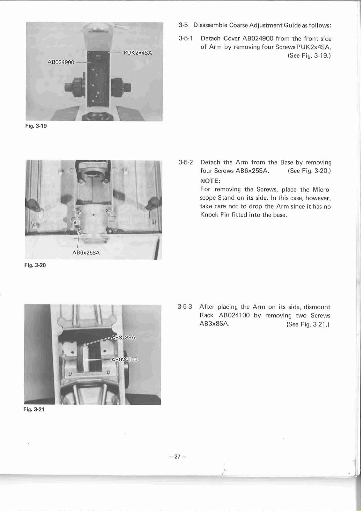
3-5
Disassemble
Coarse
Adjustment
Guide
as
follows:
Fig.
AB024900
3-19
--
p-r
PU
K2x4bu
.-
3-5-1
3-5-2
Detach
of
Detach the
four
NOTE:
For
scope
take
Knock
Cover
Arm
Screws
removing the Screws,
Stand
care
Pin
AB024900
by
removing
Arm from
AB6x25SA.
on
not
to
fitted
its
drop
into
four
side.
the
the
In
the
from
Screws
(See
Base
(See
place
this
Arm
base.
the
P
U
Fig.
by
Fig,
the
case,
since
front
side
K2x4SA.
3-79,)
removing
3-20.)
Micro-
however,
it
has
no
Fig,
3-20
1
Lc5ESY
Fig.
3-21
-
L
ie
TT
rl
7
F-
1
3-5-3
After
Rack
placing
AB024100
AB3xBSA.
the
Arm
by
on
its
removing
(See
side, dismount
two
Screws
Fig.
3-21
.)
Page 31

I--
Fig.
3-22
3-5-4
<<<
.\>
1
3-5-5
Sufficiently
which
Loosen
are
four
used
loosen
to
Screws
two
Screws
attach
Guide
AB3x12SA
AB3x
Fixing
(See
Fig.
sufficiently.
(See
Fig.
16SA
Piece
3-22.)
3-22.)
t
Fig.
3-23
---
r
..
. - -.
L
---
.-
-c
-
--
3
3-6
'Disassemble
the
3-6-1
3-6-2
3-6-3
3-6-4
sequence
Extract
Guide
in
Remove
Spacers
and
Remove
Ball
Wash
After
completely
Fig.
four
Guide
each
the
unit
3-23.
sixteen
AB023300,
Wires
Guide
washing,
Inner
Ball
given
below:
entire
in
the
direction
Rollers
AB023500.
Fixing
AB024800.
part
with
wipe
with
a
piece
Guide
assembly
Unit
indicated
AB022700,
four
Wires
Piece
gasoline
off
gasoline
of
dry
ABOT4700
of
Inner
by
(See
Fig.
A8023400
(See
Fig.
AB009700
(See
Fig.
or
xylol.
or
cloth.
in
Ball
arrow
3-23.)
two
3-23,)
and
3-24.)
xylol
Fig.
3-24
Page 32

4.
ASSEMBLY
Fig.
4-1
PROCEDURE
AB024
JOO
AB009700
FOR
FINE & COARSE
AB3x 1 6SA
ADJUSTMENT
4-1
Assembly
Unit.
4-1
-1
Assemble
lnner Ball
two
NOTE:
The
to
the
of
Coarse
Guide
Guide
Screws
Screws
such
Gu
AB3xl6SA.
should
a
degree
ide Fixing Piece.
UNIT
&
Fixing
ABO24700
be
that
OF
BHS
Fine
Adjustment
Piece
tightened
they will
Guide
ABO09700
by
tightening
(See
Fig.
temporarily
not
drop
with
4-3.)
from
Fig.
I
Fig.
4-2
4-3
'~80243
A8023500
00
4
4-1-3
Assemble
Guide
For
B2KC1006
shown
from
tightening
Assemble
the
guide
Rack
AB024700.
this
purpose,
to
in
Fig.
the
right
two
four
groove
NOTE:
After
surface
them
guides
in
this
applying
of
the
into
the
should
manner.)
CAUTION:
Make
sure
that the Wire
scratched
malfunction.
or
AB024100
attach
l
nner
Ball
4-2,
press
side
to
Screws
Wire
Guides
of
Arm
Grease
Wire
Guides,
guide
be
coated
nicked,
wi.th
positioning
Guide
the
AB024700
Rack
Jig
and
AB3x8SA.
(See
AB023500
AB022900.
OT2008
strech
groove.
with
{All
Grease
{See
Guides
which
are
lnner Ball
AB024100
fix
it
Fig.
4-2.1
into
onto
each
and
clamp
the
wire
and
Fig.
4-3.)
not
bent,
may
cause
Jig
as
by
set
Page 33

Fig.
id-
4-4
4-1-4
Assemble
AB022700
Spacer
(lower
AB023300
side
only).
and
Rollers
NOTES:
1.
..
.-
----
-
-
,
5-2
:<g
'
Apply
the
2,
Arrange
as
at
a
Rollers
shown
the
center,
thin
and
the
in
layers
Spacer
Rollers
Fig.
4-4
of
Grease
respectively.
in
alternate
and
place
(See
QT2008
directions
the
Spacer
Fig.
4-4.)
to
Fig.
p--
4-5
-
AB02330Q
4-1-5
Assemble
Inner Ball
Wire
Guide.
guides
A8023400
with
the
NOTE:
The
Wires
procedure
Arm.
the
1
4-1-6
Mount
Rollers
Ball
Guide
should
as
that
two
Wire
AB022700
A6024800.
be
assembled
for
assembling
Guides
and
Spacer
by
the
them
(See
Fig.
ABQ23400,
A6023300
(See
Fig.
same
with
4-5.)
eight
on
4-6.)
NOTE:
Assembling
for
assembly
procedure
with
the
is
Arm.
the
same
as
that
Fig.
46
Page 34

t-
'
Fig.
4-7
[&
--<,
.
.
4-3
-7
Mount
(Fig.
4-4).
the
Inner
Guide
(Fig.
4-5)
(See
on
the
Fig.
Arm
4-7.)
Fig.
wf
4-8
vLb-:
-
-------=
;
9
/AB024800
.-
,
'
+
.
L:~
-
-
AB3x12SA
:f,
".dl'=
4.
.-
.+--
,.-p
-,:d
-I_
-
-
>'
<.
.
-
-&
-T-
-
.
4-1
4-1-9
Assemble
-8
Ing
manner:
a)
Push
position.
b)
AB3xl6SA
c)
By
clamp
degree
play
Fix
Guide
AB3x12SA.
Ball
in
If
the
Ball
Fixing
tightening
Ball
Guide
Piece.
the
that
A8024700
Guide
the
Guide is
Guide
Ball
which
the
(Fig.
4-6)
Guide
too
is
used
two
Screws
Fixing
Ball
Guide
AB024800
by
tightening
and
tight
for
Piece
and
(See
in
assemble
(See
loosen
the
follow-
it
in
Fig.
4-8.)
Screw
the
Guide
AB3xlGSA,
to
such
a
is
free
from
Inner Ball
four
Screws
Fig.
4-9.)
Fig.
*
4-9
Page 35

I
Fig.
4-10
STANDARD
OT0309
I
I
for
sliding
-
-
-
-
#.
1.-
force:
-
80
--
--
-
--
-
120
4-1
-1
0
Check
operation
a)
-
-
-
1
g
b)
c)
d)
and
adjust
in
the
By
using Tension
the
Ball
Guide
it
casily.
If
the
force
as
follows:
(1)
After
I
2SA,
to
clamp
(2)
Tighten
(3)
Measure
the Ball
If
the
force
reduce
ing
Check
clamping
Piece
the
referring
the
Ball
sequence
Gauge
for
force
is
weaker
loosening
tighten
four
guide
Ball Guide
the
Screws
force
is
two
Guidc
once
stronger
force
to
Guide
given
khan
four
for
below:
OT0309,
required
(See
specified
Screws
Screws
Fixing
AB3x12SA.
required
ai~air~.
tllnn specified,
for
the
b)
ahove,
for
its
proper
its
proper
check
to
Fig.
4-1
adjust
AB3x
Piece.
(or
sliding
Guide!
opera-
side
0.)
AB3x
f
6SA
Fix-
1
1
i
i
Fig.
4-71
Desk
B-KC0027
4-2-1
Assemble
Mount
dure.
a)
Place Pinion
b)
lnsert30BallsBl/lGinjiqA-KC0027(30
balls
grooves.)
NOTE:
Apply
before
c)
Drop
by
a
around
d)
While
arrangement,
direction
Pinion
AB023600
can
be
Grease
insrtion.
the
Balls
arrow
Tweezers
{A)
the
Pinion.
taking
indicated
ZJ856400
in
the
ZJ856400
arranged
by
and
care
remove
with no
OT2012
in
the
pushing
arrange them
not
Jig
by
with Pinion
followinq
on
Jly
(SRC!
(SOH
to
direction
them
(See
to
disturb
B-KC0026
arrow
(B).
(See
R-KC0026.
F
in.
.tl;~ps
F
iq.
flails
indicated
with
Fig.
the
Fig.
proce-
4-
1 1
.)
in
the
4-1
1
.)
Bll16
tip
of
reatly
4-1
1
.)
Ball
in
the
4-1
1
.)
Page 36

e) Assemble Pinion Holder AB023600 in
position. (See Fig. 4-12.)
NOTE:
Take care not to disturb the Ball arrangement.
Fig. 4-12
I
1
,25856400
Drop the Balls in the direction
f)
to steps
g) Tighten Nut AA782800 to Pinion
856400 to eliminate thrust play
b) and c) above. (See Fig. 4-1 2.)
(C),
similar
ZJ-
Fig. 4-13
A5059400
\
4-2-2
Assemble Tension Adjusting Knob
with Pinion Mount AB023600.
NOTE:
Apply Grease OT2006 to the thread surface.
Assemble Spring
AA783700 in position. (See Fig. 4-1 3.)
NOTE:
Apply Grease OT2006 to contact surfaces.
AA783800 and Washer
AB059400
(See Fig. 4-1 3.)
Page 37

Fig.
4-74
I
A(:!
r:{x!,sn
4-2-4
Assemble the Pinion
Arm
by
tightening
two
NOTE:
Cement the
Screws
with
Mount
Screws
(See
Adhesive
Unit with the
ACU3xSSA.
Fig.
4-1
4.)
OT113T.
Fig.
4-15
~~02360d
Fig.
-
4-16
782800
4-2-5
Adjust Pinion
a)
While
ZJ856400
turning Pinion
adjust tightness condition
782800
uneven
until
rotation
the
or
thrust
NOTE:
Torque required to turn
Approx.
b)
For
loosening,
three points
AA782800
5
g
(rotatable very lightly)
preventing
apply
on
and
Pinion
Nut
Adhesiua
the
as
follows:
ZS8.56400
Pinion
is
play.
(See
AA7.82.800
threads
ZJ856400.
(See
by
of
Nut
frt?c!
Fig.
the
Pinion;
OT1027
of
the
Fig.
hand
AA-
from
4-1
from
Nut
4-
t
6.)
5.1
at
Fig.
4-17
4-2-6
Fit
Ring
AA784100
ZJ808500
into Outer
following manner:
a)
Carefully
free
6)
Also clean the inside
AA784000
is
to
wipe
from grease or contaminant.
into
be
fitted.
attached
Ring
Ring
AA784100
which
to
Cock
AA784000
until
of
Outer Ring
Ring
AA784100
(See
Fig.
Knob
in
the
it
4-1
7.)
is
Page 38

b
AB
785200
I
----*
4-2-7
4-2-8
Assemble
For
this
purpose,
0162D06
Knob
to the
clockwise
Assemble
Lock
Knob
as
Stopper
AA785200
apply
thread
far
as
a
and
it
AA001500
thin
will
in
coat
turn
go.
[See
in
(See
position.
of
Grease
the
Lock
Fig.
4-18,)
position,
Fig.
4-18.)
Fig.
Fig,
4-1
4-19
-
8
AAOll
I
'>llt~
4-2-9
4-2-10
Assemble
a)
the
b)
Assemble
078300,
by
two
Apply
each
Assemble
together
tightening three
Gear
Assemble
Mount
into
NOTE
Apply
AA782900
mount.
:
Adhesive
thread.
25808800
tightening
Screws
NOTE:
Grease
gear
unit.
Coarse
with
Mount
Shaft
AA782900
AB0238QO
OT1028
Gear
Units
Screw
S
K2.6x5SA.
OT2012
Adjustment
three
Washers
Screws
3PU
as
follows:
with
by
threading
IAraFdite)
ZA078200,
and
Plate
AA783000
3PVK2.6x5SA
(See
Fig.
to
the
shaft
KnobAB059000
AA800200
K2.6x5SA.
Gear
shaft
ZJ-
and
4-1
9.)
by
to
of
I
I
I-
-
bU
I
I,
rf
1
u
4-2-1 1 l
4-2-12
nsert
Shaft
ment
into
the
Hook
Knob (Fig.
Pinion
Microscope
Screw
AA784100
of
Spring
AA784200.
A6023800
4-19)
25856400
Stand.
AA146300
into
the
circular
of
the
from
which
located
portion
Coarse
the
is
attached
(See
Fig.
{See
Fig.
Adjust-
right
4-20.)
on
at
theend
4-20.)
side
to
Ring
Page 39

Fig.
4-21
4-2-1
3
Assemble
as
follows:
a)
Apply
Screw
b)
After
AA872300,
c)
Temporarily
6SA
AA872200.
Fine Drive
Adhesive
AA146300
Drive
Shaft
applying
to
protrude
Mount.
it
assemble
such
inside
Shaft
OTl
and screw
Grease
in
position,
a
degree
Fine
Mount
126
to
the
it
OT2008
twoscrews
that they
Drive
Shaft
{See
Fig.
AA872250
thread
into
to
of
Fine
Washer
ACU3x
do
not
Mount
14-21,)
I
Fig.
4-22
Screw
--
4
AA146300
I
on
AA784100
"-2-14
I
Place
Fine
position
a)
Fit
Drive
circular
AA784200
While
Mount
Stand,
Then
brought
While
872200
Stand,
other
as
A
After
depress
lightly
again.
Drive
as
follows:
Screw
AA146300 located
Shaft
portion
(as
depressing
lightly
turn
it
the
two
into contact
:keeping
a
little
move
screws.
+
B
+
C
one
screw
the
anto
Shaft
Mount
Mount
AA782200
at
the
shown
the
in
toward
one
rotation
Screws
Fine Drive
apart
from
Screw
(These
in
Fine
the
AA'146300
steps
Fig,
4-23.)
rotated
Drive
Microscope
AA872200
other
end
Fig,
4-20).
Fine
Drive
the
clockwise.
(See
AA146300
with
Shaft
the
are
over
Shaft
(See
in
on
Fine
into the
of
Spring
Shaft
Microscope
Fig.
4-22.)
are
each
other.
Mount
M
AA-
icroscape
over
the
illustrated
the
other,
Mount
Stand
Fig.
once
4-23.)
Fig.
4-23
Screw
AA146300
on
AA872200
Page 40

Fig.
4-24
b)
While depressing Fine
AA872200
Stand,
ment
Knob
For
final clamping
Mount, tighten
holding
pliers.
CAUTION:
Be
sure
with
Pinion
Adjustment
malfunction
c)
Firmly tighten
which
Drive
Shaft
d)
Make
Knob
ZJ808500
NOTE:
To
check
operation,
the
Set
tion.
Turn
Knob
clockwise
should normally
upon
releasing
in its locking condition.
Coarse
right
make
steps
sure that
Knob
4-2-6
lightly onto the Microscope
clamp
it
by
AB05900
the
Fine
to
keep
ZJ856400
Knob
may
are
temperarily
Mount AA872200.
sure
that
turn smoothly
is
normally
the
Lock
proceed
Lock
Knob
the
half a rotation
direction.
it.
Adjustment Knob clockwise;
it
is
not
operating normally,
and
4-2-1
Drive
Shaft Mount
turning
Coarse
clockwise.
of the
the
Drive
Gear
A
be
two
the
as
right
Fine Drive
knob firmly
Shaft
(See
ZAO78300
in
turning
B059000,
caused.
Screws
assem
bled
Coarse
and
operative.
Knob
in
for
follows:
its
locking
Coarse
in
The
the
Lock
Mount with
ACU3x5SA
Adjustment
Lock
Adjustment
make a clicking
Then,
set
is
locked. If
4
above
the
Lock
By
turning the
once
Adjust-
Shaft
while
Fig.
4-24.)
engaged
Coarse
otherwise
on
Fine
Knob
its
normal
condi-
counter-
Knob
sound
Knob
the
Lock
repeat
again.
Il'
I!.-
Fig.
-
-
4-25
4-2-1
5
4-2-16
Assemble
AB059100
AA800200
left
together with
by
tightening
2,6x5SAb
After applying
AA784400, place
Coarse Adjushtment
three
three
Screws
(See
Fig.
Grease
i-2:
in
position.
OT2008
(See
to
Fig.
Knob
Washers
3PU
K
4-25.)
~ahser
4-25.)
Page 41

Fig.
fig.
426
-
4-25
-
fl
Fine
adjustment
1
knob
assembly
'b
ac
-
-
C
I
-
1
L
.
2,-
4-2-1
4-2-18
4-2-19
7
Plncs
aftcr
npplylriq
Assemble
AB069200
parts:
Gear
Shaft
Screw
Insert
Assemble
059300
Fine
Adjustment
A
B3xGSA.
NOTE:
Apply
AB3x6SA
Sprincl
the
together
AA782600
A
0023900
AB3xBSA
Shaft
A0023900
left
in
position.
Adhesive
beforehand.
Wnnllnr
Grnn~n
right
Fine
Adjustment
Knobs
OT1026
AR0713130
01
700n,
(Srrr*
Fine
Adjustment
with
into
Fix
the
Shaft
(See
the
by
tightening
to
threads
right
In
position
Fiq,
following
A6023800.
Fig.
4-27.)
Knob
and
Screws
(See
Fig.
of
Screws
I
4-26.)
Knob
AB-
left
3-3.)
4-2-20
Check
normal
a)
If
rotate
related
for
b)
If
tho
on
AB031700
of
Sprinq
the
Fine
rotation.
the
Fine
smoothly,
pnrts,
injury
Finn
tho
or
~hr~rst
Wnnhnr.
Adjustment
Adjustment Knobs
check
shafts,
contamination.
Arliustrnnnt
sirln,
is
irit~lfncfivr!,
Knobs
the pnrts
bearings
Knolls
Sprinq
Atllrrst
for
do
(qears
nnrl
washers)
hnve
Wnsher
curvature
their
not
and
play
of
Page 42

b
Fig.
--
AU~X
IOSA-
4-28
-
4-2-21
Assemble
a)
Temporarily
856500
Gear
with
Unit
ZJ856500
assemble
four
Screws
as
follows:
Gear
AB3x1
(See
Unit
OSA.
Fig.
ZJ-
4-28.)
NOTE:
Washers
before
7-
-
assembly.
b)
Loosen
Unit
Gear
by
four
necessary
between
Rack,
KNW3SA
disassembly
four
ZJ856500
Unit
ZJ856500,
approx.
Screws
to
the
Pinion.)
and
should
Screws
0.5mm
AB3xlOSA
slightly
then
and
AB3xlOSA.
compensate
teeth
of
AB086600
be
reused
of
and
press
raise
it
upward
finally
(This raise
for
Gear
the
Unit
tighten
backlash
used
for
Gear
down
is
and
42-22
4-2-23
NQTE:
Be
careful
oblique
c)
Check
Knobs
Knobs
repeat
d)
After
properly,
Screws
Assemble
ing
four
Screws
Assemble
left
Fine
not
to
position
the
for
do
step
the
apply
AB3xl
Rear
Fine
their
not
b)
above
Knobs
OSA.
Cover
to
normal
rotate
Adhesive
PUK2x6SA.
Plates
At3060700
Adjustment
assemble
Arm.
&
Coarse
operations.
smoothly
once
again.
have
OT3
AB034800
to
Knobs.
Gear
Unit
Adjustment
or
evenly,
been
131
by
(See
the
adjusted
to
tighten-
Fig.
right
in
If
the
four
3-5.)
and
Page 43
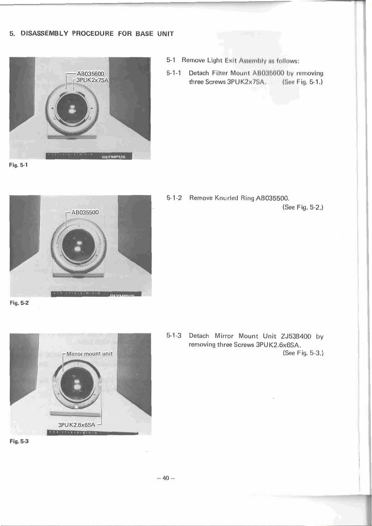
5.
DISASSEMBLY
PROCEDURE
FOR
BASE
UNIT
5-1
Remove
Light
Fxlt
Awrlr~il~ly
rirl
Ir~IInws:
Fig.
5-1
5-1
3PU
K2x
JSA
a
*
-
5-1-2
Detach
-1
threeScrews3PUK2xJt;A,
Remove
Filter
Mount
Knurled
Allfl:4tlf100
Ring
AB035500.
try
removing
(!;tloFig.5-1,)
(See
Fig.
5-2.)
Fig.
Fig.
5.2
5-3
rMirror
mount
unit
.
.
l"-l
--
Detach
removing
Mirror
three
Mount
Screws
Unit
ZJ538400
3PUK2.6x6SA.
(See
Fig.
by
5-3.1
Page 44

Fig.
5-4
5-1-4
Disassemble
a)
Remove
using
Adjustable
b)
Remove
the
Lens
Lens
Light
Exit
Unit:
Retainer
Spanner
ZA077700.
AB035800
OT0022.
(See
Fig.
by
5-4.)
7~-
Fig.
5-5
?Id diaphr
agm
"
1
unit
*
11,
1'1
I
1
'
5-2
Disassemble
5-2-1
By
removing
detach
Detach
Screw
Detach
Screws
the
the
Field
Circular
3PU
K2.6x5SA.
Plate
3PU
K2.6x5SAm
Field
Diaphragm
two
Screws
Diaphragm
Rack
A8025600
AB046500
Unit
as
CUK2.6x6SA,
from
the
(See
by
(See
by
removing
(See
follows:
Base.
Fig.
5-5.)
removing
Fig,
5-6.)
four
Fig.
5-6.)
KNw2*6$ 3PUK
2.0X
Fig.
5-6
5S
Remove
Remove
'-?4ABm,,
Rotary
Diaphragm
Frame
AB025500.
Blades
ZA078800.
[See
[See
Fig.
Fig.
5-6.)
5-6.)
Page 45

6.
ASSEMBLY
Fig.
6-1
PROCEDURE
Base
Arm
FOR
BASE
UNIT
6-1
Assamble
thr'
Anri
wlth
thn
Onse
Unit,
NOTES:
1.
The
Arm
should
not
to dcgrarle
Screws
2.
Arm
6-2
Assemble
6-2-1
6-2-2
cordance
Assemble
Diaphragm
Assemble
j
must
will
not
the
with
the
Diaphragm
Frame
Rotary
tion.
t1e
mor
flpp0rlrimt:e.
bc
t~ql~tr?~\rtl
camp
loose,
Field
Diaphmgm
proceclurr!
Blocl~ts
AB025400.
Frame
rnlsd
precisely
/See
Cirrnly
so
Unit
(rivan
helowr
ZA07R80Q
(Sec
AB025500
(Sol!
Fig.
that
Fig.
in
Fig.
so
6-1
the
in
ac-
with
5-6.)
posi-
5-6,)
as
.)
Fig.
6-2
7-
Cross
hair
Image
should
within
of
KN0029
of
fieEd
be
contained
this
circle.
diaphragm
6-2-3
6-2-4
6-3
Mount
by
rarily.
6-3-1
Position
Screws
Plate
3PUK2.6x5SA.
NOTE:
Check
operation.
Assemble
tian
Bring
shown
by
the
using
down
the
Diaphragm
Circular
tightening
Ficld
twn
Microscope
in
Fin.
NOTE:
Recommended
other
and
a)
b)
C)
d)
packing
deslc
surface.
Insert
the
of
Looking
scope
portion
Centering
illuminator
Microscope
through
KN0029,
(helicoid)
hairs.
Insert
down
Slide
back
KN0029
the
the
and
Field Diaphragm
AB046500
Rack
Screw
Diapl~raqm
Scr~ws
CUK3.6x6SA,
6-2.
to
apply
material
Adapter
insenion
Base.
Special
rotate
to
into
Field
Diaphragm
front
forth
lens
until
is
brought
by
tightening
(Soa
Blades
far
A6025600
3PUK2.6x5SAm
(SRF!
Unit
ante
Stand
on
soft
cloth
between
its
Nosepiece
B2KCf
port
at
Centering
its
front
focus
on
B2KCl003
all
the
portion
the
of
image
into
four
Fig.
5-6.)
normal
in
pasi-
Fig.
5-6.)
the
Base
tempo-
front
or
same
003
into
the
back
Tele-
lens
the
crass
and
stop
way
KNOD29
of
focus.
as
the
Page 46

E
-
e)
Loosen
Unit
the image
correctly
cross
STANDARD:
f)
Tighten
-
-
-
64
Assemble
given
below:
two
Screws
slightly and
of
centered
hairs
of
KN0029.
two
Screws
the
Light
of
Field
Diaphragm
move
the Field Diaphragm
Within
scale
of
it
leterally
concentric
1.5
divisions
K
N0029.
with
CUK2.6x6SA.
Exit
Unit
in
the
procedure
until
on
is
the
the
Fig.
6-3
6-4-1
Assemble
Unit
6-4-2
Clamp
OT0022.
6-5
Mount
three
the
Screws
NOTE:
It
is
recommended
ment
in
6-5
Assemble Knurled
Lens
ZA077700
23538400,
the
Lens
Light Exit Unit on
3PU
K2.6x6SA.
to
this
condition.
Ring
Retainer
perform
AB035500
in
Mirror
(See
Fig.
AB035800
(See
Fig.
the
Base
by
(See
Fig.
overall
(refer
in
position,
{See
Fig.
Mount
602.)
with
6-3.)
using
6-4.)
adjust-
to
9-3
1
6-5.)
Fig.
Fig.
64
6-5
6-6
Assemble
with
6-6-1
66-2
L---
Check
ing
If
engagement
and
Filter
Screw
the
range
the
graduations
teeth
Mount
AB03560D
3PUK2x7SA.
Field
Diaphragm
and
graduations.
are
between
of
Circular
Rotary
Rack
in
position
(See
Fig.
Unit
for
its
rniscalibrated,
Ring
A8035500
AB025600.
6-5.)
work-
adjust
Page 47

7.
DISASSEMBLY
PROCEDURE
FOR
BH2-CH
Fig.
7-1
Disassemble
I-?
manner:
7-1 - 1
7-1-2
the
Remove
Stopper
by
Remove
Detach
Stopper
H
lowering
the
Knob
K2.6x4SA
the
Condenser
ACUT.Gx4SA.
Stage
Mount
H
K2.6x4SA.
Condenser
Holder
A8059800
in
can
Mo'lder.
by
the
following
he
uncovered
(See
Fig.
by
loweriny
removing
(See
Fig.
7-1
.)
it.
Screw
7-2.)
I
I
I
Fig.
Fig.
7-2
7-3
-4
Remove
7-1
0077,
-5
Remove
Remove
Washer
7-1
7-1-6
/
Nut
AA007700
Tension
Ball
Screw
B3J32,
AA272600.
by
using
AB026900.
Pinion
AB026800
Tool
KKAA-
(See Fig.
(See
Fig.
7-3.)
7-3.)
and
Page 48

AA061400
7-2
Disassemble
ing
7-2-1
7-2-2
the
procedures:
Remove
Condenser
059600.
Remove two
Condenser
Centering
Holder
Clamping
Knobs
AB026000.
in
the
Knob
follow-
AB-
AB059600
Fig.
7-4
1
I
7-2-3
7-2-4
Detach
six
Screws
Remove
three
Plates
3PU
Condenser Mount
AB06'1400
K2x4SA.
by
removing
(See
Fig.
AB059000.
(See
Fig.
7-4.)
7-5.)
'Fig.
7-5
7-2-5
Dismount
Screws
Two
Rack
CU
K2.6x6SA.
Washers
NW2.9-450BN
the
Rack.
AB026700
SW2.6SA
are
removed
by
and
removing
(See
Fig.
two
Washers
together
two
7-6.)
with
Page 49

%
7-2-6
*
7-2-7
Remove
Remove
Screw
Spring
AA253000.
AA097400.
Fig.
7-7
8.
ASSEMBLY
PROCEDURE
FOR
BH2-CH
7-2-8
7-2-9
8-1
RemoveShaftAB026200.
NOTE:
The
Spring
Screw
CAUTION
Do
not
and
Shaft
AA253000
:
remove
Height
is
removed.
12WO.
After
or
xyloi
drv
Assemble
procedure
gasoline
cloth.
After
Shaft
or
AB026300
disassembly,
to
rernovt!
gasoline
the
Condnnsnr
below:
appl
yinq
cornplotcly
G
In
Wash
rcnse
pasi
can
ba
rlismotr
Adjustment
tlir:
parts
qreasc?.
Hnlder
Thcn,
with
Unit
OT2008,
tian.
(See
nted
Pin
(Scc
with
a
as
(See
Fig.
7-7.)
after
NP5x
Fig.
7-7.)
xylol
wipe
off
piece
of
per
the
assemble
Fig.
8-1
.)
Fig.
8-1
8-1
-5
8-1-6
8.1-7
8-1
-8
After
Spring
ilpplyinrl
AB076300
Tighten
After
surface,
applyirlq
059500
Attach
six
Aftcr
OT2006
Knoh
Aftet
OT7006
Knob
Check
ing
thrc!e
Scrcws
applying a small
AB026000
applying
AR059600
operation
Knob.
Grcasr:
in
Scr~w
AA3530OO
Grease
assemble
in
position.
Plates
3PUK3x4SA.
to
the
thread,
in
a
to
the
thread,
in
by
OT2008,
position.
{See
in
position.
(See
OT2008
Condenser
A6061400
Mount
(See
by
(See
amount
assemble Centering
position.
small
position.
manipulating
(See
amount
assemble
(See
assemble
Fig.
Fig,
to
the
Fig.
tightening
Fig.
of
Grease
Fig.
of
Grease
Clamping
Fig.
the
Center-
8-1
.)
8-1.)
slide
AB-
7-5.)
7-4.)
7-4.)
7-4,)
8-1-9
Assemble
tightening
Rack
two
AB026700
Screws
CU
K2.6x6SA.
in
position
{See
Fig.
by
7-6.)
Page 50

AB
026400
8-2
8-2-1
Assemble
With
Washers
Balls
83/32
assemble
NOT€
Apply
by
arrows.
the
Stage
it in
Grease
Mount Unit
AA272600,
placed
Stage
OT2008
on
Mount
to
as
follows:
NW4.6-26580
Pinion
Unit
the
AB026800,
AB026400.
parts
indicated
(See
Fig.
and
8-2.)
Fig.
8-2
/-
AA
s
y-'
272800
NW
4.6-3858n
8-2-2
8-3.3
!I-2-4
8.2-5
Asscrnbic?
tion.
Assernl>lr!
Tool
Assemhl~
this
tit~le
Screws
Check
Nut
K
KAA0077,
purpose,
lormarl
ACU3x4SA
Pinion
required.
a)
When
has
thrust
Loosen
Tighten
Tighten
b)
When
the
Loosen
Loosen
Tighten
Tcr~sion
Scr~w
AA007700
I(nat~
AB059800
fit
the
in
the
firmly.
for
its
the Pinion
play:
AA007700.
4
A8026900.
4
AA007700.
Pinion
rotates
AA007700.
-1
ABQ26900.
5.
AA007700.
A0026900
in
pas1
in
Pinion
Knob
operation and adjust
rotates
Shaft
and
too
too
in
tion
by
position.
into
tighten
(See
Fig.
lightly
heavily:
posi-
using
For
the
two
8-2.)
it
if
or
Page 51

8-3 Assemble Stage Moi~nl UtliZ with Condenser
Holder Unit as follows:
8-3-1
8-3-2 Check Condensctt Iloldt~t IJ~iil for its verti-
CU
K2.6x6SA
/
To be selected from among
AB059900 through AB060000.
Fig.
8-3
9.
OVERALL ASSEMBLY AND ADJUSTMENT OF BHS-F
Assemble
Condenser
Stagc
Mount
Holder Utlil
I111il
AB026400
Af31326500.
(See Fig. 7-1
cal motion and adjr1l;l
li
t
t?clrlir
c?d.
a) When the rack llils 11loy:
Place Wasll(,t
s
A130!1l)flO0 AB060000
under Ihc Hnclt, (Scc Fig. 8-3.)
b) When Waclt
Remove
or replacc!
c:tc?;rl.af;
Wusllrvs
tlrc!tri
wllli
(11
rllovtjs
A1113!~8%(3(3
IIiilltit?~ ones.
loo
heavily:
-
AB060000
(See Fig.
with
.)
8-3.)
STANDARD:
1
division on the
scale
9-1 Check
system
9-1-1 Place
scope
B21<C0002:
82KC10013: Cc!lituritiy adapter
K NO029
and
ulbtic~rl crli!lntrlcnl of illumination
lhc lollow~r~cj
Slarid
as
:
J~!js
oti 1Jie Micro-
sllc~w~r
i~r
Fig.
I'it\llc)l~'
9
1:.
lube
Sl)c.?cial cenlering telescope
Page 52

Pin hole image slioi~l(l
be contained
this circle.
within
9-1-2
9-1-3
9-1-4
Bring down Microscope Stand on
shown in Fig. 9-1. Recommended to apply
soft cloth or some other packing material
between Nosepiece and desk surface.
Looking through Special Centering Telescope
KN0029, rotate
to focus on the cross hairs.
Slide the front lens portion of
and forth to
I<C0002.
STANDARD: 1 division of cross hairs of
;I)
I1 tile S1-ANDAR D is not met (deviation
c?xct:eds 1 tlivisiotis), adjust position of
1I1(2 Ligllt Exit Utiil.
I,)
Alie~ loosening Screws 3PUK2.6x6SA on
Mirror
pillhole Image within 1 division on the
cross hair of
Tighten Screws 3PUK2.6x6SA.
its
front lens portion (helicoid)
focus on the Pin Hole of B2-
I<N0029.
Mourlt Unit ZJ538400, adjust the
KN0029.
its
front
as
KN0029 back
Fig.
9-1
B-KN0003
LB
Specimen
objective
--
Condenser
Cross hair of
*
WHKIOX
f
l
w
rn
I
I
KNOI)?Y
9-2 Assemble the Electrical Base with Microscope
Stand by tightening three Srews
9-3 Check and adjustment of Fine Adjustment
sensitivity
9-3-1 Use the following jigs on the Microscope
Standard as shown in Fig. 9-2:
B-KN0003:
LB40x objective
WHKIOX or
Condenser
Ordinary specimen
Fine adjustment sensitivity
STANDARD: Within
NOTE:
If no B-KN0003
observation tube instead.
Standard jig for tube length
WKlOx
visions on knob scale)
AB6x25SA.
4p (within 2 di-
is
available use any
Fig.
9-2
-49-
Page 53

9-3-2 Checki~~!l
a)
111
81 in:! tl~c
s~)ccir~~l:tl,
ttic Fill(: A(JJ~~!,IIII(*II~ l<1lol3.
b) Turri
Zl,ct
divisiol'ls)
retirrn
focus
it
an
read indication
Adjustmet11 I<tiol). 1 l~a? ciiffer(:nce of the
readings
be within
c) Check fine acij~~sftrl(!rit ~c:tlsitivity by
turning the
to those selected
occrdrrro
i~rslr\i~nc!~~l
rI(:iici
ili(i~(:~jf
I
in(:
Atlj~rstrno~ll 1<1iob 20p (10
ill
oilllihr tiit
tr~llil
111~
tlio
spncirrii?~i.
o~i ill(?
oblailiecl ill slc(3s
2
divisio~ls.
Itno11
io11
ill~31~t~~~~('tit is
iri
tlio
ill
slol)s
in focus on the
on
the scale of
(:(:I
ion, and then
brought in
111
this condition,
sc:alc?
of the Fine
ii)
i~tid b) must
cfilt?ctio~is reverse
;I)
;11,c1
b)
above.
A
Point
Block B2KC0009
Point B Stage
B2KCOOlO
Block
Point C Stage
Fig.
9-3
Stage
Specimen
1
Specimen
9-3-3 Check fine adjustment sensitivity
steps a),
b) and
c)
above
at
thrce points A,
and C specified in Fig. 9-3. (At poi~lls B and
C,
a
block
is
placed between the spccinlcri and
stage to change height of stage.)
UAR
D
is
9-3-4
9-3
5
If the STAN
UniL
of Gear
thc STAN DAR W cannot be rnet by adjust-
If
ing
Gear Unit ZJ856500, proceed
a)
Cliccl< the Gear and Shaft for engagement
arid
ZJ856500.
play in the Coarse Adjustment Knob.
trot Irrc?l, change setting
b) Cl~eclt the Ball Guide assembly
ings of
tlie
Wires and Rollers as well as
operation.
by repeating
B
(Sce Fig. 9-3)
(Sce Fig. 4-28)
as
follows:
(See 4-2-9)
for
sett-
its
Page 54

OPTICAL PATH DIAGRAMS
OF
BH2-BI AND BH2-TR
BH2-BI
BH2-TR
designates the combination of
designates the combination of
B2-BI
B2-BI
unit and
unit and
B2-BIC
B2-TRC
unit
unit
Page 55

10.
DISASSEMBLY
PROCEDURE
FOR BH2-&I
10-1
Disassemble
B2-BI
Unit
BH2-BI
as
per
the
procrdum
into
R2-81C
given
Unit
below:
and
Fig.
-
10-1
10-1-1
. .
.
-
10-1-2
Detach
three
Diopter
Screws
Disassemble
Finger
Rest
R
PUK2xlOSA
two
Screws
rest).
CUK7.llixSSA
Ring
AR033700
ACU2.Gx4SA.
Finqnr
Ali037700
{frorn
Rnst
L
by removing
nnch
(from
by
removing
(See
Fig.
AB032100
finger rest)
each
(See
Fig.
10-1)
and
Screw
and
finger
10-2)
Fig.
Fig.
10-2
10-3
10-1-3
Detach Graduated
ing
four
Screws
PUKZx4SA.
PFateAB031900
(See
by
rernov-
Fig.
10-3)
Page 56

Fig.
10-4
10-1-4
10-2
Disassemble
Disassemble
by
removing
B2-BIC
'B2-BI
four
Unit
from B2-BIC Unit
Screws CUK3x6SA.
Unit
as
follows:
(See
Fig.
10-4)
Fig.
-
10-5
---
-
- - - - - - - -
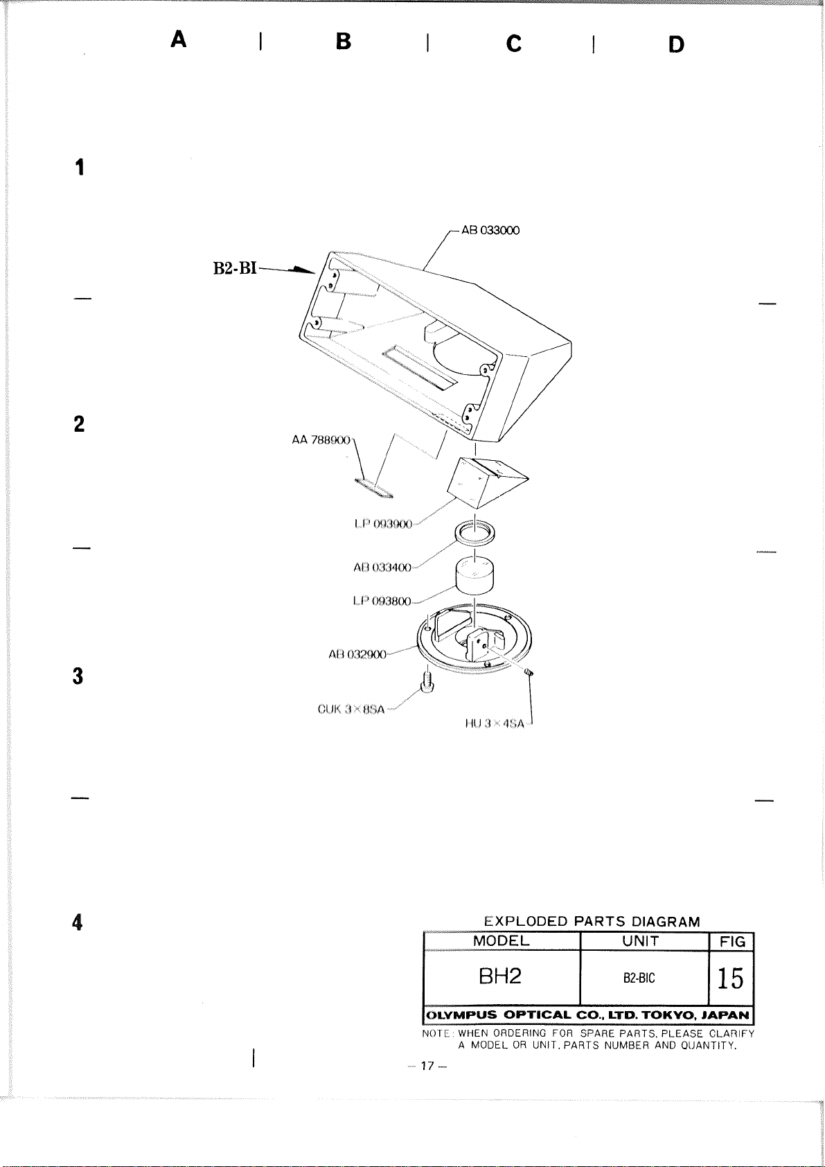
CP093900
1
10-2-1
-
-.
---
--
-
-,
10-2-2
Disassemble
Body
AB033000
CUK3x8SA.
Remove
P2
Prism
Mount
by
LP093900
AB032900
removing
from
three
(See
Prism
Screws
Fig.
Mount
from
10-5)
AB032900:
a)
After
remove
loosening
the
Adhesive
two
Screws
OT1028
(See
HU3x4SA,
(Araldite).
Fig.
10-6)
Fig.
106
Page 57

--
.I
---
-
10-3
Disassemble
B2-BI
Unit
as
follows:
Fig.
1
30-7
10-3-1
10-3-2
Remove
tube
length
a)
Remove
b)
Remove
AB031800,
Remove
Spring
device:
Spring
Spring
two
Keys
AB031200
Hanger
from
AB032800.
AB031200from
AB031800.
the
(See
(See
constant
each
Fig.
10-7)
Fig.
10-8)
Key
Fig.
I
I
Fig.
10-8
10-9
H
K3x5SA
/
10-3-3
Rernovn
a)
Prism
crrn
Screws
Do
b)
mount.
Prisms
ho
not
P3
Mount
and
disassembled by
H
K3x5SA.
remove
and
Prisms
Prism
P4:
R3,
removing
(See
P3,
P4
P4
23538700
Fig.
from
two
10-9)
Prism
Page 58

7---
Fig.
10-1
-
-
'-
0
10-3-4
Dismount
AB031100
5SA.
a)
Now,
Dovetail
by
removing two
Prisms
P5
(left)
and
and
P6
Dovetail
Screws
(See
Fig.
can
be
(right)
CUK2x
10-10)
disas-
sembled.
PS
(ZJ856700,Z3538800)
P6
(ZS856600,ZJ53$900)
(See
Fig.
10-1
1)
Fig.
Fig.
f
0-1
10-72
1
I
ZJ538800
10-3-5
Remove
side
Screws
10-3-6
Remove
side
Screws
I
Prism
Dovetail
H
K3x 1 OSA.
Prism
Dovetail
H
K3x 1 OSA.
Mount
ZJ538800
ZJ856700
Mount
ZJ538900
ZJ856600
by
removing
(See
by
removing
(See
from
Fig.
from
Fig.
right
two
10-1
2)
left
two
70-12)
Page 59

10-3-7
10-3-8
Detach
ride
Dovetail
by
placing
the
notch
with
a
tweezers
Extract
Circular
ZJ856700.
small
and
or
Inner
Tube
Cover
then
AB030700
amount
forcibly
a
similar
AB032600.
It
of
tool.
can
from
be
dislodged
solvent
extracting
(See
Fig.
right
through
it
10-13)
10-3-9
Remove
Sleeve
AB032600
a)
Remove
b)
Remove
in
Fig,
R
A8032300
as
follows:
Screw
Adhesive
t
0-1
3.
NU2x3SB.
by
heating
from
Inner
it
as
Tube
shown
Fig.
10-13
Page 60
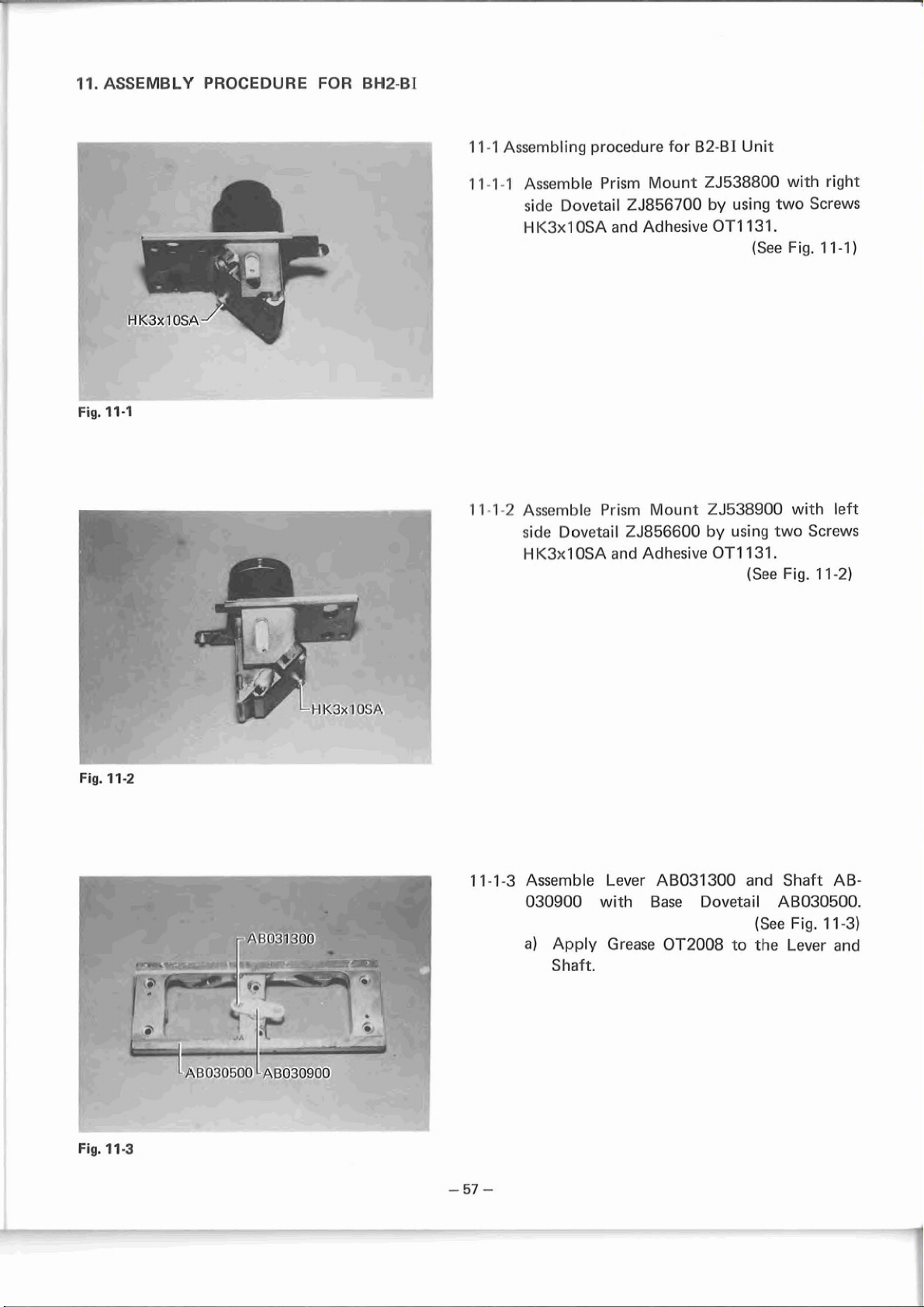
11.
ASSEMBLY
PROCEDURE FOR
-
-
<
- - -
.
BM2-BI
11-1
Assembling
procedure
for
82-BI
Unit
Fig.
11-1
Il-1-1
t8-
11-1-2AssernblePrismM~lountZJ538900with
Assemble
side
Dovetail
1-I
K3x1
OSA
side
Dovetail
H
K3xl
OSA
Prism
ZJ856700
and
Adhesive
ZJ856600
and
Adhesive
Mount
ZJ538800
by
using
OT113 1.
(See
by
using
OT1131.
(See
with
two
Fig.
two
Fig.
right
Screws
1
1-11
left
Screws
1
1-21
Fig.
P
Fig.
11-2
11-3
--
fi1r031300
11-1-3
I
1
I
Assemble
030900
a)
Apply
Shaft.
Lever
with
Grease
AB031300
Base
Dovetai
OT2008
to
and
I
(See
the
Shaft
AB-
AB030500.
Fig.
11-3)
Lever
and
Page 61

r---
Fig.
11-4
-
-
-
.
.
-
-
- - -
1
T
1-7-4
Assemble
tion
respectively.
Apply
a)
surfaces
left
and
Grease
of
the
right
side
OT2008
Dovetai
Dovetails
(See
to
Is.
Fig.
the
in
posi-
11-41
sliding
Fig.
11-5
11-1-5
1 1-1
-6
11-1-7
Assemble
two
Move
two
Screws
the
two
operntion.
Temporarily
P3
and
P4
5SA.
Douctnils
CUK2.Gx5SA
dovetails
clamp
Z,!538700
and
the
with
AB031100
for
each.
(See
Fig.
check
far
Prism
two
assembly
Screws
(See
by
using
1
smooth
HK3x
Fig.
1-51
of
17-61
Fig.
1
1-6
Page 62

Fig.
11-7
-
-
-
.
.
--
-.
-.
11-1-8
1
1-1
-9
1
1-1
-1
Assemble
position.
Check
play or
diameter
0
Assr?mblc
Key
AB047500
movement
of
friction. Select
keys
to
achieve
Spring
or
keys
in
smaller
smooth
AB031200
AB033800
(See
Fig.
their
slots for
or
larger
operation.
(See
Fig.
in
position.
(See
Fig.
in
3
1-7)
T
1-7)
11-8)
Fig.
--
Fig.
1
1-8
-
11-9
- - -
-
-
--
11-1-1
I
Hold
the Spring
Hangers
AB0328000.
(See
Fig.
11-9)
Page 63

r.1
11-2 Optical alignment of B2-BI unit
Jigs
11-2-1
Use the following
the Microscope
StantJ.
B2KC0402: Ji!j
i111~1
lor
111
ism alignment
KN0014: Conl(:~ ill!] ol~jective (200mm)
C-1
:
10x c.ycl)ioce with cross hair
B2-BI unit on
(See Fig. 11-10)
Fig. 11-10
11-2-2
Adjust
posilion
taking Prism ,~ssc:~r~ljly ol
standard.
1 1-2-3
If B2-Bl unit
fit
ti11 foil I~ulwt~c~~~
Prism MOUIII.
11-3 Assembl~~i(~
11-3-1
Assen~l~lc I9
111
or;cvfrrtt* lot 132 BIC Unit
Mounl A130:3>~/300
Aftcr i11sc:t Iirlrj
mal<c
!;1lrc3
colrlljlc!lr!ly, 1 l1111r
wil
li
Acilic?s~vr:
01
I:OI~IIOI
I~III
1'1
1'1
I*,III 1'1 illlo
111,11
111
(:(4~1i~?~i1
0
I
107t3.
IJ~~srll
Mount ZJ538700
P5
and P6
IN:
c:i?~>te~ed properly,
flit-
Ii1islrl assembly and
l..P093800 with Prism
Ifle
Prism Mount,
14111
has
bcen inserted
it
at
three points
as
Fig. 11-1 1
Fig. 11-12
LP093800
1
1
3
2
Asc;c:lnl)l($
fS1
:
I31e!;\
celrir!lll
OT
1
0313.
~~lit~~~lt~t~jt~l
tl~~~l)lrla(g~l>
11
at
A13033400 with Prism
evenly against prism PI and
three points with Adhesive
(See Fig. 11-1 1)
1 1-3-3 Assor~~l~lo 17rism P2 LP093900 with Prism
Moitrrl AU032900:
Align
til,
of
Prism P2 with that of Prism PI
nrrtl Illc~i cement them to each other. After
rnalcing sure that no gaps remain between
Prism
P2
and diaphragm and that
it
has been
fittcd s~i~lgly into the groove, cement the
at
diaphragm
OT1028.
Tighten two Screws
two points with Adhesive
(See Fig. 1 1-1 2)
HU3x4SA.
Page 64

Fig.
Fig.
11-13
11-14
B2-B
I
'~~0005
Align the scrcw having
circular
adjusting liolo.
mark wi1.h
I
Center
cross
l~ait
11-3-4 Center Prism Mount AB032900:
a)
Assemble the following Jigs and B2-BIC,
B2-BI units
as
shown in Fig. 1 1-1 3:
B2KC1403: Alignment Jig
KN0005: Centering objective
C-1
:
1 Ox eyepiece with cross hair
(See Fig. 1 1-1 3)
11
3
5
Assemble procedure for BH2-BI
a)
Assemble B2-BI Unit to B2-B IC Unit with
four Screws
CUK3x6SA.
NOTE:
1-licsc
two Units should be aligned flush
witti each other at their adjoining edges.
I)) Wl1011 Alijlllment Jig B2KC1403
to
1311%B1, three adjusting holes in
1371<C:1403
slio~~ld
be aligned with three
S1:1uws (:IJI<:3x13SA in Prism Mount
AL30329(10
c)
lr~se~l
into the right eyepiece sleeve.
C-l
d)
By using the adjusting holes of the align-
of
l3H2
I31.
Eyepiece 10X with Cross Hairs
ment jig, adjust position of the Prism
Mount
AB032900 until the cross hair of
C-1 intersects with the center of the
center cross hair.
(See Fig. 11-13 and Fig. 11-14)
e) If centration
is
impossible by adjusting
position of the Prism Mount, check Prism
its
P2 for
assembly. (See Fig. 11-1 1)
f) If P2 has no defect, adjust mounting
positions of both B2-BI Unit and B2-BIC
Unit.
g)
Insert C-1 into left Eyepiece sleeve, and
check that the deviation of the left
is
eyepiece axis
within two divisions, if
any, from the right eyepiece axis.
is
attached
1 1-4-1 Assemble Graduated Plate
using four Screws
11-4-2 Assemble Finger
Finger
Rest
PUK2x4SA.
Rest
L
R
AB032200 by using Screw
PUK2xlOSA and two Screws CUK2.6x5SA
11-4-3
for each Finger
Temporarily Clamp Diopter Ring
Rest.
by using three Screws ACU2.6x4SA.
AB031900 by
(See Fig. 10-3)
AB032100 with
(See Fig. 10-2)
AB032700
(See Fig. 10-1)
Page 65

KN0022
11-5 Adjustment of mechanical tube length
Stage
Condenser
11-5-1
Adjust mechanical tube length of the right
side eyepiece sleeve
a)
Use the following Jigs and BH2-BI Unit on
the Microscope Stand:
B2KC0406: lnterpupillary distance jig
KN0007:
Standard objective
KN0022: Special WFlOx
C-15: Focusing magnifier
(See Fig. 11-1 5)
b) Set scale of KN0022
at
0,
or red line.
(See Fig. 1 1-22)
c) Looking throu!lh thc C-15, move the front
lens portion
1,000 mm away
ill
or oi~l until an object
froin the C-15 is brought
into focus. (See Fig. 11-16)
Fig. 11-15
Fig. 11 -1
d)
Bring
tlit!
sl~c?cilirt:n of KN0007 into
focus l)y atijirsting longitudinal position
of
Slunve AU032300.
e)
WIIII rlie specimen in focus fix Sleeve
A136132300 and Inner Tube AB032600.
(1)
Bond with Adhesive OT1027
6
utle point.
(3)Uotld with Adhesive OT1028
at
at
Il~tee points. (See Fig. 11-17)
f)
Assemble.
Circular Cover AB030700 in
~~osition.
Uo~id with Adhesive OT1028
ot
I
hree points.
at
two
(See Fig. 11-17)
Fig. 11-17
-
Page 66

1 1-5-2
Adjust left side tube length:
a)
After focusing on the right side, put KN0022 and C-15 into the left side sleeve.
b) Taking tube length on the right side
as
standard, turn Diopter Ring AB032700 in
either direction to bring the specimen into
focus.
c) Loosen Set screw ACU2.6x4SA on Diopter
AB032700. Turn the Diopter Ring
Ring
only until the index of the Finger Rest
L
indicates 0 on the Diopter Ring. Then fix
tlie Diopter Ring by tightening Set screw
ACU2.6x4SA.
Fig.
11 -1
1
1
I)rvi,~tio~l
6
I
0111
:;
/c(:t
#I)
lC,3I
1
AN
IV~!)
11:;~
ol
parcentration for right and left
,lACS
I)AIj
I1
(i~~i;i(je fortnation plane of ob-
:
0.2
ill(! follow~~~g
Jigs
on 1 tic Microscope
Sland:
Cotilcririg ol~jcctivc: KN0005
1 Ox eyepiccc with cross hair: C-1
1))
Place C-1 in the right and left eyepiece
sleeve and make sure that the cross hair
of
C-1 is within 3 divisions of the center
cross hair of
KN0005.
(See Fig. 11 -1
8)
c) If this STANDARD is not met, repeat the
adjustment in step 1 1-2 above.
d) When the right and left optical axes are
3
within
KN0005, take the one nearer the center
of
8
cross hair as standard and adjust the other
within 2 divisions on
divisions of the center cross hair
KN0005.
Page 67

Left optical axis
Fig.
11-19
Center cross hair
-
.-
-
Right optical axis
Center cross hair
/
""-
e) When the right and left optical axes are
compared with each other in Fig. 11-19,
for example, the right optical axis
the center cross hair on
case, the left optical
be adjusted within 2 divisions of the right
optical axis on thescale of KN0005 (within
the black enclosure).
The left optical axis should (1)
matched with the right optical axis or (2)
be within 2 divisions
corner inside the black enclosure. Position
of the left optical axis within 2 divisions
at
the lower right corner of the black
enclosure
the specification is met. Adjust the left
optical axis
hair on
described above, if possible.
f) If the right and left optical axes cannot be
adjusted within
cross hair on
adjustment
is
the least desirable, although
as
close to the center cross
KN0005 in condition (1) or (2)
2
divisions of the center
thc scale of KN0005, repeat
iri
slep 1 1
KN0005. In this
;xis must therefore
(See Fig. 11 -19)
at
the upper left
-2
above.
is
nearer
edeally be
11-6-2
lmage
distance
Image for
0.1
a)
b)
c)
d)
shift Ily atJjustlnent of interpupillary
tnstiot)
Placr?
the
Stand:
Ccr~ tering ohjc!ctive: K N 0005
1
Ox
~;yepicce with cross Iiair: C-1
Put
C
1 into the right side eyepiece sleeve.
Wit11 the interpupillary distance set
tnirii~num, check the 10x eyepiece for
Irscijlion of
I<NCl005. Then, increase interpupillary
disaa~lce to maximum and read shift of
the
cross hair image (on the scale of
KNBO05).
SPAN DAR D: Within 1 division
Put
C-1 into the left eyepiece sleeve and
cticcl< image of the cross hair in the
indentical manner.
If the STANDARD
adjustment in step 11-3 above. (Especially
take care not to leave gap between the
Prism and Prism Mount.)
plar~o
of objective: Within
followi~lg Jigs on the Microscope
its
cross hair on the scale of
is
not met, repeat
at
the
Page 68

Fig. 11 -20
Exit pupil
Within 20%
pubul diametot
(within 7 (jivi~io~ls)
of
exit
11-6-3 Eccentricity of exit pupil of objective
(within 20%)
a)
Put Special Eyepiece KN0029 into the
right Eyepiece Sleeve and place the Objec-
tive
lox in the optical path. Check the
exit
pupil of the objective for
its
eccec-
tricity from the cross hair on KN0029.
It must be within 2 divisions on KN0029.
(See Fig. 11-20)
b)
Put KN0029 into the left side Eyepiece
Sleeve and check eccentricity in the
illclontical manner.
1:)
I f ctxcccntricity exceeds 2 divisions, repeat
:rtJjrrslrnenL
in step 11-2 above.
NOTE:
IW,tko
strto
~iot, to leave gap between the
I?
I\ll\
h~Ol111~.
Fig. 11-21
Red line
Field lens portion
Screw
1
division: 2
Front lens portions
mm
w
Graduated platc
~in~er' res~
One division: 0.1
KN0022
ABI):3
1
13
A13032200
!I00
tnlri
11
(5
4
11 -6-5
I%osil~orl
101
itrtcll~upillary distance of 62mm
(62 4 1ti\11>)
a)
By using
position of Finger Rest
tlie
Graduated Plate. The reading must be
62
i
b)
If the STANDARD
positions of Finger
Graduated Plate
Imm.
Jig
B21<C0406, read left side
R
AB032200 on
(See Fig. 11 -21)
is
not met, adjust
Rest
R
AB032200 and
AB031900.
Adjustable range of interpupillary distance
(at
least 55mm - 75mm)
a)
The Finger Rests R and L must not be
brought into contact with each other
when the interpupillary distance
is
Set
minimum separation.
b) Light must not leak from between the
Graduated Plate and Finger Rest
interpupillary distance
set
at
R
with
maximum.
Check of tube length
a)
Jigs to be used:
Special WF
lox: KN0022
Standard objective: KN0007
b) Attach KN0007 to the revolving nosepiece
and rotate the scale on
KN0022 of the
0,
or Red line position. (See Fig. 11 -22)
Insert
Sleeve. If image
pupellary distance
KN0022 into the right side eyepiece
is
blurred while inter-
is
increased from the
minimum to the maximum, turn the
Front lens portion of
the scale in
KN0007 into focus.
KN0022 to bring
at
Fig. 11 -22
Page 69

STANDARD: Within 0.5 division (on
scale of
KN0022)
c) If the above STANDARD is
not met, repeat adjustment
as
per step 1 1-5 above.
11-6-7
Difference in portrusion between right and
left eyepiece sleeves
STANDARD:
Witliin 1 mm
a) Jigs to be used:
Special
WFlOx: I<N0022
Standard objecl ive: I<N0007
Focusing magnifier: (2-15
b) Set the scale of /<NO022
line position
side
Eyepiclce Sl~?evc. Adjustment of
C-15, refer
and itiserl
lo
1 1-5 1 c)
at
0,
it
into the right
.
or Red
c) Place C--15 ovct KN0022 and
check
of
through
d) If the spor;i~nc:~i
properly,
KN0023
to
KN0007
C
to
sco
it
1lii:
specimen
is
(21
ope1 ly focused
15.
of
I(N0007
tlrlrl
rhr? front lens portion of
IN
111g
ilie specimen into focus.
is
not focused
e) lnserl 1<1\10022 ;ltid C--15 into the leftside
eyepit?cct slcov~;.
f)
If
tl~:
IOCIIS(:C~,
Oriricj
!I)
Allr!t
P;I)(V:IIII(~II
ILIII\
il
iiilo
t
v~iiovi~icl [lie eyepiece, measure
of
1<NU007
Oio))t(?r
lo~;\is.
is
not properly
Ring AB032700 to
ilist,~rlcc:s fro171 Fi~iger Rest L AB032100
i~tid
1:
illget+
Resl
R
AB032200 respectively
lo
ilrr:
sl~cve
Ll!llr~tu~i~e
ti}:,
(by using slide calipers).
it1
the measured distances must
I)(: will~i~i Imm between the right and left
siclcs.
11)
11
tlie
STANDARD
;111ji!st1nc11t
in
step 11-2 above and check
is
not met, repeat
oticc: again. (See Fig. 11-23)
AB032100
Fig.
11
-23
Page 70

12.
DISASSEMBLY
Fig.
'12-1
PROCEDURE
"-
-
FOR
BH2-TR
12-1
Disassemble
BI
unit,
For
disassembly
BH2-TR
into
procedure, refer
B2-TRC
unit
to
and
T
0-1
B2-
-1
to
10-1-4.
17
1
1
Detncl~
Screws
--
--
-
I
12-2
25SA.
Disassemble
Cover
AB033200
AB4x45SA
B2-TRC
and
unit
as
by
two
per
removing
Screws
(See
Fig.
the
following
two
AB4x
32-2)
procedures:
Fig.
b
12-2
I
I
A8/1x25!
AB3x8SA
I
--
r-7
--,
I
I
d
7
1
I
1
2-2-1
1
2-2-2
Remove
The
Shaft
small
amount
with
a
unscrew
Dismount
four
Screws
light
path
is
rubber
it.
Dovetail
AB3x8SA.
Selector
screwed
of
Adhesive.
sheet
AB033500
Shaft
in
and
fixed
Grasp
or
similar material
by
(See
A8034300.
with
the
Shaft
and
removing
F
iq.
12-31
a
Fig.
12-3
Page 71

GUK
2.6 X 8SA
A
x6sAAB
3X8sA
12-2-3 Remove Click Stop Assembly by removing
Screw AA063200. Spring AA063100 and Ball
B1/8 are removed together with the Screw.
(See Fig. 12-4)
Fig. 12-4
AB 033500
063100
AB031500
12-2-4 Remove Stopper AB4x6SA.
(See Fig. 1 2-4)
12-2-5 Remove Prism Mount AB033300.
(See Fig. 12-4)
12-2-6 Detach P8
LP094600 from Prism Mount
AB033300 by removing Screw HU3x4SA.
(See Fig. 12-4)
12-2-7 Detach Prism ZA071000 from Prism Mount
AB033300 by removing two Screws H U3x
4SA. (See Fig. 12-4)
Fig. 12-5
12-2-8 Detacli Ci~ccrl;rt I)ovt:lail AB034200 from
Body
A13U31d
100
IJ~ relnoving three Screw
C111<3xOSA. (See Fig. 12-5)
1%
3
Disassc:tril)lc
13
3
1
For
132
131.
Utiil.
tli:;;~ssernl)ly ~~rocedure, refer to 10-3
Page 72

13.
ASSEMBLY PROCEDURE
Fig.
Adhesive
13-1
OT1028
FOR
BH2-TR
Circular doveLaiI
I
AHU,-14i1:'l)[~
13-1 Assembly procedure for B2-BI unit
For assembly procedure for B2-BI unit, refer
to 11.1.
For optical alignment procedure, refer to 11-2.
13
3
Asso~nbly procedure for B2-TRC Unit
13
2
1
Assumble
A11034200 by applying Adhesive
Ilituc!
PI
poirlls.
LP093800 into Circular Dovetail
OT1028
(See Fig. 13-1)
I:!
:(
2
/\*i*,~*ttil)l~i CSi,$l~lllagm AB033400 in position
I,y Irl)ljly~licl Aciliesivc OT1028
at
three points.
(See Fig. 13-1
NO
I
I-31
1
Ill
<IIIII
llita III,J~~I~I,I~IT~ stio~~ld be in flat
l:ol~l<l~;l.
I
lrca
Adtiesivc! sllot~lcl
ylar:ilry
PI
and
tlic
Ile
applied after
Uiapliragm in position
repoctivoly.
3.
Cement prisrn and diaphragm together
with 3 dabs of adhesive.
at
)
2
3
13
Temporarily assemlbe Circular Dovetail unit
on Body
K3x8SA.
CU
AB033100 with three Screws
13-2-4 Assemble light path selector unit in position
in the procedures'given below:
a)
Assemble Dovetail AA221400 with Dove-
AB033500 by tightening two Screws
tail
H
K2.6x8SA.
b) Assemble Prism Mount AB033300 with
Dovetail
AB033500 (apply Grease OT-
2008). (See Fig. 1 3-2)
c) Assemble Stopper AB4x6SA with Dove-
tail
AB033500.
d) Assemble Plate AB031500 with Prism
Mount
Screws PU
e)
Assemble Click Mount ABO40100 with
Dovetail
Screws CU
AB033300 by tightening four
K2x4SA.
AB033500 by tightening two
K2.6x8SA.
f) Assemble Ball B118, Spring AA063100
and Screw AA063200 to Click Mount
AB040100.
Fig.
13-2
NOTES:
Apply Grease OT2008 to the Ball before
it
-
inserting
69
-
in postion.
Page 73

Fig.
Prism
33-3
fixing
block
-
-
'd
-
2KC0404
Lock
screw
g)
Adjust
screw
h)
After
Dovetail
B2KC0404,
two
l
nsert
i)
AB033300,
Clamp
pus11
and
tiqhtan
Tiqlitnn
i)
thr!
PrEsrn
Remove
k)
Jig
ancl
OTT
Adh~sivr
Assernl)lr!
1)
ing:
(1)
Droo
Mnurit.
(2)
Apply
ti0
t
jirrnir~q tirllltcned
Sh~llrlc.
(3)
Aqsr3rril)l~
tinil
(4)
(5)
Assemble
Rotly
operation
AA063200
placing Prism
AB033500
clamp
knobs
078
located
Prism
ZA07100Q
located
thc!
Prism
the
two
Mount,
thv
apply
nr
tour
wnq
Prim
Prisrn
After
on
Screws
Prism
n
npplicrl
Atlt~r.;ivr!
of
Scrrws
iqhrtnn
n~rnovn
ftjrrr Scrcws
Aasemhlt!
Ilw
OT
will1
screws.
.Ilq
1
Ilotly
Knob
ARO34300
Shaft
(apply
of
the
click
in
or
out.
Mount
on
them
by
on
the Jig.
into
turning
the
Jig
to
info
the
lock
screw
HU3x4SA
Mount
srnnll
amount
points
LP094600
(same
before
LP094600
Agent
HU3x4SA
t32KC0404.
condition,
131
to
each Screw.
thv
light
A0933100
AR3x8SA.
AB034400
(apply
Adhesive
A8034300
Adhesive
by
moving
AB033300
Positioning Jig
tightening
Prism
the
the
prism
Prism
on
the
located
unit
of
place where
disassembly
as
per
into
OT1131
After
path
(See
and
the
Mount
Prism
side,
Mount
Jig.
on
from
the
Adhesive
fallow-
the
Prism
to
the
and
then
con-
apply
selector
by
using
Fig,
1
3-41
with
Shaft
1.
OT1126).
with
the
0T1126).
Fig.
'1134
-
-
-
--
Page 74

P-
Condnnsnr
13-3
Center
Assemble
TRC
the
Units
Standard
1
Ox
NOTE:
Assemble
Unit,
prism
in
the
following
on
the
objective:
eyepiece
refer
to
the
following
Jigs,
Microscope
with
cross
B2-BI
1
1-3-5
Unit
a).
procedures:
and
B2-BI,
Stand.
KNOU05
hair:
C-1
(See
with
B2-
Fig.
13-51
B2-TRC
Fig.
Fig.
13-5
13-6
.
13-3-1
,
4
13-3-2
13-3-3
13-3-4
13-3-5
Insert
C-1
Adjust
C-1
is
KN
0005.
Check
shows
Cover
AA581100.
When
Prism
optical
ZA071000
034200
lnsert
check
axis
right
that:
is
eyepiece
to
sight
position
centered
Shaft
too
for
C-1
within
AB034300
much
alignment
their
into
the
two
axis.
side
Eyepiece
of
Dovetail
with
the
friction,
and
Circular Dovetail
positions.
left
Eyepiece
deviation
divisions,
sleeve.
ABO33500
center
is
of
cross
(See
movement.
adjust
impossible,
the
left
if
any,
until
hair
Fig.
1
3-61
If
position
check
AB-
sleeve,
eyepiece
from
on
it
of
and
the
Page 75

AB3x40SA
13-4 Adjust tube length B2-BI Unit
For the procedure to adjust tube length, refer to
11-5.
13-5
Asseml~le the Phototube Unit in the procedure
given below:
13-5-1
13-5-2 Assemble
Asserii1)le Wasllc?rs (lo
AB033800 It~rorr$jh AR034100) and Mount
ABO336C30 with Cover AB033200 by using
Scrcws AB3xrlOSA.
three
by
usillq two Si;~c!wt; AU4x45SA and two
Screws
III(?
I'llotot~rl)c Unit with the body
AU4x2!sSA.
be
selected from among
(See Fig. 13-7)
Fig.
1
13-8
(:"I
5
"
Biological specimen
'I
I
--
72
Ill-($
Oplicill ;~li!jrrlnoll. ant1 19~rfocalil.y alignment for
Plwt ot~rl,c Ullil
13-6-1 Parivcalil y alignment
a)
I"lirco ~lic following Jigs on the Microscope
SLitt~(l
as
shown in Fig. 13-8:
B?l<(:0406: lnterpupillary distance jig
I<NOO22: Special W F I Ox
C
15: Focusing magnifier
Oiological specimen
1-U40x objective
1))
Carry out steps b) and c) of 11-5-1 (given
lot- BI-12-BI)
Bring the specimen into focus by turning
c)
Lhc Fine Adjustment Knob.
d)
Place KN0022 and C-15 into the
Pliototube.
Move the front lens portion of KN0022
e)
until the specimen
and read indication on the scale.
-
is
brought into focus
Page 76

LBI
OX
ol)jc~c:~
IVI'
13
6
f) If deviation exceeds 1 division on the
scale of
from among
KN0022, adjust Washers (selected
AB033800 through AB-
034100) for proper focusing.
STANDARD:
0.1 mm on the phototube side taking the
rig171 side of
I
1
division on the scale of KN0022).
2
O~)li~:~~l aIiqnt~ic?~it
I'ltac:(x BIi2TR and the following Jigs on
,I)
i1111
MICI oscol,c Stand
$1
:
fll
as
STANDARD (Within
as
shown in Fig. 13-
li21<(;0/10(i: I~~lt:tpcry,illary distance jig
II~I<(;IO~~~: Aliryir~~(:t~t jig
l<N0(104
3t1W I I It
LB
:
I
1
Ox:
I
I
Oxol)jc!cl ivc?.
l)l:~ti?
oc:~~sillcj c?ycl)it?cc
(Sce
Fig. 13-9)
Fig. 13-10
,35WHK
Bi
side
b)
Clamp B2KC1408 on Phototube AB033600 with mark
matched with mark
"0"
on the latter
"o"
on the former.
(See Fig. 13-1
Rotate the front lens portion of Alignment
Jig
B2KC1408 until the image of the
is
cross hairs
Insert 35WH KlOx into the right side Eye-
C)
piece Sleeve of
brought into focus.
BI unit. Shift KN0004 on
the stage until the center cross hair of
KN0004
hair of
is
aligned with the double cross
35WHI<lOx.
(See Fig. 13-1 1)
0)
Fig. 13-1 1
Page 77

Fig. 13-12
STANDRAD: 0.1 5 divisior
(on the
scale
1
s
?
of I<N0004)
KN0004
d) Correct point centration and image
rotation of B2KC1408 on the Phototube
side by adjusting position of Phototube
AB033600.
MOTES:
1. The center should be adjusted within
1.5 divisions on the scale of
KN0004.
(See Fig. 13-1 2)
Fig. 13-13
Image rotation
,,
Within 1 division
on the scale of
$
KN0004
2. Image
within 1 division on the scale of
KN0004. (See Fig. 13-1 3)
13-7 Overall Checks
13-7-1 Checks on
Refer to
13-7-2 Checks
on
a) Ecctrii~ ic:~ry
W ill~ili
tile I iclljl
Ralc:~
I
a~iorl).
11)
Irnaqca totalloll wtlh tcyard to the right
s~cfti
(,illow,~t)lc totalic)~~).
c)
I',rl
ltscalily
WI~I~III 10.1m1m laking the right side of BI
Irlllt
,is
I<c*l~:r
rotation should be corrected
I31 sitltr.
I
1
ti
<livc:li
TOI
131
13-UI unit.
IYlrotr~i~ll,c?
0.
I!,
$!tic.
10
1-1cj.
of
n
l
sirlo
OII
11~:
of
ul
1
:3
trt~il
I'liotol~~lse side taking
~lliir as standard.
13
(;~ilowable decent-
I4crCer to Fig. 13-1 3
standard.
to
Fig. 13-7.
NCJ7
E:
I-o!
rctatljt~stment procedures of the indi-
vidcl,~l ircms, reference should be made to
13
1
ltiroi~gh 13-6 (assembly procedures).
Page 78

14.
DISASSEMBLY
PROCEDURE
FOR
BH2-SV
14-1
nimssnrnhlr!
tht!
tlie
~TOCM~CI~I!
givan
Vertical
below:
Control
Knob
Unit
in
Fig.
--
14-1
.
AB021800
--
-
14-
1-1
14-1
-2
Rornavr!
two
Screws
the
Knob
Remove
Washer
Knot)
counterclackwisc?.
Spring
AB02
ARQ21800
ACU2,Cx
AB021700
1600.
10SA
by
and
then turning
(See
Fig.
and
(See
Fig.
loosening
14-1)
Plastic
14-2)
Fig.
Fig.
'14-2
'14-3
14-1-3
Loosen
two
A8021400
clockwise.
Screws
and
then
ACU2.6x5SA
rcrnovr!
it
by
(See
on
turning
Fig.
Knob
14-3)
Page 79

I-
Fig.
14-4
--
-
-
-
-
14-1-4
14-1
-5
Loosen
021500
counterclockwise.
Removr!
Screw
and
Plastic
ACU2.6x5SA
then
remove
Washer
on Nut
nut
by
(See
AB02
turning
Fig.
1600
AB-
14-4)
and
Spring AR071700.
(See
Fig.
14-5)
1;;
Fig.
14-5
5
4-1
14-1
-7
-8
Dismount
021
100.
Dt?tiicl~
inq
t
ti
rnrj
Rcmowt?
Knot,
Vertical
Screws
Plastic
AR021400
Rack
AB020000
C
U
K3x6SA.
Washer
AB021200.
and
(See
(See
Pinion
Fig.
by
remov-
Fig.
AB-
14-5)
74-61
Fig.
148
Page 80

Fig.
14-7
14-1-9
9
,-
K
KAA6rlSU
-
14-1-10
Dismount
two
nnrnavr!
fi4!;R.
Vernier Scale
Screws
Nl~t
H
K2-414SA.
NN4SA
Mount
Ily
using
by
(See F I
Tool
(See
Fig.
removing
g.
14-7
)
KKAA-
14-8)
Fig.
Fig.
14-8
14-9
Dismount
removing
Remove
Mount
AB020700.
Knob
two
Screws
Pinion
Mount
AB020700
AB3x8SA.
(See
ABOT0900
Fig.
from
by
14-9
Knob
1
Page 81

Fig.
14-10
-1
14-1-13
DetachLateral
ing
NO
Screws
CUK3x8SA.
RackAB01930Obyremov-
(See
Fig.14-12))
L
Fig.
14-11
--
D2
--
Kr:o!dj!~
-
.<
-
I
14-2
Disassemble
in
14-2-1
14-2-2
14-2-3
the
following
Set
the
else,
good
scratching
shown
in
NOTE:
No
particular
description,
Support
photo
Looscn
for
three
Dismount
removing
the
Lower
Stage
proccdures:
Stage
to
the
Fig.
against
support
Stage
14-1
I.
Jiq
is
surface,
implied
nlthough a special
Frnmn
your
R7KC0505,
mfcrcncc.
adjusting
Vertical Guide
three
Screws
AB3x8SA.
and
a
box
the
Screws
Lateral
or
something
Stage
in
in
a
manner
the
following
withbut
Jig,
is
used
only
(See
Fig.
H
U3xGSA.
(See
Fig
A6019200
(See
Fig.
Guide
as
called
in
14-1
1)
14-12)
by
14-12)
Fig.
14-12
Page 82

14-2-4
Remove
and
four
eight
Wire
Balls
Guide
B3,
Casing
AB019100.
(See
A6018800
Fig
14-13)
Fig.
14-13
j
-2r.675
-
11
Dismount
Rcrnovr:
nnrl
four
I
7
J~SITFIILIII~
7
III~
two
Scrrws
Lower
eight
Wire
Clill
Stage
ABOl8500.
Balls
B3,
Guides
HoIr10r
ABOl9100.
ARO19400
AR3x8SA.
(See
Casing
(See
Fig.
14-13]
A601
l~y
rernov-
Fig.
14-14)
8800
Fig.
14-14
AB018700
Fig.
14-15
,.
--
,
n
14-2.9
I
14-2-&
Set
up
Fig.
14-1
Dismount
removing
the
5.
four
Stage
Lateral
Screws
in
a
manner
Guide
AB3xGSM.
as
shown
(See
Fig.
14-15)
AB018700
(See
Fig.
14-15)
in
by
Page 83

I
-
-
-
14-2-10
!
I
fig.
14-16
Remove
Feed
Plate
01
8900
eight
Balls
ABOl8600,
and
four
Wire
B3,
Casing
four
Guides
AB018800,
Wire
Guides
AB019000.
AB-
Page 84

15.
ASSEMBLY
PROCEDURE
FOR
BH2-SV
15-1
Assembly
of
Lateral Ball
Guide
Unit
Fig.
r-
15-1
-
15-1-1
15-1
-
--?--
15.1
-2
3
Set
up
Fig.
15-1.
Mount
Mounl
the
Stage
two
Wire
Cnsinq
in
a
manner
Guides
ABOl88OO
A601
and
as
(See
8900.
(See
eight
shown
Fig.
15-1)
Fig.
15-13
Balls
in
B3
Fig.
Fig.
15-2
15-3
15-1-4
15-1
-5
1
5-1
-6
15-1
-7
Place
two
Plate
A601
Mount
Mount
Mount
applied
Wire
8600
two
Wire
Casing
eight Balls
with
AB018800.
Grease
Guides
and
mount
Guides
I33
which
Of
ABOT9000
them.
(See
AB019000.
are preliminarily
2008.
(See
on
Fig.
Fig,
Feed
15-3)
3
5-3)
Page 85

Fig.
154
Arm
15-1
P---
-
-
15-1-8
Arljustment
knob
Put
two
Guide
AW018700
porarily
-9
Pressing
with two
AB3x6SH. Check
Guide
according to
NOTES:
1.
The
feed
out
friction
2.
The
3.
The
casing
Wire
by
using
down
fingers,
Feed
Guides
and
four Screws
Lateral
the
Plate
must
or
play.
Plate
must
AB018900on
assemble
Lateral
them
AB3x6SH.
(See
Fig.
15-41
Guide
AB018700
retighten four Screws
movements
steps
in
move
must
be
centered
NOTE
of
Lateral
below:
smoothly
move
with
lightly.
the
with-
tern-
Wire
Guide.
b
Fig.
15-5
15-1-10
Apply Adhesive
points
Upper
a)
on
Lateral
Stage.
Apply Shellac
AB3xGSH
to
OT1028
Guide
OT1131
prevent
at
At3018700
to
them
three
(See
four
from
(See
or
four
and
Fig.
75-51
Screws
loosening.
Fig.
75-51
Page 86

15-2
Assembly
of
Vertical
Ball
Guide
unit
Fig.
158
15-2-1
1
5-7-2
15-7-3
17
Set
in
Fig.
Tcmperarily
61
91100.
Mount
I'l1icnCnsinr~ABOl8800a.t:thecenterofWire
Gi~hIo
1;
7.7
Altytly
rirollrlt
Aftnsh
Stnqcl
Place
Guide
1
15.7
15
up
the
'Upper
15-6.
assemble
Wire
Guide
A~1CI19100,
Ilrrnar!
tlrttrn
ARO?
Casing
OT2008
in
Wir~
Gi~idr! AR019100 to
8500
AB018800
ABOT9100.
Stage
AB019100.
to
position.
i~nd
clamp.
Clip
a.t
Unit
(See
eight
(See
the
center
as
shewn
Holder
Fig.
Balls
B3
Lower
Fig.
of
AB-
t
5-6)
and
15-71
Wire
Fig.
15-7
15-3-8
15-2-9
Apply
mount
Place
Guide
temporarily.
Grease
them
Wire
A5019200
OT2008
on
the
Guide
to
eight
Casing.
AB019100
and
assemble
BallsB3and
on
Vertical
them
(See
Fig.
75-81
Fig.
75-8
Page 87

Fig.
15-9
p
I
/HU3x6SA
15-2-10
While
by
turning
Vertical
NOTES:
The
without
15-2-1
1
Apply
points
Upper
15-2-1 2 Apply
HU3xGSA
them
operating
Screw
Guide
Lower
friction
Adhesive
on
Vertical
Stage.
Shellac
and
from
loosening.
the
Lower
HU3xGSA.
AB019200
Stage
and
must
play,
OT1028
Guide
OT
1
1
31
Screw
AB3x8SA
Stage,
Then,
firmly.
(See
move
at
three
AB019200
{See
to
adjusting
(See
adjust
clamp
Fig.
1
5-9)
smoothly,
or
four
and
Fig.
1
5-1
0)
Screw
to
prevent
Fig.15-101
it
Fig.
15-1
0
Page 88

Fig.
OT2008
15-1
1
15.3
15
3
Assemble
Il~r!
1
Asst!rnhle
:I)
I,)
the
following:
Apply
%ti
r
face.
Ansnmhln
Vertical
ttre
Knob
Grcnsrr
Wnshrlr
OT3008
AI~~~70~1~~.
c]
T~WT!~{~I
~brily
r!fiw~~bldfj
Control
Mr~rrnt:
An031
Nt~t
Knob
to
each
000
with
NN4SA.
(Sen
unit
Fig.
as
per
sliding
Pinion
15-1
1)
Fig.
15-12
15-3-2
15-3-3
15-3-4
Assemble
the
stage:
a)
Apply a small
I127
b)
Position
as
stage.
Temporarily
079300
to
the
to
be
by
NOTE:
The
Lateral
no
thrust
Finally
K
K6450.
NOTE:
The
with
play.
Tighten
l~t~r~l
no Pntornl plny.
Knob
Screws
the
Knob
parallel
assemble
using
Rack
Nut
rnck
Mount
amount
of
AB3x8SA
Mount
with
the
Lateral
two
Screws
must
operete
NN4SA
milst
opnrntfl
assembly
Adhesive
and
tighten
assembly
side
(See
Fig.
Rack
CUK3x8SA.
(See
Fig.
smooth
by
usinq Tool
smoothly
with
OT-
of
15-1
AB-
15-1
with
it.
so
the
2)
2)
Page 89

AB021200
1
5-3-5
Assemble
Washer
AB021200.
OT2008
*
+
15-3-6
AB021400
AB021'100
AB021700
AB021600
AB021800
AB021700
I
AB021800
15-3-7
15-3-8
15-3-9
15-3-10
15-3-1
15-3-1
15-3-13
15-3-14
15-3-15
Mount
Assemble
Mount
Mount
Assemble
using
Screw
1
Mount
2
Mount
Assemble
Screws
Temporarily
020000
Temporarily
0
19900.
NOTE:
Preliminarily
Washers
Knob
AB021400.
Pinion
Washer
Washer
Washer
Waslirtr
ACU?.Rxl
in
and
AB023
A8021
AB021600
Nut
A6021500
ACU2.6xSSA.
AR023
AR021700
Knnb
nnnmhlr!
position.
nssnmt)lc
apl~ly
Pirrion
100
700
in
in
600
in
in
Al3021800
OSA,
Vertical
Vertical
Grease
Shaft.
in
position.
position.
position.
in
position
position.
position.
by
using
(See
Fig.
Rack
Vernier
OT2008
by
two
15-13)
AB-
AB-
to
Fig.
Fig.
95-13
15-14
-0T1144
15-4
Overall
--
-
-
-
-
15-4-
1
adjustment
Adjustment
a)
Engage
Rack
AB019300.
NOTE:.
Adjust
assure
play
b)
Adjust
Place
When
(I
(2)
or
the
motion
1
Loosen
on
Turn
wise
IOSA.
position
smooth
unevenness
motion
Knob
of
Lateral
Pinion
of
stagk
on
is
two
AB021800.
Knob
and
tighten
Travel.
AB020900
of
the
Rack
motion
the
too
Setscrews
AB021800
without
the
entire range.
Rack:
the
Microscope
(See
heavy:
two
Screws
with
Lateral
st,
as
to
friction,
Stand.
Fig.
1
5-1
4)
ACU2.6xlOSA
countercIock-
ACU2.6x
Page 90

When
motion
(11
Adjust
clockwise.
is
by
too
light:
turning
Knob
ABQ21800
1
!h
4
7
M~nsuring moving
G
nuqr?
OT
1
144.
!:I'ANDARD:
I-)
Alittr
I
Adjustment
Adjust
similar
rr~otion
1111
I'ir~in~~
lrrr
*:rl~r~lth
',
I
AN!jAIIl>
Al
III~II
l~lrll
ll*ll
l\v
1
lit*
I
rhc-C
NIITF
11
1111%
1
Edllak
1
ryrru;lt
a;trhpt;
of
Vertical
to
that
once
motion.
I~~II~~I~
:I)
Vertical
for
50
has
again and
friction
14r
Irvr1
tlrrclr
~lir
0111111
Travel
adjusting
force
-
120
been
or
from
owit
oplvate
C)
Travel
in
with
(See
F
ig.
g
adjusted,
check
the
play
cannot
paly
or
'?rolling"'.
smoothly,
nhnve.
a
manner
lateral
{See
travel,
Fig.
Tension
1
5-1
4)
engage
Rack
be
quite
T
5-1
5)
L----
-
B2KC0503
..
-
Measure
moving
force
with
Tension
Gauge
OT1144.
STANDARD:
Moving
travel.
15-4-3
OT0317
Adjustment
a)
b)
L-
.
4~
c)
condition:
Place
the
Put
Specimen
H'L
on
Measure
holder
OT0317.
STANDARD:
the
and
of
stage
stage.
the
200-
Specimen
on
300g
Same
the
Holder
gap
between
stage
with
0.3
?
0.1
as
that
for
Holder
Microscope
BH2-HR
the
specimen
Thickness
(See
iFig.
mm
lateral
Stand.
or
BH2-
Gauge
15-3
6)
NOTE:
A
special
holder
are
stage
used
base
in
Fig.
and
standard specimen
1
5-1
6.
Page 91

Fig.
15-?7
d)
If
(
(2)
e)
Adjust
1319500
(1)
(2)
the
STANDARD
1
)
When
Adjust
-
AB0206)
and
stage.
If
gap
remove
to
meet
Specimen
gap
Adjust
01
9400.
If
the
detach
STAN
gap
is
by
is
narrower
Spacer.
the
between
and
Lateral
position
gap
cannot
lateral
DAR
is
net
met
wider
than
specified
inserting
between
STANDARD,
Holder
Spacer
Specimen Holder
(See
than
specified
If
it
is
still impossible
with
{See
Lateral
Vernier
(See
of
Clip
be
adjusted
set
it
once
0:
0.05
-
0.2rnm
(AB0204
Fig.
15-1
replace
a
new
Fig.
15-1
Scale
AB019600.
Fig.
15-18)
Holder
properly,
again.
7)
the
one.
7)
AB-
AB-
I
I
I
Fig.
Fig.
15-78
15-19
A0019900
AB019800
15-4-4
Adjust
019800
a)
Adjust
b)
If
the
cletacli
it
once
STANDAR
gap
between
and
Vertical
position
gap
Lateral
again.
of
cannot
Vernier
D:
0.05
Vertical
Vernier
Plate
AB085600.
be
adjusted
AB019900
-
0.2mm
Scale
AB019900.
[See
Fig.
15-19)
properly,
and
AB-
set
Page 92

f
6.
DISASSEMBLY
AND
ASSEMBLY
PROCEDURES
FOR
BH2-HR
Fig.
16-1
ZA
07
1600
PSK
,-
,I,
.-.
16-1 Dis~ss~mbl~ procedure (for
16
1
1
ll~rt~ove
1
t;
1
7
fl~rnovr
Ill,)
411
111
I:)
I
fi
7
A*ivt~o~~l~l
l(i
3
7
Assrvmhle
ZA07ltiOQ
two
Knobs
Clip
ZAO71600
Rrrnnvr?
I'libn~ovr
IiIM
I
!~~IIIIOV('
y
two
Spiral Spring
700
for
l'in
1
)I
OCP~~II~~
Spirnl
in
Screws
R
H
2.H
$10036700,
(fnr
S~~r~rirj
~~ositinr~
BH2-H
AB036500.
(ZA071500
PSK2x4SA.
AA569700
L)
AA036900,
R
I
12-H
R)
AA569700
l~y
\rsing
R)
(See
(See
two
Fig.
for
Fig.
and
Screws
16-1)
BH2-
(AA-
16-1)
Clip
PSK2x4SA.
1
ti
2 3 If
2
-
4';A
16
2-4
vertical
Holder
the
pins
Place
play
A0058300
AB036700
Knobs
AB036500
or
friction
and
-
is
causecl
Clip ZA671600,
A5036900 adequately.
in position.
hetween
select
Fig.
16-2
16-2-5
-I
Check
stage
a)
gap
and
Clamp
the
stage.
top
surface
071600
STANDARD:
b)
If
the
clip
for
with
a
NOTE:
A
stage
ment
between
Clip
ZA071600
Specimen
Measure
of
the
with
Thickness
0.2
STANDARD
adjustment
new
one.
designed
is
used
in
Fig.
the
top
as
follows:
Holder
-
exclusively
the
gap
stage
Gauge
0.4mm
is
not
or
replace
B2-HR
16-2.
surface
between
and
Clip
OT0337.
(See
Fig.
met,
for
of
(HL)
16-2)
bend
the
adjust-
the
on
the
ZA-
the
part
Page 93

17.
DESASSEMBLY
Fig.
17-1
PROCEDURE
FOR
BH2-AAC
17-1
Disassembly
11-1
-1
17-1
-2
Dismount:
removing
Remove
Diaphragm
of
Diaphragm
Circular
three
Screws
Unit
Dovetail
PUK2x6SA.
Ring
AB040700.
AB040800
by
Fig.
17-2
i
Page 94

17-2
Disassembly
of
Lens
Unit
Fig.
17-3
17-2.1
17-2.2
1
7
-7.3
I
7.24
17-3
5
1
1
7
R
Remove
justable
Remove
Remove
Rcrnove
H~lrnov~!
~cictillllrr
l7clrtir1vr
Retainer
Spanner
LensZA077900.
Spacer
Lens ZA078000.
Retainer
Spanner
Lans
NOTES:
1.
I-clr~s
ZA078100
rmlrm
3.
I-lrrir
7A07n
rri1111r~
Ill*
t:kku~~
AB040500
OT0022.
A
B040400.
Al3040300
OT0022.
EA078100.
i/
mrrllrsl
11u
100
is
AR040200
whc:n
rurnoving
should
rcl>I;lcetl
cemented
and
extreme
it.
by
by
(See
no1
with
to
using
Ad-
using
Ad-
Fig.
17-3)
be
removed
a
new
one,
Condenser
care
must
Page 95

18.
ASSEMBLY
PROCEDURE
FOR
B1-12-AAC
3
8-1
Assemble
Body
A6040200
Front
Lens
as
follows:
ZA078100
with
Condenser
(See
Fig.
I
18-71
Fig.
18-7
OT1028
-ZAO78100
18-1-1
18-1-2
18-2
Assemble
Tighten
Spanner
18-3
Put
18-4
Put
Apply
Adhesive
ZA078100
ABO4Q200.
a)
Apply
cumference
between
b)
Wipe
Place
let
it
dry
off
the
Condenser
for
the
Lens
Retairwr
OT0072.
Lens
ZAO780(10
Spoccr
All1140400
OT1028
and
put
Adhesiv~
since
the
Coridt!nsor
excessive
Body
24
hotlrq,
l,A4"s
100
Al304O5(10
Irr
(ru!;ltlon,
In
to
in
Condenser
to
the
it
scrvos
Body
Adhesive.
upside
iri
position,
IIV
using
~rnci
lion.
Front
entire
also
as
and
down
Adjustable
(See
Fig.
(Soc
Fig.
(See
Fig,
Lens
Body
cir-
sealing
Lens.
and
77-31
17-3)
17-3)
Fig.
18-2
18-5
Put
Lcns
18-6
Assemt)ln
usinfl
18-7
Ass~mlllrl r!irtlit.
position.
NOTE:
For
assernhly,
cage
Fig.
18-7,
ZAO77!SO0
Rr?t~~i~l~r
A~lj~~ti~t~l~
in
o
clockwise
Iri
~rnslt
Annrlfl5Ofl
Sllnr~rlrv
Diaphriiqm
the
Blades
sequence,
Ion.
t
1'1
nr)??.
Hlntl~s
should
ISco
Fig,
in
position
(Scc
Fig,
%A078700
be
placed
as
shown
T
7-3)
1
7-3)
in
by
in
the
in
I
I
I
Page 96

I
I
-
18-8
Assemble
tion.
Diaphragm
Ring
AB040700
in
posi-
NOTE:
When
diameter
the
should
Diaphragm
be
about
is
stopped
T
mm.
(See
dawn,
Fig.
its
18-31
Fig.
3
8-3
18-9
18-1
Assemble
using
0
Check
Circular
three
Screws
BH2-AAC
Dovetail
PUK2x6SA.
for
its
proper
AB040800
operation.
by
Page 97

19.
DISASSEMBLY AND ASSEMBLY PROCEDURE FOR BH2-CD
19-1 Disassembling procedure
Procedures for disassembly BH2-CD are quite
similar to those for disassembly BH2-AAC.
19-2 Assembling procedure
Procedures for
similar to those for
assembly BH2-CD are quite
asse~nl~ly BI-12-AAC.
.-
-At3
040800
..*.
94
Page 98

20.
CHECK SHEET FOR POWER SUPPLY B-BDS-2
NOTE:
For circuitry and connecliolr, rt?lc~
1. Check Standard
Check
Item
(1) Maximum output
(2) Minimum output
(3)
LED lighting voltage
2. Troubleshooting Flow Chart
Lamp does not light
10
1111.
Irlll~~:l~t*(l
3v
01
ItW*
Lei, (1s
b and
(II~~I~II~III- 1 I
t;
111
~lio
l1*11 11qIr1
I)',
dir(+(:t~o~~.
a: AlwL~yc3 lit (111I~lt)
b:
Lii
;31
4
5
[)
'fV
c: Lit
,3t
I~~II
11
*8iq~~~~a~~l
liglrti~rll YOII~IIII~
iil+,
tl~~rcjrtt~rrs,
C;lic?ck r3roc:otlrr~ca
Mcasurin(j 1)oittl: I ,llrll) socl<et,
II~I~SC!
Measurilv1
ccluplc typo class
Sarnc
$1,
Same
Voltages
be
i~nst~
ulrrcv\t:
0.t)
as
(
1 ) abovc.
as
(1 ) al~nvtr,
at
chcclc ~)oir~l:;
6,8, 10 and 12V.
i111tJ
~c~odition
TIic:r
lno
or I\icllier
for
C
sli;lIl
Remove SW107
and lneasirr
110i1nts
Ilrrncd
it
voIl;iqr* I~r*lwt~~*rt
sIrow11 l~~~low
ON).
ror base
(I)OWl
{WIIII
cr~lit
li
tiwllc*l~)
!jw~lt:l~
I
ort~ll/o cause and turn ON (push in) circ~~ir I)rc?al<ctr
l'
No
SW 102 defective (DS0105 for line power vr~l
I
wt) he order or I OOV or DSOl06 for 200V)
liitll:
on
Page 99

1
YES
I
r
Turn OFF SW102 ErSW103 and check ele- defective (DS0095 for line power voltage on
crtical continuity between the two the order of
points in the same procedures.
YES
FlOl (built in fuse) blown (DE0082 for line power
voltage on the order of
Primary wiring of TI 02 (main transformer) broken
(DT0123 for line power voltage on the order of 100V
or DT0124 for 200V)
.
100V or DS0096 for 200V)
100V or DF0083 for 200V)
Check connector pins for applied
voltages:
(1) AC 7V across pins No. 3 and
No. 5 on J301 (with mark
"J 1
")
of UY PC64?
(2) AC 100V or 1 15V (AC 220V
240V) across pins No. 1 and
or
No. 2 on J301 (with mark
"J 1
")
of UY PC56?
I
UYPC64 or UYPC65 defective
LEDs do not glow
Check connector pins for applied
voltages:
I
I
(1) When AC 7V
Secondary winding of TI07 I,tol<eti
(2) When AC 100 - 240V
Primary winding of
line power
DT0106 for 200V)
is
not al)plic?tl:
voltage
~111
is
l~ot i~l~lzlied:
-1
101
1111:
I,rolct?n (DT0105 for
0111cr
OC
100V or
(1) AC 30V across pins No. 6 and
8
No.
65?
(2) AC
across pins No. 9 and No. 10
on J201
on J201 (JI) or UYPC-
0
-
12V (lamp voltage)
(JI) or UYPC65?
I
t
UYPC65 defective
(1) When AC 30V
Secondary winding of TI02 I)~ollsc:n
(2) When AC
0
See
"Lamp
0
--/
Lamp cord wire broken
is
riot ill~~~lioci:
0
-
12V
is
does not liglit"
no1 al~l)litr(l:
i~l,o~t:.
Page 100

21.
ELECTRIC CIRCUIT DIAGRAM
CIRCUIT DIAGRAM
 Loading...